EP0010332A1 - Elément d'accouplement et méthode pour sa fabrication - Google Patents
Elément d'accouplement et méthode pour sa fabrication Download PDFInfo
- Publication number
- EP0010332A1 EP0010332A1 EP79200587A EP79200587A EP0010332A1 EP 0010332 A1 EP0010332 A1 EP 0010332A1 EP 79200587 A EP79200587 A EP 79200587A EP 79200587 A EP79200587 A EP 79200587A EP 0010332 A1 EP0010332 A1 EP 0010332A1
- Authority
- EP
- European Patent Office
- Prior art keywords
- cylinder
- coupling element
- lla
- parts
- cylinder parts
- Prior art date
- Legal status (The legal status is an assumption and is not a legal conclusion. Google has not performed a legal analysis and makes no representation as to the accuracy of the status listed.)
- Withdrawn
Links
- 230000008878 coupling Effects 0.000 title claims abstract description 16
- 238000010168 coupling process Methods 0.000 title claims abstract description 16
- 238000005859 coupling reaction Methods 0.000 title claims abstract description 16
- 238000004519 manufacturing process Methods 0.000 title description 4
- 238000000034 method Methods 0.000 claims description 4
- 238000007789 sealing Methods 0.000 claims description 4
- 239000012530 fluid Substances 0.000 description 2
- 150000001875 compounds Chemical class 0.000 description 1
- 238000005516 engineering process Methods 0.000 description 1
- 238000009434 installation Methods 0.000 description 1
Images
Classifications
-
- F—MECHANICAL ENGINEERING; LIGHTING; HEATING; WEAPONS; BLASTING
- F16—ENGINEERING ELEMENTS AND UNITS; GENERAL MEASURES FOR PRODUCING AND MAINTAINING EFFECTIVE FUNCTIONING OF MACHINES OR INSTALLATIONS; THERMAL INSULATION IN GENERAL
- F16L—PIPES; JOINTS OR FITTINGS FOR PIPES; SUPPORTS FOR PIPES, CABLES OR PROTECTIVE TUBING; MEANS FOR THERMAL INSULATION IN GENERAL
- F16L23/00—Flanged joints
- F16L23/02—Flanged joints the flanges being connected by members tensioned axially
- F16L23/024—Flanged joints the flanges being connected by members tensioned axially characterised by how the flanges are joined to, or form an extension of, the pipes
- F16L23/028—Flanged joints the flanges being connected by members tensioned axially characterised by how the flanges are joined to, or form an extension of, the pipes the flanges being held against a shoulder
- F16L23/0286—Flanged joints the flanges being connected by members tensioned axially characterised by how the flanges are joined to, or form an extension of, the pipes the flanges being held against a shoulder the shoulder not being formed from the pipe
-
- F—MECHANICAL ENGINEERING; LIGHTING; HEATING; WEAPONS; BLASTING
- F16—ENGINEERING ELEMENTS AND UNITS; GENERAL MEASURES FOR PRODUCING AND MAINTAINING EFFECTIVE FUNCTIONING OF MACHINES OR INSTALLATIONS; THERMAL INSULATION IN GENERAL
- F16J—PISTONS; CYLINDERS; SEALINGS
- F16J10/00—Engine or like cylinders; Features of hollow, e.g. cylindrical, bodies in general
- F16J10/02—Cylinders designed to receive moving pistons or plungers
-
- F—MECHANICAL ENGINEERING; LIGHTING; HEATING; WEAPONS; BLASTING
- F16—ENGINEERING ELEMENTS AND UNITS; GENERAL MEASURES FOR PRODUCING AND MAINTAINING EFFECTIVE FUNCTIONING OF MACHINES OR INSTALLATIONS; THERMAL INSULATION IN GENERAL
- F16L—PIPES; JOINTS OR FITTINGS FOR PIPES; SUPPORTS FOR PIPES, CABLES OR PROTECTIVE TUBING; MEANS FOR THERMAL INSULATION IN GENERAL
- F16L23/00—Flanged joints
- F16L23/16—Flanged joints characterised by the sealing means
Definitions
- the invention relates to a coupling element for connecting ylinder too from Z, in particular for a hydraulic cylinder tube of an elevator, and a method for producing the compound.
- the invention has for its object to provide a coupling element through which individual cylinder parts can be connected to one another to form a cylinder unit of unlimited length without the seals of the piston movable in the cylinder unit being quickly damaged.
- this object is achieved in that the cylinder parts to be connected to one another each have at their ends a concentric twist to the cylinder bore, that the cylinder bore is coaxial centering bushing which fixes to one another is placed on the twists of the cylinder parts which are butted one against the other, and that both cylinder parts are drawn together by connecting elements.
- the cylinder parts with their inner diameters are mounted exactly concentrically to one another and it has been found that the damage to the seals of the piston is substantially reduced. It was found that the reason for the above-mentioned prejudice of the experts against the composition of the hydraulic cylinder from several cylinder parts essentially rests in the fact that it had not yet been recognized that the rapid damage to the piston seals was not caused by the joint between the cylinder parts themselves, but is due to the lack of accuracy of concentric assembly of the cylinder parts.
- the hydraulic cylinders can be successfully assembled from individual cylinder parts, since the coaxial mounting of the cylinder parts is now ensured.
- a sealing ring can be provided between the centering bush and the concentric seal of each cylinder part.
- the cylinder parts are preferably pulled together via pressure rings with associated flanges, which are pulled together via the connecting elements, as characterized in claims 3, 4 and 5.
- the damage to the piston seal can be further reduced if, according to claim 6, the bores of the pipe sections are rounded at the ends to be connected.
- the feature of claim 7 ensures that when a cylinder part is replaced, the centering bush is pushed completely onto the adjacent cylinder part.
- each cylinder part is centered on a cone and is turned concentrically on its outside, in that the turned cylinder parts are fixed coaxially by means of a centering bushing and then pulled together.
- the cylinder sleeve can first be placed on the twist off of one cylinder part so that one end of the centering sleeve projects beyond the end of this cylinder part and then the second cylinder part with its twist can be inserted into the centering sleeve and pushed against the first cylinder part.
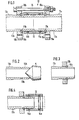
- the coupling element is generally designated 10.
- a centering bushing 13 encompasses the abutment point of the two butt-fitting cylinder parts 11a and 11b and fixes the cylinder bores coaxially to one another.
- Sealing rings 14a and 14b are the zen in circumferential grooves Trierbuchse 13 arranged and prevent leakage of the hydraulic fluid between the twists 12a, 12b of the cylinder parts 11a, 11b and the inside of the centering bushing 13.
- connecting elements 15 are provided which, in the exemplary embodiment shown, consist of several screws with nuts consist.
- pressure rings 16a, 16b are inserted in grooves 17a, 17b, which are provided on the twists 12a, 12b.
- Flanges 18a, 18b are located on the sides of the pressure rings 16a and 16b facing away from the free ends of the cylinder parts 11a, 11b.
- the flanges 18a, 18b have a plurality of bores 19a, 19b distributed in the circumferential direction and aligned with one another, into which the screws are inserted.
- connection elements can also be used, such as a screw connection with a union nut, or the like.
- one end of a cylinder part for example IIIb, is centered on a cone K and the outside of this cylinder part is turned concentrically to its inside diameter over a length which corresponds at least to the length of the centering bushing (13) (FIG. 2).
- the groove 17b for the pressure ring 16b can be pierced at the same time.
- the end of the other cylinder part 11a is then centered and machined on the cone K in the same way.
- a flange 18a, 18b is then pushed onto each cylinder part 11a, 11b, and a pressure ring 16a, 16b is inserted into each groove 17a, 17b, as shown in FIG.
- the centering bushing 13 with the sealing rings 14a and 14b is pushed onto one end of a cylinder part, for example 11b, so that one end of this bushing projects beyond the end of this cylinder part.
- a nschliessend is the end of the other cylinder part lla, illustrated by dashed lines in Figure 4, inserted into the centering bushing 13 and pushed against that of the first cylinder part (llb).
- the two cylinder parts are now mounted with their inner diameters exactly coaxially to each other and the connection can be completed by inserting the screws and tightening the nuts, whereby the flanges 18a, 18b lie against the pressure rings 16a and 16b and accordingly contract the cylinder parts 11a, 11b .
Landscapes
- Engineering & Computer Science (AREA)
- General Engineering & Computer Science (AREA)
- Mechanical Engineering (AREA)
- Chemical & Material Sciences (AREA)
- Combustion & Propulsion (AREA)
- Actuator (AREA)
- Types And Forms Of Lifts (AREA)
- Pistons, Piston Rings, And Cylinders (AREA)
Applications Claiming Priority (2)
| Application Number | Priority Date | Filing Date | Title |
|---|---|---|---|
| LU80415 | 1978-10-25 | ||
| LU80415A LU80415A1 (de) | 1978-10-25 | 1978-10-25 | Kupplungselement sowie verfahren zur herstellung desselben |
Publications (1)
| Publication Number | Publication Date |
|---|---|
| EP0010332A1 true EP0010332A1 (fr) | 1980-04-30 |
Family
ID=19729026
Family Applications (1)
| Application Number | Title | Priority Date | Filing Date |
|---|---|---|---|
| EP79200587A Withdrawn EP0010332A1 (fr) | 1978-10-25 | 1979-10-15 | Elément d'accouplement et méthode pour sa fabrication |
Country Status (4)
| Country | Link |
|---|---|
| EP (1) | EP0010332A1 (fr) |
| AU (1) | AU5206279A (fr) |
| LU (1) | LU80415A1 (fr) |
| NZ (1) | NZ191891A (fr) |
Cited By (5)
| Publication number | Priority date | Publication date | Assignee | Title |
|---|---|---|---|---|
| CN102094866A (zh) * | 2009-12-14 | 2011-06-15 | 安东石油技术(集团)有限公司 | 一种连接稳固的液力缸 |
| CN102094871A (zh) * | 2009-12-14 | 2011-06-15 | 安东石油技术(集团)有限公司 | 液力缸的新型连接体 |
| WO2011141026A1 (fr) * | 2010-05-12 | 2011-11-17 | Man Diesel & Turbo, Filial Af Man Diesel & Turbo Se, Tyskland | Structure d'étanchéité d'extrémité de tuyau |
| CN105822860A (zh) * | 2016-05-09 | 2016-08-03 | 武汉理工大学 | 用于激波管的非焊接式法兰结构 |
| CN115493006A (zh) * | 2022-11-22 | 2022-12-20 | 中国空气动力研究与发展中心超高速空气动力研究所 | 利用管道法兰实现快速对心夹紧和拆卸的管道装置及方法 |
Citations (8)
| Publication number | Priority date | Publication date | Assignee | Title |
|---|---|---|---|---|
| DE318640C (fr) * | ||||
| US2081021A (en) * | 1936-04-24 | 1937-05-18 | Bernard F Smith | Pipe coupling |
| AT278454B (de) * | 1966-05-24 | 1970-02-10 | Mannesmann Ag | Losflanschverbindung für Druckrohrleitungen |
| DE2050544A1 (de) * | 1970-10-15 | 1972-04-20 | Dapra Geb Berghem A | Glattrohrverschraubung für Höchstdrucke |
| DE2104860A1 (de) * | 1971-02-02 | 1972-08-10 | Mead Corp | Dichtende Rohrverbindung |
| US3861724A (en) * | 1972-03-09 | 1975-01-21 | Georg Spinner | Device for the rotary axially fixed connection of two concentric components |
| US3937501A (en) * | 1973-05-26 | 1976-02-10 | Karl Weinhold | Pipe coupling |
| DE2453672A1 (de) * | 1974-11-13 | 1976-05-20 | Vebe Kvarnmaskiner Ab | Kupplung fuer insbesondere rohre |
-
1978
- 1978-10-25 LU LU80415A patent/LU80415A1/de unknown
-
1979
- 1979-10-15 EP EP79200587A patent/EP0010332A1/fr not_active Withdrawn
- 1979-10-19 NZ NZ19189179A patent/NZ191891A/xx unknown
- 1979-10-23 AU AU52062/79A patent/AU5206279A/en not_active Abandoned
Patent Citations (8)
| Publication number | Priority date | Publication date | Assignee | Title |
|---|---|---|---|---|
| DE318640C (fr) * | ||||
| US2081021A (en) * | 1936-04-24 | 1937-05-18 | Bernard F Smith | Pipe coupling |
| AT278454B (de) * | 1966-05-24 | 1970-02-10 | Mannesmann Ag | Losflanschverbindung für Druckrohrleitungen |
| DE2050544A1 (de) * | 1970-10-15 | 1972-04-20 | Dapra Geb Berghem A | Glattrohrverschraubung für Höchstdrucke |
| DE2104860A1 (de) * | 1971-02-02 | 1972-08-10 | Mead Corp | Dichtende Rohrverbindung |
| US3861724A (en) * | 1972-03-09 | 1975-01-21 | Georg Spinner | Device for the rotary axially fixed connection of two concentric components |
| US3937501A (en) * | 1973-05-26 | 1976-02-10 | Karl Weinhold | Pipe coupling |
| DE2453672A1 (de) * | 1974-11-13 | 1976-05-20 | Vebe Kvarnmaskiner Ab | Kupplung fuer insbesondere rohre |
Cited By (7)
| Publication number | Priority date | Publication date | Assignee | Title |
|---|---|---|---|---|
| CN102094866A (zh) * | 2009-12-14 | 2011-06-15 | 安东石油技术(集团)有限公司 | 一种连接稳固的液力缸 |
| CN102094871A (zh) * | 2009-12-14 | 2011-06-15 | 安东石油技术(集团)有限公司 | 液力缸的新型连接体 |
| WO2011141026A1 (fr) * | 2010-05-12 | 2011-11-17 | Man Diesel & Turbo, Filial Af Man Diesel & Turbo Se, Tyskland | Structure d'étanchéité d'extrémité de tuyau |
| CN105822860A (zh) * | 2016-05-09 | 2016-08-03 | 武汉理工大学 | 用于激波管的非焊接式法兰结构 |
| CN105822860B (zh) * | 2016-05-09 | 2018-06-15 | 武汉理工大学 | 用于激波管的非焊接式法兰结构 |
| CN115493006A (zh) * | 2022-11-22 | 2022-12-20 | 中国空气动力研究与发展中心超高速空气动力研究所 | 利用管道法兰实现快速对心夹紧和拆卸的管道装置及方法 |
| CN115493006B (zh) * | 2022-11-22 | 2023-01-24 | 中国空气动力研究与发展中心超高速空气动力研究所 | 利用管道法兰实现快速对心夹紧和拆卸的管道装置及方法 |
Also Published As
| Publication number | Publication date |
|---|---|
| LU80415A1 (de) | 1979-03-19 |
| NZ191891A (en) | 1983-11-18 |
| AU5206279A (en) | 1980-05-01 |
Similar Documents
| Publication | Publication Date | Title |
|---|---|---|
| DE2524845C3 (de) | Lichtleiterkupplung zur Kupplung zweier Lichtleiter | |
| DE102014112550B4 (de) | Exzenterschneckenpumpe | |
| DE4034803A1 (de) | Verbindungssystem | |
| DE1965422B2 (de) | Elektrisch isolierendes Zwischenstück für Metallrohrleitungen | |
| EP0275815A1 (fr) | Jonction de tuyau pour tuyaux métalliques à paroi mince et de petit calibre | |
| DE3838935A1 (de) | Kupplungsstueck | |
| DE3514316A1 (de) | Vorrichtung zum bearbeiten der oberflaeche eines metallrohres | |
| DE3117661C2 (de) | Wärmetauscher | |
| EP0010332A1 (fr) | Elément d'accouplement et méthode pour sa fabrication | |
| EP1233215A2 (fr) | Garniture mécanique d'étanchéité prête à monter pour l'axe d'une pompe | |
| DE1813260C (fr) | ||
| EP0100771B1 (fr) | Cuvelages pour le soutènement des tunnels et des puits | |
| DE2819254A1 (de) | Rohrverbindung | |
| EP0067903A2 (fr) | Mât en forme de tuyau, constitué d'éléments empilés | |
| DE3937888C2 (fr) | ||
| DE7120316U (de) | Verbindung fur einen Milhmeterwellen Hohlleiter | |
| DE3911258C2 (fr) | ||
| DE2911448A1 (de) | Rohrverbindung | |
| DE1163620B (de) | Schlauchfassung, insbesondere fuer hoechstdruckbelastete Spuelbohrschlaeuche | |
| DE1162651B (de) | Flanschverbindung fuer Metallrohre mit Innenauskleidung | |
| EP0108722A1 (fr) | Manchon pour tuyaux | |
| DE616085C (de) | Verbindung fuer Rohre u. dgl., bei der eine Klemmhuelse derart zwischen Druckgliedern angeordnet ist, dass ihre Enden den Druckgliedern anliegen und dass beim Schliessen er Verbindung die Klemmhuelse zusammengedrueckt und verformt wird | |
| DE2146726A1 (de) | Harzgebundenes glasfadenrohr | |
| DE619161C (de) | Rohrverbindung mit einer die Rohre umfassenden Muffe und Klemmhuelsen | |
| DE3402583A1 (de) | Rohranschlussvorrichtung |
Legal Events
| Date | Code | Title | Description |
|---|---|---|---|
| PUAI | Public reference made under article 153(3) epc to a published international application that has entered the european phase |
Free format text: ORIGINAL CODE: 0009012 |
|
| AK | Designated contracting states |
Designated state(s): AT BE CH DE FR GB IT NL SE |
|
| 17P | Request for examination filed |
Effective date: 19801020 |
|
| STAA | Information on the status of an ep patent application or granted ep patent |
Free format text: STATUS: THE APPLICATION HAS BEEN WITHDRAWN |
|
| 18W | Application withdrawn |
Withdrawal date: 19811109 |
|
| RIN1 | Information on inventor provided before grant (corrected) |
Inventor name: DAUBENFELD, NICO Inventor name: GREIVELDINGER, ROGER |