EP0010551B1 - Système de pompe à chaleur à absorption - Google Patents
Système de pompe à chaleur à absorption Download PDFInfo
- Publication number
- EP0010551B1 EP0010551B1 EP78101197A EP78101197A EP0010551B1 EP 0010551 B1 EP0010551 B1 EP 0010551B1 EP 78101197 A EP78101197 A EP 78101197A EP 78101197 A EP78101197 A EP 78101197A EP 0010551 B1 EP0010551 B1 EP 0010551B1
- Authority
- EP
- European Patent Office
- Prior art keywords
- water
- absorber
- installation according
- heat
- temperature
- Prior art date
- Legal status (The legal status is an assumption and is not a legal conclusion. Google has not performed a legal analysis and makes no representation as to the accuracy of the status listed.)
- Expired
Links
Images

Classifications
-
- F—MECHANICAL ENGINEERING; LIGHTING; HEATING; WEAPONS; BLASTING
- F25—REFRIGERATION OR COOLING; COMBINED HEATING AND REFRIGERATION SYSTEMS; HEAT PUMP SYSTEMS; MANUFACTURE OR STORAGE OF ICE; LIQUEFACTION SOLIDIFICATION OF GASES
- F25B—REFRIGERATION MACHINES, PLANTS OR SYSTEMS; COMBINED HEATING AND REFRIGERATION SYSTEMS; HEAT PUMP SYSTEMS
- F25B29/00—Combined heating and refrigeration systems, e.g. operating alternately or simultaneously
- F25B29/006—Combined heating and refrigeration systems, e.g. operating alternately or simultaneously of the sorption type system
-
- F—MECHANICAL ENGINEERING; LIGHTING; HEATING; WEAPONS; BLASTING
- F25—REFRIGERATION OR COOLING; COMBINED HEATING AND REFRIGERATION SYSTEMS; HEAT PUMP SYSTEMS; MANUFACTURE OR STORAGE OF ICE; LIQUEFACTION SOLIDIFICATION OF GASES
- F25B—REFRIGERATION MACHINES, PLANTS OR SYSTEMS; COMBINED HEATING AND REFRIGERATION SYSTEMS; HEAT PUMP SYSTEMS
- F25B15/00—Sorption machines, plants or systems, operating continuously, e.g. absorption type
- F25B15/02—Sorption machines, plants or systems, operating continuously, e.g. absorption type without inert gas
- F25B15/06—Sorption machines, plants or systems, operating continuously, e.g. absorption type without inert gas the refrigerant being water vapour evaporated from a salt solution, e.g. lithium bromide
-
- F—MECHANICAL ENGINEERING; LIGHTING; HEATING; WEAPONS; BLASTING
- F25—REFRIGERATION OR COOLING; COMBINED HEATING AND REFRIGERATION SYSTEMS; HEAT PUMP SYSTEMS; MANUFACTURE OR STORAGE OF ICE; LIQUEFACTION SOLIDIFICATION OF GASES
- F25B—REFRIGERATION MACHINES, PLANTS OR SYSTEMS; COMBINED HEATING AND REFRIGERATION SYSTEMS; HEAT PUMP SYSTEMS
- F25B30/00—Heat pumps
- F25B30/04—Heat pumps of the sorption type
-
- Y—GENERAL TAGGING OF NEW TECHNOLOGICAL DEVELOPMENTS; GENERAL TAGGING OF CROSS-SECTIONAL TECHNOLOGIES SPANNING OVER SEVERAL SECTIONS OF THE IPC; TECHNICAL SUBJECTS COVERED BY FORMER USPC CROSS-REFERENCE ART COLLECTIONS [XRACs] AND DIGESTS
- Y02—TECHNOLOGIES OR APPLICATIONS FOR MITIGATION OR ADAPTATION AGAINST CLIMATE CHANGE
- Y02A—TECHNOLOGIES FOR ADAPTATION TO CLIMATE CHANGE
- Y02A30/00—Adapting or protecting infrastructure or their operation
- Y02A30/27—Relating to heating, ventilation or air conditioning [HVAC] technologies
-
- Y—GENERAL TAGGING OF NEW TECHNOLOGICAL DEVELOPMENTS; GENERAL TAGGING OF CROSS-SECTIONAL TECHNOLOGIES SPANNING OVER SEVERAL SECTIONS OF THE IPC; TECHNICAL SUBJECTS COVERED BY FORMER USPC CROSS-REFERENCE ART COLLECTIONS [XRACs] AND DIGESTS
- Y02—TECHNOLOGIES OR APPLICATIONS FOR MITIGATION OR ADAPTATION AGAINST CLIMATE CHANGE
- Y02B—CLIMATE CHANGE MITIGATION TECHNOLOGIES RELATED TO BUILDINGS, e.g. HOUSING, HOUSE APPLIANCES OR RELATED END-USER APPLICATIONS
- Y02B30/00—Energy efficient heating, ventilation or air conditioning [HVAC]
- Y02B30/62—Absorption based systems
Definitions
- the invention relates to an absorption heat pump system for heating and / or cooling a building, in which system water circulates as a working fluid through the evaporator, absorber, expeller, condenser and expansion device, and a hygroscopic absorbent that can be pumped even at high concentrations using a pump Enters absorber and the expeller, the evaporator being a direct connection of its free water surface to the absorber, a directly working evaporator, which is also part of a second water cycle with at least one low-temperature heat source.
- Preferred areas of application for the system are heating or air conditioning of residential buildings, especially single or multi-family houses.
- An object of the invention is to utilize the advantages of the described modes of operation for the production of heating heat as much as possible without accepting their disadvantages.
- the operating time of the system that can be used in heat pump operation should be increased without having to use evaporation temperatures below 0 °.
- the required boundary conditions when solving this task are still the highest possible system efficiency - i.e. the greatest possible ratio of extracted useful heat to heat fed into the system from a third-party source - and the use of heat instead of electricity as the energy supplied to the system, with additional heating for operating times in which the system cannot work as a heat pump in a simple manner must be possible.
- this somewhat complex problem is solved in that the evaporator is designed as an energy store and that the absorption medium and its concentration are selected such that the absorption temperature at the pressure prevailing at the triple point of the water is greater than that of a pressure flowing through it and dissipating the heat of absorption Coolant is.
- the times of heat absorption and heat dissipation of the system are - at least largely - independent of one another, so that, for example, at times when daytime temperatures, especially at noon and in the afternoon, are outside temperatures of over 0 ° C, the storage can be charged and unloaded during the night and / or morning hours.
- the choice of water as a working medium and a suitable absorption medium in a favorable concentration range allows the storage unit - and thus the evaporator and absorber during normal operation - to be operated at the pressure at the triple point of the water, i.e. at a pressure of approximately 6 mbar, and thus to utilize the latent stored heat of solidification in the event of a heat removal exceeding the energy supply due to ice formation.
- Ice stores are known; Their previous embodiments, in which the heat is exchanged indirectly through tubes or the container wall, have the major disadvantage that the ice first forms on the tubes or walls and, like an increasingly thick insulation layer, the heat flow blocked. This difficulty is eliminated in the present system in that the storage device is at the same time the direct evaporator in the heat pump circuit.
- Water that has not yet frozen out in the storage tank is pumped through the outdoor air heat exchanger, where it extracts heat from the ambient air. Since the same medium (water) is used as a working medium in the absorption circuit as a medium in the storage and as a heat transfer medium in the outdoor air heat exchanger, no additional heat exchanger is required as in previous systems with outdoor air heat exchangers and storage tanks, which requires an additional temperature gradient.
- the expeller can be heated directly by an oil and / or gas burner without intermediate heat transfer medium, since the pressure in the expeller is ⁇ bar.
- the pressure in the expeller is above atmospheric pressure, which means that the boiler may be subject to special safety regulations.
- the system for cooling a house for which the indoor air of the building to be air-conditioned can serve as a low-temperature heat source, it is particularly favorable to store heat in the cold night air in areas with a continental climate - hot days, relatively cold nights produce ice at night with relatively low efficiency and store "cold"; the ice is then melted again by the heat extracted from the room air.
- an ice store 2 designed as a direct evaporator (FIG. 1), in which a part of the working medium. serving water is shown as a schematically illustrated ice block 3, a partially shown steam line 4 connects the evaporator 2 with an absorber 5.
- the water vapor is generated by an absorbent with heat. absorbed and collected as a water-enriched absorbent solution at the bottom of the absorber 5.
- the heat developed in the process is heated in a second -; lige pipe bundle, in this case in a double, spiral 6, circulating coolant - in the present case by a water serving as a heat carrier of a hot water heater - removed, which will be described in detail later.
- the outlet 12 near the bottom is intended to prevent a short circuit between the water-rich absorption medium flowing into the expeller 10 and the water-poor absorption medium flowing out of it into the absorber 5; the task of the overflow 11 ending in the vapor space of the expeller 10 is to allow the water-rich solution to flow out, even if the bottom outlet is blocked, for example by absorbent which crystallizes out owing to excessive water removal.
- the expeller 10 is heated with the aid of an oil and / or gas burner 13, the flame of which lies in a combustion chamber 14 which is arranged below the liquid level in the expeller 10. After they have released part of their heat to the liquid in the expeller 10, the flue gases leave the combustion chamber 14 via a flue gas line 15 in order to be removed from the system, possibly after further recovery of the heat contained in them, for example in a heat exchanger 16 to become.
- the liquid level of the condensate in the absorber 5 is kept at least approximately at a constant level by influencing the throttle member 20 in the line 19 by a level controller 23, for example a float.
- this heat exchanger is designed in the form of the double spiral 6. Its outer windings 24, which are first acted upon by the return water of the heating system, are sprinkled in direct current by water-rich condensate of the absorbent, which is circulated by a circulating pump 26 in a circulation circuit 25 specially provided for this purpose and assigned to the absorber 5.
- the inner turns which - as already mentioned - are sprinkled with concentrated absorbent solution, then pass through the preheated water coming from the outer turns 24 in countercurrent to the falling absorbent.
- a vacuum pump 27 which is only indicated schematically, is connected to the vapor space of the absorber 5, the task of which is to remove gas which has penetrated into the system, which operates at relatively low pressure during normal operation, and to maintain the necessary vacuum of about 6 to ensure mbar.
- the condenser 18, in which the water vapor forming the working medium of the heat pump is condensed, is completely filled with water which is supplied as cold water via a line 28 and as hot process water via a line 29 to consumers. It is also separated into a cold water and a hot water space 32 and 33 by a partition 30 which has only one passage opening 31 of relatively small cross-section; the wall 30 has the task of preventing the mixing of relatively cold and hot process water.
- the process water supply temperature is measured at the process water outlet from the condenser 18 by a temperature sensor 48, by means of which the burner 13 in the expeller 10 is switched on or off via an on / off regulator 49.
- a heat exchanger 34 is provided in the cold water chamber 32 filled with process water; it is connected on the inlet side for the water passing through it via a pump 35 and a three-way valve 36 to the return line 37 of a heating system, not shown, while its outlet via a line 38 by means of a further three-way valve 39 opens into a line 40.
- This line 40 serves as a supply line for the water to be heated in the absorber 5 and is therefore connected to the outer windings 24 of the double spiral 6.
- the heat exchanger 34 in the cold water 32 has a two-fold function: during the summer operation of the system, which does not require space heating, the process water is preheated with the help of the heat obtained in the absorber 5 before it comes through the heat coming from the expeller 10, in a heat exchanger or a steam chamber 53, 54 condensing water vapor is brought to its final temperature. During the remaining operating conditions, which will be described in more detail later, the return water of the heating system from the line 37 in the heat exchanger 34 is cooled by cold process water in order to achieve an inlet temperature of the water into the absorber 5 which is as low as possible for the thermodynamic efficiency.
- the outlet-side end of the inner windings 22 of the double spiral 6 is connected via a line 41, from which a branch line 78 'leads to the three-way valve 36, to a further heat exchanger 42 which is provided in the hot water chamber 33 of the condenser 18.
- the preheated water in the absorber 5 for the heating system is heated to the desired final temperature; it then flows through a line 43 and a three-way valve 45, which is controlled by a temperature controller 44 and in which the return admixture customary for heating systems for regulating the flow temperature takes place, as a flow into the heating system (not shown further).
- the controller 44 is influenced by an actual temperature sensor 46 for the flow temperature and an outside temperature sensor 47. Since, as described above, the coldest water from the heating system flows in line 38, the return admixture described is carried out from this line 38 via a connecting line 51 in order to keep the amount of water required for this to be as small as possible.
- the heat exchanger 42 is connected on the inlet side for the water flowing through it to the outlet of a further heat exchanger 50, the input of which is connected to the three-way valve 39 via a line 52.
- the heat exchanger 50 is in the Steam chamber 53 already mentioned, into which the steam line 17 coming from the expeller 10 opens.
- line 54 connects, which is embodied as a condensate pot Ent - constraining element 55, and a shut-off device 56 performs in the evaporator 2, whereby the working medium cycle of the plant is closed.
- the line 54 ends in outlet nozzles 57 through which the water is injected into the evaporator 2.
- a second vacuum pump 58 is provided, which also serves to maintain the low pressure in the event of gas ingress due to leaks.
- a line 59 branches off from the line 54, which opens into the expeller 10 via an additional water reservoir 60 of relatively low capacity and a further shut-off device 61.
- the ice store 2 can be short-circuited by closing the organ 56 and simultaneously opening the organ 61; this takes place at times when heat pump operation is not possible and the store 2 is completely “frozen” because there is no suitable low-temperature heat source with sufficient capacity.
- the water reservoir 60 serves as a buffer volume filled with water, by means of which the lye in the expeller 10 is diluted and thus crystallization is prevented.
- the secondary water circuit containing the low-temperature heat sources to be used for the heat storage has a line 62 which leads from the bottom of the evaporator 2 via a feed pump 63 and a three-way valve 64 into an outside air heat exchanger 65; a line 66 emanates from this line and opens into the line 54 leading to the nozzles 57 via heat exchangers 67 and 16, which serve as additional low-temperature heat sources, for heat recovery from waste water or flue gases. Via a line 68 which ends in the three-way valve 64 and connects the lines 62 and 66.
- the ambient air heat exchanger 65 can be short-circuited on the water side at ambient air temperatures below 0 ° C; it is preferably arranged at a static height relative to the evaporator 2, so that it is automatically emptied during this short-circuiting and its freezing is prevented.
- a fan 70 which is driven by a motor 70 and which blows the air through the heat exchanger 65, is designated by 69.
- the motor 70, the valve 64 and the pump 63 are switched on or off or switched over by a control element 71, to which the outside air temperature measured at 72 and the water temperature in the evaporator 2 measured by a temperature sensor 73 flow as an input signal. While the outside air temperature causes a short circuit of the heat exchanger 65 and a shutdown of the motor 70 at air temperatures below 0 ° C, its control signal flows for a simultaneous reduction in the output of the pump 63, which for this reason is designed in two stages, first to a control element 77, the as a further input signal E, a control signal from a control element 74, which is yet to be described, is applied: the control element 77 in turn, depending on the operating state of the system indicated by the element 74, causes the pump 63 to be reduced or switched off, the pump output being reduced a short-circuiting of the outside air heat exchanger 65 during normal operation of the system, that is to say in heat pump operation, and air temperatures below 0 ° C., while a shutdown at the still to
- the temperature sensor 73 influences the organs 63, 64 and 70 at relatively high air temperatures at which the evaporator 2 is not used as an ice store and the system is not at the triple point of the water because of a sufficient supply of heat to be transformed, but rather as an ordinary water store at higher pressure and operated at higher temperatures, a condition that automatically arises when there is sufficient heat. In this operating state, which is frequent during the transition periods, heat removal from the outside air is of course only possible if the temperature is above that of the water in the store 2. In this case, the heat exchanger 65 and the associated circuitry in the organs 63, 64 and 70 are used only when there is a predetermined positive minimum temperature difference between the measured values at 72 and 73.
- the already briefly mentioned regulating or control element 74 serves to enable the system to be switched from heat pump operation to pure heating or cold weather operation in the event of "exhaustion" of the store 2, which is characterized by a solidification of the entire store contents, triggered by strong heat demand which the system as a heating system is supplied with high-quality energy exclusively by the burner 13, which acts as a high-temperature heat source.
- the aforementioned state of exhaustion in the memory 2 causes an increase in the alkali concentration in the expeller 10, which results in a decrease in the pressure and / or an increase in the temperature of the liquid in the expeller 10.
- a pressure sensor 75 in therefore serves as an example for the detection of this state the steam line 17 and at the same time a temperature sensor 76 which measures the temperature of the concentrated absorbent in the expeller 10. Both measured values are intended to ensure that the concentration of the alkali does not exceed a certain upper limit value at which the absorbent is still present in a homogeneous aqueous solution and does not crystallize out.
- the control element 74 causes the three-way valve 39, which is arranged in the line leading to the absorber 5, to be adjusted; this valve 39, which connects the lines 38 and 40 to one another in normal operation, conducts the water from the line 38 into the line 52 in cold weather operation, as a result of which the absorber 5 is removed from the heating circuit.
- This operation is symbolized in FIG. 1 by "A" at the output of the control member 74 and at the entry of a signal line into the valve 39.
- control element 74 gives switching commands C to the shut-off elements 56 and 61, for the cold weather operation by closing the element 56 and opening the element 61, as described, to short-circuit the ice store 2.
- control element 74 outputs the signal E already mentioned to the control element 77; by means of this, depending on the signal of the control member 72 which is also applied to it, the pump is switched off - at air temperatures below 0 ° C., while at air temperatures above 0 ° C. it continues to operate at full capacity even in cold weather operation; the control member 72 indicates whether the outside air temperature is higher or lower than 0 ° C.
- a fan 78 which is driven by a motor 79, may be provided in line 4, which connects the accumulator 2 to the absorber 5.
- This fan 78 has the task of increasing the pressure in the absorber compared to the triple point pressure of the water still prevailing in the reservoir 2 during normal operation of the system.
- the motor 79 can be switched on or off by an on / off control element 89 which is actuated by the flow temperature controller 44 of the heating system as a function of the setpoint of this flow temperature.
- the memory 2 cools slowly, whereby the working fluid pressure in the system continues to decrease; at 0 ° C and with a self-adjusting water vapor pressure in the reservoir 2 of 6 mbar, part of the water begins to solidify with a further heat deficit.
- the store 2 then works as an ice store until one. positive heat balance, i.e. due to a heat supply that exceeds the heat removal, the water is completely liquefied again and when this energy constellation stops, the steam pressure and temperature in the system begin to rise again.
- the vacuum pumps 27 and 58 ensure that non-condensable gases that enter the system through leaks are extracted.
- the water of the heating system used as coolant in the absorber 5 and condenser 18 flows through the return line 37, the heat exchanger 34 in the cold water chamber 32 of the condenser 18 and the lines 38 and 40 in normal operation and reaches the outer windings 24 and the inner windings 22 of the double spiral 6 in the absorber 5.
- the desired value of the flow temperature for the heating is, for example, above the values of 54 or 52 ° C. indicated on the lines 43, the fan 78 in the line 4 is started, as already briefly mentioned.
- the pressure in the absorber 5 is compared to that in the evaporator 2 mbar to a few - for example, from 6 mbar to 8-9 mbar - increased, with the result that the temperature in the absorber 5 over that at ever - increasing drigem pressure; this means that on the water side, ie for the flow of the heating system; reached higher temperatures so that the flow water can be heated to about 60 ° C.
- the start-up of the fan 78 is triggered, for example, by exceeding an upper limit value for this heating flow temperature formed in the controller 44 as a function of the measured value of the outside temperature sensor 47, while the motor 79 is stopped again when the temperature falls below this limit value.
- the heat exchanger is in cold weather operation 34 is not connected to the absorber 5 which has been shut down during this operating state, but instead is connected to the heat exchanger 50 in the steam chamber 53 in the direction of flow of the heating water before the heat exchanger 42 is flowed through again, from which the heating water heated to its final temperature is the same Takes away like in normal operation.
- the heating system is switched off in summer. Even in summer operation, the pump 35 conveys the water flowing as a coolant through the absorber 5 and the condenser 18 initially through the heat exchanger 34; from here, however, in a closed circuit for heating the process water through the double spiral 6 of the absorber 5, part of the line 41, the line 78 'and. the three-way valve 36 back into it. Regardless of this, the process water is brought to the desired final temperature by the water vapor from the expeller 10 in the hot water chamber 33.
- temperature values are entered at various points in the system diagram, which, for example, occur or are reached in normal operation in the system described above.
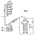
- FIG. 2 The variant of FIG. 1 shown in FIG. 2 reflects changes that can be made in the system according to FIG. 1 in order to only allow cooling of a building, especially in hot areas with a continental climate.
- FIG. 2 the necessary replacement of the outside air heat exchanger 65 as a low-temperature heat exchanger by a room air heat exchanger for the room air to be cooled in a building is not expressly shown; However, if neither a system nor a domestic water heating system is required from a system, it can - as already mentioned - be advantageous to use air as the coolant for the absorber and the condenser of the system.
- the absorber 5 of FIG. 1 is therefore replaced in FIG. 2 by an air-cooled absorber 80; in the same way, the condensation heat is dissipated to the ambient air in a condenser 81 which is provided instead of the condenser 18.
- a fan 82 and 83 are indicated, which are driven by motors 84 and 85, respectively.
- a heat exchanger 87 is provided in the expeller 10 - instead of the burner 13. This is connected via lines 86 and 88 to a known solar collector arrangement, not shown, which in this case serves as a high-temperature heat source. Water also circulates as a heat transfer medium between the solar collectors and the heat exchanger 87 in a separate, closed circuit. The arrangement allows in zones in which cooling is primarily required; to take advantage of the mostly intense solar radiation for ice production and storage during the day and to use the 'stored ice during the night for room cooling.
- the burner 13 is kept in the system according to FIG. 2, it can be operated particularly advantageously in such a way that at night. Ice formation is stored in memory 2 cold, which is used during the day to cool the room.
- the system works as an air-cooled absorption refrigeration system, in which an ice store is present as a "cold store". The excess heat can advantageously be dissipated to the cold night air with a relatively large temperature gradient.
Landscapes
- Engineering & Computer Science (AREA)
- Physics & Mathematics (AREA)
- Mechanical Engineering (AREA)
- Thermal Sciences (AREA)
- General Engineering & Computer Science (AREA)
- Chemical & Material Sciences (AREA)
- Materials Engineering (AREA)
- Sorption Type Refrigeration Machines (AREA)
Claims (15)
Applications Claiming Priority (2)
| Application Number | Priority Date | Filing Date | Title |
|---|---|---|---|
| CH9588/78 | 1978-09-13 | ||
| CH958878A CH635415A5 (de) | 1978-09-13 | 1978-09-13 | Absorptions-waermepumpenanlage. |
Publications (2)
| Publication Number | Publication Date |
|---|---|
| EP0010551A1 EP0010551A1 (fr) | 1980-05-14 |
| EP0010551B1 true EP0010551B1 (fr) | 1981-07-01 |
Family
ID=4353540
Family Applications (1)
| Application Number | Title | Priority Date | Filing Date |
|---|---|---|---|
| EP78101197A Expired EP0010551B1 (fr) | 1978-09-13 | 1978-10-23 | Système de pompe à chaleur à absorption |
Country Status (9)
| Country | Link |
|---|---|
| US (1) | US4285209A (fr) |
| EP (1) | EP0010551B1 (fr) |
| JP (1) | JPS5541394A (fr) |
| AT (1) | AT380559B (fr) |
| CH (1) | CH635415A5 (fr) |
| DE (1) | DE2860816D1 (fr) |
| ES (1) | ES483681A1 (fr) |
| IL (1) | IL58036A (fr) |
| IT (1) | IT1163708B (fr) |
Families Citing this family (22)
| Publication number | Priority date | Publication date | Assignee | Title |
|---|---|---|---|---|
| US4532778A (en) * | 1979-11-16 | 1985-08-06 | Rocket Research Company | Chemical heat pump and chemical energy storage system |
| US4368624A (en) * | 1980-03-05 | 1983-01-18 | Matsushita Electric Industrial Company, Limited | Absorption type heat pump having indoor and outdoor radiators connected in series in a water flow circuit during heat mode |
| EP0160109B1 (fr) * | 1980-06-19 | 1989-01-18 | Sonnleitner, Ingolf | Pompe à chaleur à absorption |
| GB2088548B (en) * | 1980-11-28 | 1984-10-03 | Exxon Research Engineering Co | Thermal storage heating system |
| JPS58500376A (ja) * | 1981-03-14 | 1983-03-10 | ヨ− バイラント ゲゼルシヤフト ミツト ベシユレンクテル ハフツング ウント コンパニ− | 吸収式熱ポンプの制御法 |
| US4463570A (en) * | 1981-03-14 | 1984-08-07 | Joh. Vaillant Gmbh | Method of determining a set point for a temperature pressure controller of a heat pump |
| JPS58500333A (ja) * | 1981-03-14 | 1983-03-03 | ヨ− バイラント ゲゼルシヤフト ミツト ベシユレンクテル ハフツング ウント コンパニ− | 吸収式熱ポンプの制御法 |
| JPS588961A (ja) * | 1981-07-10 | 1983-01-19 | 株式会社日立製作所 | 吸収式ヒ−トポンプ |
| DE3207656A1 (de) * | 1982-02-15 | 1983-08-25 | Hieronimi, Ulrich, 8000 München | Sorptionsapparate und verfahren fuer ihren betrieb |
| CH659314A5 (de) * | 1982-10-27 | 1987-01-15 | Sulzer Ag | Als direkt wirkender verdampfer ausgebildeter energiespeicher. |
| ATE68257T1 (de) * | 1985-05-28 | 1991-10-15 | Zeolith Tech | Vorrichtung und verfahren zur erwaermung von wasser durch einen periodischen adsorptionsprozess. |
| JPH05264115A (ja) * | 1992-03-16 | 1993-10-12 | Matsushita Electric Ind Co Ltd | 吸収式ヒートポンプ装置 |
| US20080173723A1 (en) * | 2006-07-21 | 2008-07-24 | Igor Zhadanovsky | Steam-based hvac system |
| DE102007005930A1 (de) * | 2007-02-06 | 2008-08-07 | Efficient Energy Gmbh | Wärmepuppe, Kleinkraftwerk und Verfahren zum Pumpen von Wärme |
| CZ307561B6 (cs) * | 2007-04-18 | 2018-12-05 | imka Pavel Ĺ | Topný systém s gravitačním čerpacím zařízením a způsob gravitačního podtlakového čerpání tekutin |
| DE102008053554A1 (de) * | 2008-10-28 | 2010-04-29 | Behr Gmbh & Co. Kg | Klimasystem für ein Gebäude |
| CN102353178B (zh) * | 2011-09-01 | 2013-07-03 | 合肥益用太阳能科技有限公司 | 太阳能驱动的溴化锂吸收式制冷空调及卫生热水系统 |
| ES2512990B1 (es) * | 2013-04-23 | 2015-09-18 | Universitat Rovira I Virgili | Dispositivo de refrigeración por absorción para la producción de potencia y refrigeración |
| CN104251570B (zh) * | 2013-06-25 | 2016-08-10 | 南京三创制冷科技有限公司 | 一种空气源热泵三联供的空调机组 |
| CN105352079B (zh) * | 2015-11-24 | 2018-02-06 | 东南大学 | 一种低位热能驱动的温湿度独立处理空调系统 |
| US10941965B2 (en) * | 2018-05-11 | 2021-03-09 | Mitsubishi Electric Us, Inc. | System and method for providing supplemental heat to a refrigerant in an air-conditioner |
| CN112833382A (zh) * | 2021-03-23 | 2021-05-25 | 西安热工研究院有限公司 | 一种电厂多阶余热综合利用装置及方法 |
Family Cites Families (15)
| Publication number | Priority date | Publication date | Assignee | Title |
|---|---|---|---|---|
| US2272871A (en) * | 1938-01-10 | 1942-02-10 | Honeywell Regulator Co | Absorption heating system |
| US2298924A (en) * | 1939-07-28 | 1942-10-13 | Francis R Bichowsky | Absorption refrigeration apparatus |
| FR1042435A (fr) * | 1951-09-27 | 1953-11-02 | Perfectionnements aux groupes frigorifiques à absorption, avec application à des appareils combinés, simultanément chauffants et réfrigérants | |
| US2795115A (en) * | 1954-05-14 | 1957-06-11 | Emerson L Kumm | Absorption refrigeration |
| US2817958A (en) * | 1955-08-02 | 1957-12-31 | Wesix Electric Heater Co | Absorption system for heating or cooling a space |
| DE1544149A1 (de) * | 1964-10-19 | 1969-08-21 | Trane Co | Absorptionsmischung fuer Absorptionskuehlsystem |
| US3478530A (en) * | 1967-12-15 | 1969-11-18 | Worthington Corp | Absorption refrigeration system |
| US3605432A (en) * | 1968-01-26 | 1971-09-20 | Masaji Wada | Absorption refrigerating system |
| US3561227A (en) * | 1968-08-05 | 1971-02-09 | Judson S Swearingen | Absorption refrigeration system, method and apparatus for external circulation of absorbent |
| USRE27074E (en) | 1969-08-20 | 1971-02-23 | Refrigeration process | |
| US3626716A (en) * | 1969-10-15 | 1971-12-14 | Carrier Corp | Absorption refrigeration machine heat pump |
| DE2552538A1 (de) * | 1975-11-22 | 1977-05-26 | Hans Dipl Ing Dr Herrmann | Heizofen mit waermepumpe |
| DE2648855A1 (de) * | 1976-10-25 | 1978-04-27 | Herbst Donald | Einrichtung zur senkung der durch rauchgase bedingten waermeverluste bei einem mit oel oder gas betriebenen heizkessel |
| DE2659641C2 (de) * | 1976-12-30 | 1982-08-12 | Schneider, Christian, Dipl.-Ing., 8650 Kulmbach | Gas- oder ölbetriebene Heizanlage zur Wärmeerzeugung |
| FR2412798A1 (fr) * | 1977-08-10 | 1979-07-20 | Vaillant Sa | Thermopompe a sorption |
-
1978
- 1978-09-13 CH CH958878A patent/CH635415A5/de not_active IP Right Cessation
- 1978-10-23 EP EP78101197A patent/EP0010551B1/fr not_active Expired
- 1978-10-23 DE DE7878101197T patent/DE2860816D1/de not_active Expired
-
1979
- 1979-08-13 IL IL58036A patent/IL58036A/xx unknown
- 1979-08-27 ES ES483681A patent/ES483681A1/es not_active Expired
- 1979-08-27 JP JP10826179A patent/JPS5541394A/ja active Pending
- 1979-09-05 AT AT0587079A patent/AT380559B/de not_active IP Right Cessation
- 1979-09-07 IT IT25533/79A patent/IT1163708B/it active
- 1979-09-10 US US06/073,874 patent/US4285209A/en not_active Expired - Lifetime
Also Published As
| Publication number | Publication date |
|---|---|
| US4285209A (en) | 1981-08-25 |
| IL58036A0 (en) | 1979-12-30 |
| DE2860816D1 (en) | 1981-10-08 |
| IT7925533A0 (it) | 1979-09-07 |
| JPS5541394A (en) | 1980-03-24 |
| ATA587079A (de) | 1985-10-15 |
| CH635415A5 (de) | 1983-03-31 |
| EP0010551A1 (fr) | 1980-05-14 |
| IT1163708B (it) | 1987-04-08 |
| AT380559B (de) | 1986-06-10 |
| ES483681A1 (es) | 1980-03-01 |
| IL58036A (en) | 1983-07-31 |
Similar Documents
| Publication | Publication Date | Title |
|---|---|---|
| EP0010551B1 (fr) | Système de pompe à chaleur à absorption | |
| DE69923792T2 (de) | Chemische wärmepumpe | |
| DE3207656A1 (de) | Sorptionsapparate und verfahren fuer ihren betrieb | |
| CN110360769B (zh) | 一种具有相变能源塔的热泵系统及其换热方法 | |
| DE3209761A1 (de) | Waermepumpenanlage | |
| DE102008041715A1 (de) | Heiz- und Warmwassersystem für Gebäude | |
| DE202011003668U1 (de) | Pufferspeicher zur Aufnahme von flüssigem Medium, Wasserversorgungsanlage mit einem derartigen Pufferspeicher sowie Pufferspeichervorrichtung mit zumindest einem Pufferspeicher | |
| DE202011003667U1 (de) | Pufferspeicher zur Aufnahme von flüssigem Medium, Wasserversorgungsanlage mit einem derartigen Pufferspeicher sowie Pufferspeichervorrichtung mit zumindest einem Pufferspeicher | |
| DE2918616A1 (de) | Verfahren und vorrichtung zur optimierung der waermewirtschaft in gebaeuden mit hilfe einer waermepumpe | |
| DE2542348A1 (de) | Waermeanlage | |
| EP0091095B1 (fr) | Installation de chauffage par accumulation contenant un réservoir à sorption | |
| DE2906478A1 (de) | Thermodynamischer monoblock-boiler | |
| DE3405800C2 (de) | Verfahren zum Betreiben einer Generator-Absorptionswärmepumpen-Heizanlage für die Raumheizung und/oder Warmwasserbereitung und Generator-Absorptionswärmepumpen-Heizanlage | |
| EP0019124B1 (fr) | Pompe de chaleur et procédé pour son fonctionnement | |
| DE19622609A1 (de) | Verfahren zum Betreiben einer Wärmepumpe | |
| DE3345061A1 (de) | Verfahren zur energierueckgewinnung aus einem waermespeichermedium, das einen kristallinen feststoff in form eines stoechiometrischen hydrats bilden kann, sowie unter verwendung dieses verfahrens arbeitender energiespeicher und hiermit versehenes heizsystem, kuehlsystem und energietransformationssystem | |
| DE2509965A1 (de) | Waermepumpen zur raumheizung | |
| DE2728398A1 (de) | Verfahren und einrichtung zur waermeenergiegewinnung | |
| DE102009040842A1 (de) | Hocheffizientes, solarunterstütztes Brennwert-Speicherheizgerät für flüssige oder gasförmige Brennstoffe zur Erzeugung von Trinkwarmwasser und Heizwärme zur Raumheizung | |
| DE102004061441B4 (de) | Wärmepumpe | |
| EP0079452A1 (fr) | Accumulateur d'énergie pour le stockage de chaleur latente en substances d'accumulation réagissant chimiquement ou substances d'accumulation avec changement de phase | |
| EP1163479B1 (fr) | Utilisation d'un systeme de ventilation pour batiments | |
| DE102011005231A1 (de) | Pufferspeicher zur Aufnahme von flüssigem Medium, Wasserversorgungsanlage mit einem derartigen Pufferspeicher, Pufferspeichervorrichtung mit zumindest einem Pufferspeicher sowie Verfahren zum thermischen Aufbereiten von flüssigem Medium für eine Wasserversorgungsanlage für ein Gebäude | |
| DE2727176A1 (de) | Solare heizungs/kraftwerksanlage | |
| EP0016211A1 (fr) | Installation de recuperation de chaleur utilisable pour le chauffage au moyen d'une pompe a chaleur |
Legal Events
| Date | Code | Title | Description |
|---|---|---|---|
| AK | Designated contracting states |
Designated state(s): BE CH DE FR GB LU NL SE |
|
| PUAI | Public reference made under article 153(3) epc to a published international application that has entered the european phase |
Free format text: ORIGINAL CODE: 0009012 |
|
| AK | Designated contracting states |
Designated state(s): DE FR GB NL |
|
| 17P | Request for examination filed | ||
| GRAA | (expected) grant |
Free format text: ORIGINAL CODE: 0009210 |
|
| AK | Designated contracting states |
Designated state(s): DE FR GB NL |
|
| REF | Corresponds to: |
Ref document number: 2860816 Country of ref document: DE Date of ref document: 19811008 |
|
| PGFP | Annual fee paid to national office [announced via postgrant information from national office to epo] |
Ref country code: FR Payment date: 19841026 Year of fee payment: 7 |
|
| PGFP | Annual fee paid to national office [announced via postgrant information from national office to epo] |
Ref country code: DE Payment date: 19841030 Year of fee payment: 7 |
|
| PGFP | Annual fee paid to national office [announced via postgrant information from national office to epo] |
Ref country code: NL Payment date: 19871031 Year of fee payment: 10 |
|
| PG25 | Lapsed in a contracting state [announced via postgrant information from national office to epo] |
Ref country code: GB Effective date: 19881023 |
|
| PG25 | Lapsed in a contracting state [announced via postgrant information from national office to epo] |
Ref country code: NL Effective date: 19890501 |
|
| NLV4 | Nl: lapsed or anulled due to non-payment of the annual fee | ||
| PG25 | Lapsed in a contracting state [announced via postgrant information from national office to epo] |
Ref country code: FR Free format text: LAPSE BECAUSE OF NON-PAYMENT OF DUE FEES Effective date: 19890630 |
|
| PG25 | Lapsed in a contracting state [announced via postgrant information from national office to epo] |
Ref country code: DE Effective date: 19890701 |
|
| GBPC | Gb: european patent ceased through non-payment of renewal fee | ||
| REG | Reference to a national code |
Ref country code: FR Ref legal event code: ST |
|
| PLBE | No opposition filed within time limit |
Free format text: ORIGINAL CODE: 0009261 |
|
| STAA | Information on the status of an ep patent application or granted ep patent |
Free format text: STATUS: NO OPPOSITION FILED WITHIN TIME LIMIT |