EP0010568A1 - Procédé et dispositif pour la camouflage d'un objet métallique, afin d'en éviter le repérage par radiomètre, par adaptation de son rayonnement propre au rayonnement ambiant - Google Patents
Procédé et dispositif pour la camouflage d'un objet métallique, afin d'en éviter le repérage par radiomètre, par adaptation de son rayonnement propre au rayonnement ambiant Download PDFInfo
- Publication number
- EP0010568A1 EP0010568A1 EP19790101795 EP79101795A EP0010568A1 EP 0010568 A1 EP0010568 A1 EP 0010568A1 EP 19790101795 EP19790101795 EP 19790101795 EP 79101795 A EP79101795 A EP 79101795A EP 0010568 A1 EP0010568 A1 EP 0010568A1
- Authority
- EP
- European Patent Office
- Prior art keywords
- radiation
- microwave
- environment
- radiation source
- range
- Prior art date
- Legal status (The legal status is an assumption and is not a legal conclusion. Google has not performed a legal analysis and makes no representation as to the accuracy of the status listed.)
- Granted
Links
- 230000005855 radiation Effects 0.000 title claims abstract description 65
- 238000000034 method Methods 0.000 title claims abstract description 11
- 230000003595 spectral effect Effects 0.000 claims abstract description 4
- 239000006096 absorbing agent Substances 0.000 claims description 15
- 239000007789 gas Substances 0.000 claims description 4
- 230000007613 environmental effect Effects 0.000 claims 1
- 230000001105 regulatory effect Effects 0.000 description 4
- 238000010586 diagram Methods 0.000 description 3
- 238000005259 measurement Methods 0.000 description 3
- 230000006978 adaptation Effects 0.000 description 2
- 239000002689 soil Substances 0.000 description 2
- 244000025254 Cannabis sativa Species 0.000 description 1
- 241000196324 Embryophyta Species 0.000 description 1
- 238000013016 damping Methods 0.000 description 1
- 230000000694 effects Effects 0.000 description 1
- 238000005516 engineering process Methods 0.000 description 1
- 238000005286 illumination Methods 0.000 description 1
- 238000009434 installation Methods 0.000 description 1
- 239000002184 metal Substances 0.000 description 1
- 230000008635 plant growth Effects 0.000 description 1
- 239000007787 solid Substances 0.000 description 1
Images


Classifications
-
- H—ELECTRICITY
- H01—ELECTRIC ELEMENTS
- H01Q—ANTENNAS, i.e. RADIO AERIALS
- H01Q17/00—Devices for absorbing waves radiated from an antenna; Combinations of such devices with active antenna elements or systems
- H01Q17/007—Devices for absorbing waves radiated from an antenna; Combinations of such devices with active antenna elements or systems with means for controlling the absorption
-
- F—MECHANICAL ENGINEERING; LIGHTING; HEATING; WEAPONS; BLASTING
- F41—WEAPONS
- F41G—WEAPON SIGHTS; AIMING
- F41G7/00—Direction control systems for self-propelled missiles
- F41G7/20—Direction control systems for self-propelled missiles based on continuous observation of target position
- F41G7/22—Homing guidance systems
- F41G7/224—Deceiving or protecting means
-
- F—MECHANICAL ENGINEERING; LIGHTING; HEATING; WEAPONS; BLASTING
- F41—WEAPONS
- F41H—ARMOUR; ARMOURED TURRETS; ARMOURED OR ARMED VEHICLES; MEANS OF ATTACK OR DEFENCE, e.g. CAMOUFLAGE, IN GENERAL
- F41H3/00—Camouflage, i.e. means or methods for concealment or disguise
-
- F—MECHANICAL ENGINEERING; LIGHTING; HEATING; WEAPONS; BLASTING
- F41—WEAPONS
- F41J—TARGETS; TARGET RANGES; BULLET CATCHERS
- F41J2/00—Reflecting targets, e.g. radar-reflector targets; Active targets transmitting electromagnetic or acoustic waves
- F41J2/02—Active targets transmitting infrared radiation
-
- G—PHYSICS
- G01—MEASURING; TESTING
- G01S—RADIO DIRECTION-FINDING; RADIO NAVIGATION; DETERMINING DISTANCE OR VELOCITY BY USE OF RADIO WAVES; LOCATING OR PRESENCE-DETECTING BY USE OF THE REFLECTION OR RERADIATION OF RADIO WAVES; ANALOGOUS ARRANGEMENTS USING OTHER WAVES
- G01S1/00—Beacons or beacon systems transmitting signals having a characteristic or characteristics capable of being detected by non-directional receivers and defining directions, positions, or position lines fixed relatively to the beacon transmitters; Receivers co-operating therewith
Definitions
- the invention relates to a method and a device for adapting the natural radiation of a metallic object to the radiation of its surroundings in the microwave range, predominantly in the range of the atmospheric windows around 20, 35 and 95 GHz.
- Broadband interference sources are known for military applications, which plug the receivers of active radar systems with high signal amplitudes and thereby prevent the correct reception of the echo pulses from the target.
- “intelligent” interferers which operate in the narrowband band on the frequency range of the radar device and, by means of time-synchronized interference pulses, simulate false targets.
- transponders that receive signals from the radar device, amplify them and send them back with a defined delay in the direction of the radar device and thus also simulate the presence of several targets in the radar receiver.
- microwave technology are so-called radar absorbers, with which the surface of a target can be covered and which impinges the microwave radiation with a Absorb a high degree of damping and greatly reduce backscatter. All of these methods are used in the opponent's active radar systems, in which reflected transmitter radiation is used for target location and measurement.
- the military object reflects the microwave radiation from the sky at a temperature of 30 ° K at 35 GHz and 100 ° K at 95 GHz, while the environment emits as a blackbody with the ambient temperature.
- the military object behaves like a very cold target in a warm environment (temperature contrast between 240 ° K and 280 ° K) and can be located as a cold body with a microwave radiometer. With cloudy skies and rain, the temperature contrast is reduced; however, it is still high enough to be able to locate armored vehicles with a passive microwave seeker for the final phase guidance of projectiles and missiles.
- the object of the present invention is to reduce the temperature contrast to such an extent that it is not possible to locate a metallic military object in the microwave range selected in each case.
- This object is achieved according to the invention in that the degree of vegetation, the ambient temperature and the degree of cloud cover in the vicinity of the metallic object be determined and the object is assigned a microwave radiation source, the output power of which is designed such that the sum of the radiation components of the natural radiation of the object and the radiation of the microwave radiation source in at least one of the selected spectral ranges together with the reflected sky radiation is approximately equal to the radiation of the vegetated environment.
- the temperature contrast of the camouflaged object will be used to combat it with projectiles and missiles, the dimensions of which do not allow the use of a large antenna in the three microwave ranges mentioned, so that the beam sharpness of the antenna is not sufficient to within range of a few hundred meters to receive radiation from the target or parts of the target. There will always be portions of the ambient radiation that reduce the target / background contrast. In order to keep this contrast reduction as small as possible, the short-wave range around 95 GHz is preferred to the other ranges.
- the antenna bundling is still insufficient, so that, according to a further inventive idea, it is possible to install, as an active micro-radiation source, a spherical emitter on the vehicle to be camouflaged, the radiation energy of which is emitted in spherical waves, the vehicle from all angles, including projectiles and missiles can fly to, camouflage.
- a spherical emitter on the vehicle to be camouflaged, the radiation energy of which is emitted in spherical waves, the vehicle from all angles, including projectiles and missiles can fly to, camouflage.
- passive camouflage means if one takes advantage of the fact that radar absorbers emit in the same wavelength range in which they absorb.
- Fig. 1 the emission or resp. Reflection behavior of the target 1, the clear and cloudy sky 2 and the vegetated environment 3 are shown.
- the thin arrows 5 indicate the radiation emission from the sky, which is significantly lower due to the significantly lower radiation temperature of 30 ° K to 100 ° K
- L for the guarded soil is independent of the cloud cover and thus the temperature of the sky
- the blue sky with a temperature of about 30 ° K causes a deeper cut in the sky radiation reflected from the target (solid curve 9) than in the cloudy Sky with a temperature of around 100 ° K (dashed curve 10).
- the schematic illustration shows a large radiation difference between target remission radiation and emission radiation from the vegetation. As already mentioned, this radiation contrast can be used in a passive microwave seeker head for locating the military object 1.
- FIG. 2b shows the amplitude profile of the radiation L e , in which the gap 11 is filled by active or passive camouflage measures and the radiometer 7 (FIG. 1) is offered a largely constant radiation density over the target and overgrown soil.
- the interference radiator 12 for. B. a microwave omnidirectional, mounted on the turret of the tank 1 and emits the interference radiation in all directions of the upper half space evenly, as indicated by the star-shaped arrows 13.
- the radiation density of the half space above the tank is adapted to the ambient radiation density by the interference radiator.
- FIG. 4a The schematic representation of the mode of action of a heated microwave absorber 12 'in FIG. 4a again shows - symbolized by the arrows 13 - the radiation emission of the microwave energy, which can be regulated by the flow rate and the temperature of the exhaust gases entering at 14 and exiting at 15. In another embodiment, the emission can also be controlled with the aid of an electric heater.
- the absorber surface 16 is designed to absorb for the selected microwave range.
- Fig. 4b the assembly of the absorber surfaces 17 in the form of plates is shown as an example near the exhaust system of the tank 1. It is sufficient if the absorbers cover only a part of the surface of the tank, provided that the surface temperature is chosen so high that the radiation density L e is equal to that of the surroundings.
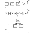
- the microwave radiation source 12 in the form of an active spherical emitter according to FIG. 3 is composed of the broadband microwave noise generator 17 for the selected spectral range and the downstream one, as regards its optronic components - as shown in the block diagram in FIG. 5 Filters 18 for the selected microwave range and the adjustable attenuator 19 together.
- the omnidirectional antenna 21 is fed via the post-amplifier 20.
- the setting of the attenuator for regulating the radiation and illumination density can - as in Fig. 5 - be done manually based on experience. However, as in FIG. 6, it can also be regulated automatically by the control unit 22. It receives the most important parameters for the setting of the sensors 23 and 24 provided for the ambient temperature and the degree of cloud cover. These sensors determine the radiation difference between the target and the background and feed it to the attenuator 19 as a manipulated variable. In other exemplary embodiments, other parameters can also be used for the control in order to optimize the adaptation process of the target to the environment, without thereby exceeding the scope of the invention. The effort is determined by the cost effectiveness and the importance of the target to be camouflaged.
Landscapes
- Engineering & Computer Science (AREA)
- General Engineering & Computer Science (AREA)
- Remote Sensing (AREA)
- Physics & Mathematics (AREA)
- Radar, Positioning & Navigation (AREA)
- Chemical & Material Sciences (AREA)
- General Physics & Mathematics (AREA)
- Combustion & Propulsion (AREA)
- Computer Networks & Wireless Communication (AREA)
- Electromagnetism (AREA)
- Radar Systems Or Details Thereof (AREA)
- Aiming, Guidance, Guns With A Light Source, Armor, Camouflage, And Targets (AREA)
- Radiation Pyrometers (AREA)
- Constitution Of High-Frequency Heating (AREA)
Applications Claiming Priority (2)
| Application Number | Priority Date | Filing Date | Title |
|---|---|---|---|
| DE2848072 | 1978-11-06 | ||
| DE19782848072 DE2848072C2 (de) | 1978-11-06 | 1978-11-06 | Verfahren und Vorrichtung zur Anpassung der Eigenstrahlung eines metallischen Zieles an die Abstrahlung seiner Umgebung |
Publications (2)
| Publication Number | Publication Date |
|---|---|
| EP0010568A1 true EP0010568A1 (fr) | 1980-05-14 |
| EP0010568B1 EP0010568B1 (fr) | 1982-12-01 |
Family
ID=6053973
Family Applications (1)
| Application Number | Title | Priority Date | Filing Date |
|---|---|---|---|
| EP19790101795 Expired EP0010568B1 (fr) | 1978-11-06 | 1979-06-07 | Procédé et dispositif pour la camouflage d'un objet métallique, afin d'en éviter le repérage par radiomètre, par adaptation de son rayonnement propre au rayonnement ambiant |
Country Status (2)
| Country | Link |
|---|---|
| EP (1) | EP0010568B1 (fr) |
| DE (1) | DE2848072C2 (fr) |
Cited By (10)
| Publication number | Priority date | Publication date | Assignee | Title |
|---|---|---|---|---|
| WO1990010928A1 (fr) * | 1989-03-16 | 1990-09-20 | Laukien Guenther | Procede pour agir sur la source des bruits emis par des sous-marins, et sous-marin |
| EP0413690A4 (en) * | 1988-01-04 | 1991-11-27 | The Commonwealth Of Australia | Infrared signature control mechanism |
| FR2669994A1 (fr) * | 1986-12-20 | 1992-06-05 | Dornier System Gmbh | Dispositif de camouflage d'objets vis-a-vis de la reconnaissance multispectrale. |
| EP0503506A1 (fr) * | 1991-03-08 | 1992-09-16 | Buck Werke GmbH & Co | Dispositif pour protéger les avions contre les missiles munis d'un autodirecteur du type UV |
| EP0533169A1 (fr) * | 1991-09-18 | 1993-03-24 | Buck Werke GmbH & Co | Procédé et aménagement pour la protection d'un bateau contre les missiles ayant des détecteurs infra-rouges à fréquence double |
| BE1006541A3 (fr) * | 1991-07-05 | 1994-10-11 | Buck Chem Tech Werke | Leurre multispectral. |
| WO1998036234A1 (fr) * | 1997-02-12 | 1998-08-20 | Schweizerische Eidgenossenschaft, Eidgenössisches Militärdepartement, Gruppe Rüstung | Structure de camouflage |
| FR2827669A1 (fr) * | 2001-07-19 | 2003-01-24 | Louis Jobert | Process industriel ayant trait a l'utilisation dynamique de la peinture pour application militaire et civile |
| CN113625273A (zh) * | 2021-06-29 | 2021-11-09 | 西安电子科技大学 | 混叠数字信号合成孔径定位方法 |
| CN119555232A (zh) * | 2024-11-06 | 2025-03-04 | 北京无线电计量测试研究所 | 一种针对地基微波辐射计的土壤辐射屏蔽装置及方法 |
Families Citing this family (12)
| Publication number | Priority date | Publication date | Assignee | Title |
|---|---|---|---|---|
| DE3135586A1 (de) * | 1981-09-09 | 1983-03-31 | Messerschmitt-Bölkow-Blohm GmbH, 8000 München | Tarnvorrichtung an fahrzeugen gegen erkennung |
| DE3217977A1 (de) * | 1982-05-13 | 1983-11-17 | Bundesrepublik Deutschland, vertreten durch den Bundesminister der Verteidigung, dieser vertreten durch den Präsidenten des Bundesamtes für Wehrtechnik und Beschaffung, 5400 Koblenz | Vorrichtung zur tarnung von objekten gegen eine aufklaerung durch waermebildgeraete |
| US5065026A (en) * | 1984-02-16 | 1991-11-12 | The United States Of America As Represented By The Secretary Of The Army | Thermal black-hole mask |
| US4609034A (en) * | 1984-04-17 | 1986-09-02 | Grumman Aerospace Corporation | Infrared camouflage system |
| US4743904A (en) * | 1986-05-22 | 1988-05-10 | The United States Of America As Represented By The Secretary Of The Army | Military countermeasures passive signature cancellation system |
| US4801113A (en) * | 1987-09-24 | 1989-01-31 | Grumman Aerospace Corporation | Apparatus and method for electrical heating of aircraft skin for background matching |
| US6435454B1 (en) * | 1987-12-14 | 2002-08-20 | Northrop Grumman Corporation | Heat pipe cooling of aircraft skins for infrared radiation matching |
| DE3804991C1 (de) * | 1988-02-18 | 1999-07-08 | Lfk Gmbh | Einrichtung zum Schutz von Aktiv-Panzerungen |
| DE4406227C1 (de) * | 1994-02-03 | 1995-10-12 | Daimler Benz Aerospace Ag | Vorrichtung zur Tarnung von Objekten |
| RU2214578C1 (ru) * | 2002-01-31 | 2003-10-20 | Федеральное государственное унитарное предприятие "Всероссийский научно-исследовательский институт "Градиент" | Система адаптивной компенсации радиометрического контраста наземных объектов |
| RU2285940C2 (ru) * | 2005-01-11 | 2006-10-20 | ОАО "Уральское проектно-конструкторское бюро "Деталь" | Способ измерения радиометрических контрастов целей и радиометр для его реализации |
| CN110826209B (zh) * | 2019-10-30 | 2021-08-06 | 北京师范大学 | 一种对植被覆盖度的影响因子贡献率估算方法及系统 |
Citations (6)
| Publication number | Priority date | Publication date | Assignee | Title |
|---|---|---|---|---|
| DE1090728B (de) * | 1956-02-08 | 1960-10-13 | Telefunken Gmbh | Anordnung zur Veraenderung des Rueckstrahlvermoegens von Reflektoren fuer ultrakurze Wellen, vorzugsweise des Zentimetergebietes, mit Hilfe einer optischen Lichtquelle |
| US3127608A (en) * | 1956-08-06 | 1964-03-31 | Gen Electric | Object camouflage method and apparatus |
| US3305863A (en) * | 1965-10-22 | 1967-02-21 | Jacobs Harold | Variable reflector of electromagnetic radiation |
| US3309704A (en) * | 1965-09-07 | 1967-03-14 | North American Aviation Inc | Tunable absorber |
| US3339201A (en) * | 1962-02-21 | 1967-08-29 | Dreiss Uwe | Decoy arrangement for a flying body |
| FR2131929A1 (fr) * | 1971-04-06 | 1972-11-17 | Barracudaverken Ab |
Family Cites Families (1)
| Publication number | Priority date | Publication date | Assignee | Title |
|---|---|---|---|---|
| DE7102973U (de) * | 1971-01-27 | 1971-07-29 | Rocholl M | Waermetarnung |
-
1978
- 1978-11-06 DE DE19782848072 patent/DE2848072C2/de not_active Expired
-
1979
- 1979-06-07 EP EP19790101795 patent/EP0010568B1/fr not_active Expired
Patent Citations (6)
| Publication number | Priority date | Publication date | Assignee | Title |
|---|---|---|---|---|
| DE1090728B (de) * | 1956-02-08 | 1960-10-13 | Telefunken Gmbh | Anordnung zur Veraenderung des Rueckstrahlvermoegens von Reflektoren fuer ultrakurze Wellen, vorzugsweise des Zentimetergebietes, mit Hilfe einer optischen Lichtquelle |
| US3127608A (en) * | 1956-08-06 | 1964-03-31 | Gen Electric | Object camouflage method and apparatus |
| US3339201A (en) * | 1962-02-21 | 1967-08-29 | Dreiss Uwe | Decoy arrangement for a flying body |
| US3309704A (en) * | 1965-09-07 | 1967-03-14 | North American Aviation Inc | Tunable absorber |
| US3305863A (en) * | 1965-10-22 | 1967-02-21 | Jacobs Harold | Variable reflector of electromagnetic radiation |
| FR2131929A1 (fr) * | 1971-04-06 | 1972-11-17 | Barracudaverken Ab |
Cited By (14)
| Publication number | Priority date | Publication date | Assignee | Title |
|---|---|---|---|---|
| FR2669994A1 (fr) * | 1986-12-20 | 1992-06-05 | Dornier System Gmbh | Dispositif de camouflage d'objets vis-a-vis de la reconnaissance multispectrale. |
| EP0413690A4 (en) * | 1988-01-04 | 1991-11-27 | The Commonwealth Of Australia | Infrared signature control mechanism |
| US5208784A (en) * | 1989-03-16 | 1993-05-04 | Laukien Guenther | Method for influencing an acoustic source, in particular of a submerged submarine, and submarine |
| WO1990010928A1 (fr) * | 1989-03-16 | 1990-09-20 | Laukien Guenther | Procede pour agir sur la source des bruits emis par des sous-marins, et sous-marin |
| EP0503506A1 (fr) * | 1991-03-08 | 1992-09-16 | Buck Werke GmbH & Co | Dispositif pour protéger les avions contre les missiles munis d'un autodirecteur du type UV |
| US5158351A (en) * | 1991-03-08 | 1992-10-27 | Buck Werke Gmbh & Company | Method for the protection of aircrafts against flying objects comprising uv-homing heads |
| BE1006541A3 (fr) * | 1991-07-05 | 1994-10-11 | Buck Chem Tech Werke | Leurre multispectral. |
| EP0533169A1 (fr) * | 1991-09-18 | 1993-03-24 | Buck Werke GmbH & Co | Procédé et aménagement pour la protection d'un bateau contre les missiles ayant des détecteurs infra-rouges à fréquence double |
| WO1998036234A1 (fr) * | 1997-02-12 | 1998-08-20 | Schweizerische Eidgenossenschaft, Eidgenössisches Militärdepartement, Gruppe Rüstung | Structure de camouflage |
| US6605340B1 (en) | 1997-02-12 | 2003-08-12 | Schweizerische Eidgenossenschaft | Camouflage structure |
| FR2827669A1 (fr) * | 2001-07-19 | 2003-01-24 | Louis Jobert | Process industriel ayant trait a l'utilisation dynamique de la peinture pour application militaire et civile |
| CN113625273A (zh) * | 2021-06-29 | 2021-11-09 | 西安电子科技大学 | 混叠数字信号合成孔径定位方法 |
| CN113625273B (zh) * | 2021-06-29 | 2023-12-22 | 西安电子科技大学 | 混叠数字信号合成孔径定位方法 |
| CN119555232A (zh) * | 2024-11-06 | 2025-03-04 | 北京无线电计量测试研究所 | 一种针对地基微波辐射计的土壤辐射屏蔽装置及方法 |
Also Published As
| Publication number | Publication date |
|---|---|
| DE2848072A1 (de) | 1980-05-14 |
| EP0010568B1 (fr) | 1982-12-01 |
| DE2848072C2 (de) | 1984-05-03 |
Similar Documents
| Publication | Publication Date | Title |
|---|---|---|
| EP0010568B1 (fr) | Procédé et dispositif pour la camouflage d'un objet métallique, afin d'en éviter le repérage par radiomètre, par adaptation de son rayonnement propre au rayonnement ambiant | |
| DE3430888C2 (fr) | ||
| DE3854795T2 (de) | Radarsystem mit einer Gruppe von untereinander verbundenen Elementar-Satelliten | |
| DE69218305T2 (de) | Ultrabreitband-Radar mit kurzen, synthetisierten Pulsen | |
| DE69514560T2 (de) | Verfahren zur Bewertung der Bildqualität bei einem Radar mit synthetischer Apertur | |
| DE2643175A1 (de) | Raketenfuehrungssystem | |
| DE3731036A1 (de) | Radar mit großem Augenblicks-Feldwinkel und hohem Augenblicks-Winkelauflösungsvermögen, insbesondere für ein Flugkörper-Zielsuchgerät | |
| EP0412441A2 (fr) | Radar multifonction | |
| EP0355336B1 (fr) | Système radar pour la détermination de la position de deux ou plusieurs objets | |
| DE3248879A1 (de) | Verfahren und vorrichtung zur erzeugung kuenstlicher zielmarken in der abbildung eines radars mit synthetischer apertur (sar) | |
| EP4226179B1 (fr) | Procédé pour détecter un missile équipé d'éléments de surface composés d'un métamatériau ou de matériaux à "surfaces sélectives en fréquence" | |
| DE2246844B2 (de) | Stoersignale und falschechos erzeugende einrichtung zur stoerung einer waffenleit-radaranlage | |
| DE2854844A1 (de) | Hochfrequenz-radiometriesystem | |
| DE3114600C2 (fr) | ||
| EP0291919A2 (fr) | Dispositif radar d'avion | |
| DE4229509C2 (de) | Verfahren und Einrichtung zum Schützen von Radarstationen gegen Anti-Radar-Flugkörper | |
| EP0992429B1 (fr) | Système de défense basé sur satellites et méthode pour la défense satellitaire | |
| DE3343604C2 (de) | Verfahren und Einrichtung zum Bekämpfen von Bodenzielen mittels eines radargelenkten Flugkörpers | |
| DE2717850C2 (de) | Radaranlage zur Erfassung von in geringer Flughöhe über einer reflektierenden Fläche fliegenden Zielen | |
| DE2455341C3 (de) | Verfahren zur Ermittlung des Windprofiles von Höhenwinden | |
| DE1541480A1 (de) | Verfahren und Vorrichtung zur radioelektrischen Untersuchung des Raumes | |
| DE2622419C3 (de) | Einrichtung zur Verhinderung absichtlicher Störungen von drahtlosen Ortungsund Kommandoübertragungssystemen durch Aussendung systemunabhängiger Signale | |
| EP0515872A2 (fr) | Appareil capteur pour déclencher une munition | |
| DE3540808A1 (de) | Einrichtung zur detektion und bekaempfung untergezogener bodenziele | |
| DE102013014192A1 (de) | Verfahren zum Schützen eines Schutzobjekts |
Legal Events
| Date | Code | Title | Description |
|---|---|---|---|
| PUAI | Public reference made under article 153(3) epc to a published international application that has entered the european phase |
Free format text: ORIGINAL CODE: 0009012 |
|
| AK | Designated contracting states |
Designated state(s): BE CH FR GB IT NL SE |
|
| 17P | Request for examination filed |
Effective date: 19800624 |
|
| ITF | It: translation for a ep patent filed | ||
| GRAA | (expected) grant |
Free format text: ORIGINAL CODE: 0009210 |
|
| AK | Designated contracting states |
Designated state(s): BE CH FR GB IT NL SE |
|
| ET | Fr: translation filed | ||
| PGFP | Annual fee paid to national office [announced via postgrant information from national office to epo] |
Ref country code: CH Payment date: 19840515 Year of fee payment: 6 |
|
| PGFP | Annual fee paid to national office [announced via postgrant information from national office to epo] |
Ref country code: SE Payment date: 19840630 Year of fee payment: 6 |
|
| PGFP | Annual fee paid to national office [announced via postgrant information from national office to epo] |
Ref country code: FR Payment date: 19840702 Year of fee payment: 6 |
|
| PGFP | Annual fee paid to national office [announced via postgrant information from national office to epo] |
Ref country code: BE Payment date: 19840930 Year of fee payment: 6 |
|
| PG25 | Lapsed in a contracting state [announced via postgrant information from national office to epo] |
Ref country code: BE Effective date: 19850630 |
|
| PGFP | Annual fee paid to national office [announced via postgrant information from national office to epo] |
Ref country code: NL Payment date: 19850630 Year of fee payment: 7 |
|
| BERE | Be: lapsed |
Owner name: ELTRO G.M.B.H. G. FUR STRAHLUNGSTECHNIK Effective date: 19850607 |
|
| PG25 | Lapsed in a contracting state [announced via postgrant information from national office to epo] |
Ref country code: SE Effective date: 19860608 |
|
| PG25 | Lapsed in a contracting state [announced via postgrant information from national office to epo] |
Ref country code: CH Effective date: 19860630 |
|
| PG25 | Lapsed in a contracting state [announced via postgrant information from national office to epo] |
Ref country code: NL Effective date: 19870101 |
|
| NLV4 | Nl: lapsed or anulled due to non-payment of the annual fee | ||
| REG | Reference to a national code |
Ref country code: CH Ref legal event code: PL |
|
| GBPC | Gb: european patent ceased through non-payment of renewal fee | ||
| PG25 | Lapsed in a contracting state [announced via postgrant information from national office to epo] |
Ref country code: GB Effective date: 19881118 |
|
| PG25 | Lapsed in a contracting state [announced via postgrant information from national office to epo] |
Ref country code: FR Free format text: LAPSE BECAUSE OF NON-PAYMENT OF DUE FEES Effective date: 19900228 |
|
| REG | Reference to a national code |
Ref country code: FR Ref legal event code: ST |
|
| EUG | Se: european patent has lapsed |
Ref document number: 79101795.7 Effective date: 19870504 |
|
| PLBE | No opposition filed within time limit |
Free format text: ORIGINAL CODE: 0009261 |
|
| STAA | Information on the status of an ep patent application or granted ep patent |
Free format text: STATUS: NO OPPOSITION FILED WITHIN TIME LIMIT |