EP0015837A2 - Antenne mit parallelen Flächen und Polarisationsdrehung - Google Patents
Antenne mit parallelen Flächen und Polarisationsdrehung Download PDFInfo
- Publication number
- EP0015837A2 EP0015837A2 EP80400285A EP80400285A EP0015837A2 EP 0015837 A2 EP0015837 A2 EP 0015837A2 EP 80400285 A EP80400285 A EP 80400285A EP 80400285 A EP80400285 A EP 80400285A EP 0015837 A2 EP0015837 A2 EP 0015837A2
- Authority
- EP
- European Patent Office
- Prior art keywords
- antenna
- parallel
- plane
- parallel planes
- planes according
- Prior art date
- Legal status (The legal status is an assumption and is not a legal conclusion. Google has not performed a legal analysis and makes no representation as to the accuracy of the status listed.)
- Withdrawn
Links
Images


Classifications
-
- H—ELECTRICITY
- H01—ELECTRIC ELEMENTS
- H01Q—ANTENNAS, i.e. RADIO AERIALS
- H01Q19/00—Combinations of primary active antenna elements and units with secondary devices, e.g. with quasi-optical devices, for giving the antenna a desired directional characteristic
- H01Q19/10—Combinations of primary active antenna elements and units with secondary devices, e.g. with quasi-optical devices, for giving the antenna a desired directional characteristic using reflecting surfaces
- H01Q19/18—Combinations of primary active antenna elements and units with secondary devices, e.g. with quasi-optical devices, for giving the antenna a desired directional characteristic using reflecting surfaces having two or more spaced reflecting surfaces
- H01Q19/19—Combinations of primary active antenna elements and units with secondary devices, e.g. with quasi-optical devices, for giving the antenna a desired directional characteristic using reflecting surfaces having two or more spaced reflecting surfaces comprising one main concave reflecting surface associated with an auxiliary reflecting surface
- H01Q19/195—Combinations of primary active antenna elements and units with secondary devices, e.g. with quasi-optical devices, for giving the antenna a desired directional characteristic using reflecting surfaces having two or more spaced reflecting surfaces comprising one main concave reflecting surface associated with an auxiliary reflecting surface wherein a reflecting surface acts also as a polarisation filter or a polarising device
-
- H—ELECTRICITY
- H01—ELECTRIC ELEMENTS
- H01Q—ANTENNAS, i.e. RADIO AERIALS
- H01Q13/00—Waveguide horns or mouths; Slot antennas; Leaky-waveguide antennas; Equivalent structures causing radiation along the transmission path of a guided wave
- H01Q13/02—Waveguide horns
Definitions
- the invention relates to an antenna with parallel planes of the Pill-Box type or of the "cheese” or “cheese” type in English.
- antenna with parallel planes of the cheese type or of the Pill-Box type is meant an antenna essentially constituted by two parallel plates limited by a cylindro-parabolic bottom illuminated by a source placed on its focal right, as shown in FIG. 1.
- the source can be a simple singlemode horn or a multimode source.
- the TEM, TE and TM modes are possible, the TEM, TE and TM modes. Details on this type of antenna are given in "Les Antennes" by L. THOUREL, published by Dunod, page 285, edition 1976, and in "Microwave ⁇ ntenna Theory and Design", Tome 12, page 459 of the Radiation Laboratories Collection Series (1949 edition).
- One solution to eliminate this concealment effect without increasing the depth of the antenna consists in making an antenna with parallel planes of the cheese or Pill-Box type, folded in accordance with FIG. 2, where the feed is separated from the part radiant.
- This antenna consists of two Pill-Boxes or two "cheeses” 41 and 43 coupled together by a slot 44 running all along the parabolic bottom common to the two antennas.
- the slot 44 is dimensioned so that the assembly formed by the two cheeses 41 and 43 and the slot 44 constitutes a suitable folded guide.
- the present invention overcomes these drawbacks and relates to an antenna with parallel planes of the "cheese” or “Pill-Box” type, fed from the rear and with polarization rotation.
- the antenna with parallel planes comprises a cylindro-parabolic bottom consisting of a semi-transparent reflector and a plane containing the focal line of the antenna consisting of a polarizing reflector.
- One of the advantages of the invention is the reduction in the actual focal distance of the antenna, therefore in the longitudinal dimensions and therefore in the volume and the weight of the antenna to be driven, thanks to the folding of the optical path produced at using the two reflectors.
- the semi-transparent cylindro-parabolic reflector has a large equivalent focal length allowing the use of sources capable of exciting the antenna with parallel planes under usual conditions of use.
- Another advantage of the invention is the production of an antenna with parallel planes, the excitation source of which is placed at the rear.
- FIG. 3 representing an example of embodiment of an antenna with parallel planes according to the invention, in addition to FIGS. 1 and 2 respectively representing an antenna with conventional parallel planes and a folded parallel plane antenna.
- FIG. 1 represents an antenna with conventional parallel planes. It consists of two parallel plates limited by a cylindrical-parabolic bottom 2, illuminated by a source 3 placed on its focal line F.
- the source 3 is either a single-mode horn or a multimode source.
- the mouth of the horn constitutes a linear source equiphase and according to the height H separating the two parallel plates 1, several modes of operation can exist. If the height H is less than half the wavelength at the center frequency of the operating band, n / 2, only TEM mode can exist.
- the aerial is then most often called the "Pill-Box" antenna. If the height H is greater than ⁇ / 2, the TE and TM modes can propagate, and the aerial is said to be a "cheese” antenna.
- FIG. 2 Another type of embodiment of an antenna with parallel Pill-Box or cheese faces is shown in FIG. 2.
- the power source 40 of the antenna is separated from the radiating part 41 by a partition 42 between the feeding 43 and radiating 41 parts.
- this Pill-Box or folded cheese antenna is constituted by two Pill-Box antennas or two "cheese” antennas coupled by a slot 44 which runs all along the parabolic bottom 45.
- the part 43 of the folded antenna is excited by the source 40, a horn for example.
- the slot 44 is dimensioned so that the assembly formed by it and the two cheeses 41 and 43 is a suitable folded guide. This system above all gives good results with a TEM mode.
- FIG. 3 represents an antenna with parallel planes according to the invention. It is constituted by two parallel plates 8 and 9 limited on the one hand by a semi-transparent reflective cylindrical-parabolic bottom 10 and on the other hand by a plane polarizer reflector assembly 11 perpendicular to the plates 8 and 9 and containing the focal line F of the antenna.
- the semi-transparent cylindro-parabolic reflector 10 is formed by a network of wires 12 parallel to the plane of polarization of the wave emitted by the source 13.
- This plane reflector assembly 11 is formed by a reflective plate 14, and by a network 15 son 16 parallel to each other and forming an angle of 45 ° with the plane of polarization of the wave emitted by the source, this assembly ensuring a rotation of polarization.
- the distance between the plate 14 and the network 15 is substantially equal to a quarter of the wavelength, rv4, to the central frequency of the operating band, this condition not being imperative if one wishes to work in a wide range. bandaged.
- Metal plates 17, 18, 19 and 20 constitute, with the planar reflector assembly 11, a rectangular parallelepiped box.
- the wave emitted by the source 13, then reflected by the semi-transparent cylindro-parabolic reflector 10 can be broken down in two orthogonal directions, a first component being parallel to the wires 16 and a second component being perpendicular to the wires 16.
- the component perpendicular to the wires 16 crosses the grating and is reflected by the reflecting plate 14.
- the parallel component does not cross the grating 15 and is reflected.
- the perpendicular component is 180 ° out of phase with respect to the parallel component after being reflected on the reflective plate 14 and having crossed the network of wires 16.
- This phase delay has the effect of rotating the plane of polarization of the resulting wave radiated a second time by the plane reflector assembly 11 towards the semi-transparent cylindro-parabolic reflector 10.
- the cylindro-parabolic reflector 10 has become transparent for this incident wave, the polarization plane of which has rotated 90 ° relative to the wave emitted by the source 13, the electric field vector of the emitted wave being perpendicular to the parallel wires of the network 12 carried by the cylindro-parabolic reflector 10.
- the two networks of parallel wires 12 and 16 can be replaced by parallel reflecting plates or by wires embedded in a glass-resin complex.
- FIG. 4 Another embodiment of an antenna with parallel “cheese” or Pill-Box planes is shown in FIG. 4.
- the bottom consists of the flat reflector assembly 11 and having for sides perpendicular to the bottom the metal plates 22, 23, 24 and 25.
- the metal plates 22 and 24, perpendicular to the bottom, constitute the two parallel plates 8 and 9 of the antenna.
- the bottom of the box is formed by the reflecting plate 14 located at ⁇ / 4 from the network 15 of wires parallel to each other, making an angle of 45 ° with the plane of polarization of the wave emitted by the source, and is lit by the source 13 placed in the center of the radiant background towards the inside.
- An opening 26 is made on the entire face opposite the reflective bottom and may have a flared part in the shape of a horn 27 to improve the directivity.
- the network 10 of parallel wires placed on a surface of cylindro-parabolic shape is placed to make the semi-transparent cylindro-parabolic reflector of the antenna.
- edges 29 and 28 of the cylindrical-parabolic network 10 are not in the focal plane, but form with it a non-zero angle 2.
- the fact of closing these edges with solid metal plates 30 and 31 on the focal plane makes it possible to substantially increase the gain of the antenna.
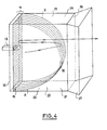
- This variant is also applicable to the case of the antenna placed in a parallelepiped box as shown in Figure 6.
- edges 32 and 33 of the network cylindro-parabolic 10 make an angle ( ⁇ not zero with the focal line F.
- the antenna, object of the invention has a reduced bulk along the axis. focal point of the antenna; hence a reduction in volume and weight while retaining radioelectric characteristics in accordance with those given by a conventional parallel plane antenna.
- These antennas with parallel planes according to the invention can be used as surveillance and objective designation antennas. They have the same functions as the antennas with parallel planes of the prior art, but with a reduced manufacturing cost at the level of the antenna itself and of its drive mechanisms.
Landscapes
- Aerials With Secondary Devices (AREA)
- Variable-Direction Aerials And Aerial Arrays (AREA)
Applications Claiming Priority (2)
| Application Number | Priority Date | Filing Date | Title |
|---|---|---|---|
| FR7906135 | 1979-03-09 | ||
| FR7906135A FR2451114A1 (fr) | 1979-03-09 | 1979-03-09 | Antenne a plans paralleles a rotation de polarisation |
Publications (2)
| Publication Number | Publication Date |
|---|---|
| EP0015837A2 true EP0015837A2 (de) | 1980-09-17 |
| EP0015837A3 EP0015837A3 (de) | 1980-10-01 |
Family
ID=9222978
Family Applications (1)
| Application Number | Title | Priority Date | Filing Date |
|---|---|---|---|
| EP80400285A Withdrawn EP0015837A3 (de) | 1979-03-09 | 1980-02-29 | Antenne mit parallelen Flächen und Polarisationsdrehung |
Country Status (3)
| Country | Link |
|---|---|
| US (1) | US4297710A (de) |
| EP (1) | EP0015837A3 (de) |
| FR (1) | FR2451114A1 (de) |
Cited By (2)
| Publication number | Priority date | Publication date | Assignee | Title |
|---|---|---|---|---|
| FR2590081A1 (fr) * | 1985-11-12 | 1987-05-15 | Rca Corp | Antenne a reflecteurs a grilles polarisees lineairement avec de meilleures performances de polarisation transversale |
| CN106654565A (zh) * | 2015-12-20 | 2017-05-10 | 中国电子科技集团公司第二十研究所 | 基于mimo体制相控阵的一体化超宽带偏置抛物柱面阵列天线 |
Families Citing this family (8)
| Publication number | Priority date | Publication date | Assignee | Title |
|---|---|---|---|---|
| FR2557737B1 (fr) * | 1983-12-30 | 1987-12-18 | Thomson Csf | Antenne a deux reflecteurs cylindro-paraboliques croises et son procede de fabrication |
| US4876554A (en) * | 1988-01-19 | 1989-10-24 | Qualcomm, Inc. | Pillbox antenna and antenna assembly |
| US4975712A (en) * | 1989-01-23 | 1990-12-04 | Trw Inc. | Two-dimensional scanning antenna |
| US20030103001A1 (en) * | 1991-12-10 | 2003-06-05 | Huston Charles D. | Golf distance measuring system and method |
| US6043779A (en) * | 1999-03-11 | 2000-03-28 | Ball Aerospace & Technologies Corp. | Antenna apparatus with feed elements used to form multiple beams |
| US6275196B1 (en) * | 2000-05-12 | 2001-08-14 | Idigi Technologies, Inc. | Parabolic horn antenna for wireless high-speed internet access |
| AU2002950196A0 (en) * | 2002-07-11 | 2002-09-12 | Commonwealth Scientific And Industrial Research Organisation | Real-time, cross-correlating millimetre-wave imaging system |
| TWI292234B (en) * | 2004-03-16 | 2008-01-01 | Arcadyan Technology Corp | Multi-band antenna apparatus having reflector |
Family Cites Families (4)
| Publication number | Priority date | Publication date | Assignee | Title |
|---|---|---|---|---|
| US2942266A (en) * | 1957-07-16 | 1960-06-21 | Bell Telephone Labor Inc | Antenna with means for preventing re-radiation into feed guide |
| GB1330175A (en) * | 1970-08-04 | 1973-09-12 | Elliott Brothers London Ltd | Radio aerials |
| SE356641B (de) * | 1972-04-24 | 1973-05-28 | Ericsson Telefon Ab L M | |
| US3916416A (en) * | 1974-09-24 | 1975-10-28 | Us Navy | 360{20 {0 Azimuth scanning antenna without rotating RF joints |
-
1979
- 1979-03-09 FR FR7906135A patent/FR2451114A1/fr active Pending
-
1980
- 1980-02-29 EP EP80400285A patent/EP0015837A3/de not_active Withdrawn
- 1980-03-04 US US06/127,097 patent/US4297710A/en not_active Expired - Lifetime
Cited By (2)
| Publication number | Priority date | Publication date | Assignee | Title |
|---|---|---|---|---|
| FR2590081A1 (fr) * | 1985-11-12 | 1987-05-15 | Rca Corp | Antenne a reflecteurs a grilles polarisees lineairement avec de meilleures performances de polarisation transversale |
| CN106654565A (zh) * | 2015-12-20 | 2017-05-10 | 中国电子科技集团公司第二十研究所 | 基于mimo体制相控阵的一体化超宽带偏置抛物柱面阵列天线 |
Also Published As
| Publication number | Publication date |
|---|---|
| EP0015837A3 (de) | 1980-10-01 |
| US4297710A (en) | 1981-10-27 |
| FR2451114A1 (fr) | 1980-10-03 |
Similar Documents
| Publication | Publication Date | Title |
|---|---|---|
| EP0205212B1 (de) | Modulare Mikrowellenantenneneinheiten und Antenne mit solchen Einheiten | |
| EP3547450A1 (de) | Strahlungselement mit kreispolarisierung, bei dem eine resonanz in einem fabry-perot-interferometer angewandt wird | |
| EP0057121B1 (de) | Hochfrequenz-Doppelbanderreger und eine Antenne mit einem solchen Erreger | |
| EP0015837A2 (de) | Antenne mit parallelen Flächen und Polarisationsdrehung | |
| EP0147325B1 (de) | Antenne mit zwei gekreuzten parabolisch-cylindrischen Reflektoren und Verfahren zur Herstellung derselben | |
| EP0082751A1 (de) | Mikrowellenstrahler und seine Verwendung für eine Antenne mit elektronischer Abtastung | |
| EP0074311A1 (de) | Rechteckhohlleiterschlitzantenne für breiten Frequenzbereich | |
| EP1815492A2 (de) | Mikrowellengenerator mit oszillierender virtueller kathode | |
| EP2658032B1 (de) | Hornstrahler einer Antenne mit gewelltem Gitter | |
| EP0440126A1 (de) | Antenne mit geschlitzten Hohlleitern, insbesondere für Weltraumradar | |
| EP0004215B1 (de) | Mehrmode Mikrowellenstrahler und Monopulsantenne mit einem solchen Strahler | |
| FR3069713B1 (fr) | Antenne integrant des lentilles a retard a l'interieur d'un repartiteur a base de diviseurs a guide d'ondes a plaques paralleles | |
| EP0065467B1 (de) | Mikrowellenantenne für Zirkularpolarisation | |
| EP0033676B1 (de) | Gemeinsame Antenne für Primär-Radar und Sekundär-Radar | |
| FR2613140A1 (fr) | Antenne cornet parallelepipedique a repartition du champ d'ouverture linearisee en deux polarisations | |
| FR2538959A1 (fr) | Lentille hyperfrequence bi-bande, son procede de fabrication et antenne radar bi-bande de poursuite | |
| FR2590081A1 (fr) | Antenne a reflecteurs a grilles polarisees lineairement avec de meilleures performances de polarisation transversale | |
| EP0202979A1 (de) | Polarisationsselektiver Reflektor und Verfahren zu dessen Herstellung | |
| FR3003700A1 (fr) | Dispositif de reduction de signature radar d'antenne et systeme antennaire associe | |
| FR2490025A1 (fr) | Antenne du type cornet monomode ou multimode comprenant au moins deux voies radar et fonctionnant dans le domaine des hyperfrequences | |
| EP0550320B1 (de) | Wellenleiter mit geraden strahlenden Schlitzen, angeregt durch metallische Einsätze | |
| EP0093058B1 (de) | Mikrowellen-Speisevorrichtung für rotationssymmetrischen Doppelbanderreger mit Rillen | |
| FR2507392A1 (fr) | Source rayonnante hyperfrequence a cavites ouvertes excitee par deux dipoles orthogonaux | |
| EP0109322A1 (de) | Doppelreflektorantenne für einen Nachführungsradar mit verbesserter Zielauffassung | |
| FR2470457A1 (fr) | Antenne a reseau a fentes avec distribution d'amplitude dans une petite ouverture circulaire |
Legal Events
| Date | Code | Title | Description |
|---|---|---|---|
| PUAI | Public reference made under article 153(3) epc to a published international application that has entered the european phase |
Free format text: ORIGINAL CODE: 0009012 |
|
| PUAL | Search report despatched |
Free format text: ORIGINAL CODE: 0009013 |
|
| AK | Designated contracting states |
Designated state(s): BE CH DE GB IT LU NL SE |
|
| AK | Designated contracting states |
Designated state(s): BE CH DE GB IT LU NL SE |
|
| 17P | Request for examination filed | ||
| STAA | Information on the status of an ep patent application or granted ep patent |
Free format text: STATUS: THE APPLICATION IS DEEMED TO BE WITHDRAWN |
|
| 18D | Application deemed to be withdrawn |
Effective date: 19820616 |
|
| RIN1 | Information on inventor provided before grant (corrected) |
Inventor name: DUPRESSOIR, ALBERT |