EP0016376B1 - Apparat zum Zuführen dünner Bogen - Google Patents
Apparat zum Zuführen dünner Bogen Download PDFInfo
- Publication number
- EP0016376B1 EP0016376B1 EP80101115A EP80101115A EP0016376B1 EP 0016376 B1 EP0016376 B1 EP 0016376B1 EP 80101115 A EP80101115 A EP 80101115A EP 80101115 A EP80101115 A EP 80101115A EP 0016376 B1 EP0016376 B1 EP 0016376B1
- Authority
- EP
- European Patent Office
- Prior art keywords
- pile
- feeding
- thin sheet
- rollers
- thin sheets
- Prior art date
- Legal status (The legal status is an assumption and is not a legal conclusion. Google has not performed a legal analysis and makes no representation as to the accuracy of the status listed.)
- Expired
Links
- 238000005452 bending Methods 0.000 claims description 16
- 230000009471 action Effects 0.000 claims description 2
- 230000003247 decreasing effect Effects 0.000 claims description 2
- 238000013459 approach Methods 0.000 claims 2
- 238000006073 displacement reaction Methods 0.000 claims 1
- 230000007246 mechanism Effects 0.000 description 33
- 230000004069 differentiation Effects 0.000 description 7
- 230000004044 response Effects 0.000 description 3
- 238000007493 shaping process Methods 0.000 description 3
- 239000000463 material Substances 0.000 description 2
- 239000011159 matrix material Substances 0.000 description 2
- 230000001133 acceleration Effects 0.000 description 1
- 238000003491 array Methods 0.000 description 1
- 230000005540 biological transmission Effects 0.000 description 1
- 230000008878 coupling Effects 0.000 description 1
- 238000010168 coupling process Methods 0.000 description 1
- 238000005859 coupling reaction Methods 0.000 description 1
- 238000010586 diagram Methods 0.000 description 1
- 239000011796 hollow space material Substances 0.000 description 1
- 238000000034 method Methods 0.000 description 1
- 230000008569 process Effects 0.000 description 1
Images




Classifications
-
- B—PERFORMING OPERATIONS; TRANSPORTING
- B65—CONVEYING; PACKING; STORING; HANDLING THIN OR FILAMENTARY MATERIAL
- B65H—HANDLING THIN OR FILAMENTARY MATERIAL, e.g. SHEETS, WEBS, CABLES
- B65H1/00—Supports or magazines for piles from which articles are to be separated
- B65H1/04—Supports or magazines for piles from which articles are to be separated adapted to support articles substantially horizontally, e.g. for separation from top of pile
-
- B—PERFORMING OPERATIONS; TRANSPORTING
- B65—CONVEYING; PACKING; STORING; HANDLING THIN OR FILAMENTARY MATERIAL
- B65H—HANDLING THIN OR FILAMENTARY MATERIAL, e.g. SHEETS, WEBS, CABLES
- B65H3/00—Separating articles from piles
- B65H3/46—Supplementary devices or measures to assist separation or prevent double feed
- B65H3/56—Elements, e.g. scrapers, fingers, needles, brushes, acting on separated article or on edge of the pile
Definitions
- This invention relates to a thin sheet feeding apparatus having means for supporting a pile of thin sheets piled one upon another, and means for sequentially feeding the thin sheets one by one, in a predetermined feeding direction, from the uppermost thin sheet of the pile.
- a thin sheet feeding apparatus as disclosed in FR-A-2298990 for feeding thin sheets singly and sequentially from a pile of thin sheets it has been general practice to manually remove a belt member from each pile before the pile is supplied to this thin sheet feeding apparatus.
- the pile supplied into the thin sheet feeding apparatus may be curved by means of the bottom of a corresponding casing.
- An object of this invention is to provide a thin sheet feeding apparatus which can feed at least one thin sheet at a time and sequentially from a pile of thin sheets which is bundled by a belt member and which consists of a plurality of thin sheets, without the need to remove the belt member.
- the thin sheet feeding apparatus of this invention is characterized by bending means disposed on said supporting means and serving to bend the pile bundled by a belt and supplied to said supporting means along a bending line parallel with said feeding direction, said pile being supplied to said supporting means such that the edges of the pile in contact with said belt are substantially parallel with said feeding direction, whereby the frictional force acting on said uppermost thin sheet is decreased when said sheet is fed.
- the pile when the thin sheets are being fed, the pile is curved so that each of two side faces of the thin sheets of the pile is in contact slightly with the belt.
- the frictional force exerted on the uppermost'thin sheet in feeding it is extremely small as compared to the case in which the thin sheet is fed without bending. Therefore, the uppermost thin sheet or sheets can be easily fed from the pile in the direction of feeding.
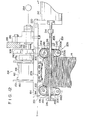
- numeral 10 denotes a thin sheet feeding apparatus according to this invention and numeral 12 signifies a feeding means for transferring piles of thin sheets 14 (which will be hereinafter referred to as piles for brevity) to the feeding apparatus 10.
- the piles 14 comprise a plurality of thin sheets 14b which are bundled by belt members 14a.
- the piles 14 are supplied to the thin sheet feeding device 10 by a belt 16a driven by a roller 16 of the feeding means.
- Numeral 18 at the right end of Fig. 1 is a transferring means for transferring each thin sheet sequentially fed by the device 10 to the right direction by placing it on a belt 18a.
- the belt 18a is driven by a roller 18b.
- the piles 14 are supplied from the left side and are fed to the right side in Fig. 1.
- the left-right direction of Fig. 1 is referred to as the longitudinal direction and is shown by X-X in the Figure.
- the direction perpendicular to the X-X direction of Fig. 1 is referred to as the lateral direction and is shown by Y-Y in the Figure.
- the direction perpendicular to the X-X and Y-Y directions, that is, the vertical direction in Fig. 1, is referred to as the vertical direction and is shown by Z-Z in the Figure.
- Fig. 2 shows the pile 14.
- Each thin sheet 14b is substantially rectangular in shape, and a plurality of them are tightly bundled by a belt member 14a.
- the thin sheets described here in this specification include any flexible sheets such as bills, securities, documents and data cards consisting of resinous films.
- the pile 14 is kept, as shown in the Figure, in bundled form by a belt member 14a which lies along a direction substantially parallel to the shorter sides of the thin sheets, and the pile 14 is supplied to the device 10 in such a manner that their long sides are in the above-mentioned longitudinal direction.
- the pile 14 has side faces 20 perpendicular to the lateral direction and side faces 22 perpendicular to the longitudinal direction.
- the side faces 20 are referred to as longitudinal side faces, and the side faces 22, lateral side faces. They are, respectively, shown at 20 and 22.
- a pile supporting means 23 for supporting the piles comprises a shifting means 30 for vertically moving the piles and a pile bending means 25 which will be described hereinafter in detail.
- the pile shifting means 30, as shown in Fig. 3, mainly includes a base plate 32; a support pole 34 standing upright thereon; a horizontal plate 36a of a carriage body 36, which is substantially horizontal to the support pole 34; and a vertically driving mechanism 38 for vertically shifting the base plate 32.
- the carriage body 36 has a horizontal plate 36a on which are placed the piles 14 supplied by the delivering means 12 and side plates 42 rotatably mounted at each of the lateral ends of the horizontal plate 36a through hinges 40.
- the side plates 42 respectively, extend laterally outward from each hinge 40 so that they open wider in the upward direction, and forming free ends 42a.
- Projections 44 extend from free ends 42a of the side plates 42 along the direction of extension of the side plates 42.
- the lower ends of the side plates 42 are supported on the horizontal plate 36, and the side plates 42 are connected to a rod 48 through link mechanisms 46.
- the rod 48 is connected to an operating rod 50a of an electromagnetic mechanism 50 secured to the base plate 32.
- the pile bending means 25 comprises the side plates 42, the link mechanism 46, the rod 48, the electromagnetic mechanism 50 and the operating rod 50a.
- a rod-shaped stopper 52 depends downward above the central part of the horizontal plate 36a as shown in Fig. 3.
- a vertically upright rotating mechanism 54 is mounted on the base plate 32 laterally away from the central portion of the horizontal plate 36a.
- a stopper supporting member 56 extends upwardly therefrom and then bends laterally, and from its front end depends the above- mentioned stopper 52.
- the rotating mechanism 54 comprises, for example, a pneumatic mechanism.
- the stopper 52 rotates about the vertical portion of the stopper supporting member 56, and stops at a position determined by a rotation interrupting member (not shown) of the mechanism 54. It is however, automatically returned to the position shown in Fig. 3 by a spring (not shown) when the driving of the rotating mechanism is interrupted.
- a suction roller 60 is disposed to the right of the stopper 52 and above the carriage body 36 in Fig. 1, and is rotated in the direciton of an arrow 60a by a suitable driving means (not shown).
- a suction hole 62 is formed in this roller 60, one end of which is open at the central surface of the roller 60 and the other end of which is communicated with a suitable suction system (not shown) through the roller 60.
- a pair of mutually coupled feed rolls 58 are disposed to the right of the roller 60, and the roller 60 and the feed rolls 58 together form a thin sheet feeding means 59.
- numeral 64 denotes a hole formed in the horizontal plate 36a.
- a light emitter 66 and a light sensor 68 are disposed above and below the hole 64 so that they are in vertical alignment.
- Numerals 70 and 72 shown above and below the base plate 32 (Fig. 3), are switching means or limit switches (70, 72) which are secured to the lift mechanism 38 and which operate when the base plate 32 reaches either a predetermined upper end portion or.- a predetermined lower end position.
- a device 80 for controlling the vertically driving mechanism 38, the electromagnetic mechanism 50, and the rotating mechanism 54 will now be described with reference to Fig. 4.
- the control device 80 may take various forms and is well known to those skilled in the art. In addition, it does not constitute an essential feature of this invention. Thus, the explanation will be brief.
- An output signal of the light sensor 68 in Fig. 4 is supplied to a differential circuit 84 after it passed through a waveform shaping circuit 82.
- the falling signal of this output signal is supplied to the S terminal, that is, the setting terminal of a flip-flop circuit 88 (which will be referred to as an FF circuit) through a delay circuit 86.
- a setting output signal produced by the FF circuit 88 turns on a switching circuit 90, and the power of a power source 92 is applied to the electromagnetic mechanism 50 through the switching circuit 90.
- the setting output signal of the FF circuit -88 is applied to the switching circuit 90 and is also applied to a changeover switch 96 through a delay circuit 94 and the limit switch 70 (Fig. 3).
- the resetting output signal is also supplied to the change-over switch 96 through the limit switch 72 (Fig. 3).
- the limit switch 70 is kept on, except when it is turned off as the base plate 32 is lifted to a predetermined position to be operated.
- the limit switch 72 is kept on, except when it is turned off as the base plate 32 is lowered to another predetermined position to be operated.
- the change-over switch 96 drives the vertically driving mechanism 38 to lift the base plate 32 and interrupts its lifting when the limit switch 70 starts operating.
- the resetting output signal of the FF circuit 88 is transmitted to the change-over switch 96 through the limit switch 72, the abovementioned switch 96 drives the vertically driving mechanism 38 to lower the base plate 32 and interrupts its lowering when the limit switch 72 starts operating.
- the vertically driving mechanism 38 operates to lift the base plate 32 when a setting signal is produced by the FF circuit and the limit switch 70 is closed, and the vertically driving mechanism 38 operates to lower the base plate 32 when a resetting signal is produced by the FF circuit and the limit switch 72 is closed.
- the output of the waveform shaping circuit 82 is supplied to the differentiation circuit 84 as well as to a differentiation circuit 100.
- the differentiation circuit 100 generates an output representative of a building up of the signal transmitted from the waveform shaping circuit 82 and supplies this signal to the resetting terminal of the FF circuit 88 and to monostable multivibrator 102.
- the monostable multivibrator 102 drives the. rotatating mechanism 54 for a predetermined period of time and transfers the stopper 52 (Fig. 3) from its position above the horizontal plate 36a for the above-mentioned predetermined period of time.
- the electromagnetic mechanism 50 is operated, the operating rod 50a is lifted, and the side plates 42 of the carriage body 36 are pivoted cbout the hinges 40 in the direction of the arrows 104 of Fig. 3.
- the width of the horizontal part 106 of the carriage body 36 is adjusted to be substantially equal to the width of the pile 14 as shown in Fig. 5.
- the upper surfaces of the side plates 42 are, as described before, curved to form gently curved faces.
- the pile 14 is lifted in slipping along the curved faces, as shown in Fig. 6.
- the center of the upper surface of the pile 14 contacts the lower end of the stopper 52.
- the pile 14 is lifted still further along the projections 44.
- the stopper 52 inhibits the lifting of the center of the upper surface
- the right and left ends of the pile 14 of Fig. 6 alone are lifted along the projections 44.
- the pile 14 thus takes a bent form. with its recessed side facing upwardly as shown in Fig. 7. That is, the pile 14 as a whole is curved as mentioned above as its longitudinal side faces 20 are clamped by the projections 44, and the belt member 14a is bent in an arc forming a convex surface at its upper side.
- a space 108 similar to the shape of a convex lens is formed between the belt member 14a and the upper surface of the pile 14. Shown in Fig.
- the lower surface of the bottommost thin sheet is in contact with the belt member 14a
- the other thin sheets contact the belt member 14a at the lower edges of their thin side faces. Accordingly, the pressing force of the belt member 14a which has been applied concentratedly to the upper portion and lower portions of the side faces of the pile 14 is diffused in the substantially whole areas by which the belt member 14a contacts with the both side faces of the bent pile.
- the frictional force between the thin sheets and the belt member 14a becomes substantially the same as when the thin sheets are not bundled by the belt member 14a.
- the uppermost thin sheet can easily be taken out with a small force when pulled in the longitudinal direction, that is, in the direction perpendicular to the plane of the thin sheets of Fig. 7. Thereafter, when a period of time determined by the delay circuit 94 elapses, a lift control signal for lifting the base plate 32 is supplied to the change-over switch 96 through the limit switch 70. The carriage body 36 is then lifted with the base plate 32 to a predetermined position wherein the roller 60 contacts the uppermost thin sheet 14c of the pile in the condition of Fig. 7. The thin sheet 14c is longitudinally displaced by the roller, is engaged with the feed rolls 58 of Fig. 9 to be transferred upwardly to the right, and is fed to a desired position through the transferring means 18. The roller 60 and the feed rolls 58 constitute the thin sheet feeding means for pulling the thin sheets from the pile 14.
- the output signal of the light sensor 68 is strong again.
- the FF circuit 88 is placed under a resetting condition.
- the switching circuit 90 is turned off, the force exerted by the electromagnetic mechanism 50 is released, and the carriage body 36 is returned to the position shown in Fig. 5.
- a lowering control signal is supplied from the change-over switch 96 to the vertically driving mechanism 38. As a result, the base plate 32 lowers until the limit switch 72 is turned off and the operation of the vertically driving mechanism 38 is interrupted.
- the output signal of the differentiation circuit 100 is also supplied to the monostable multivibrator 102 for a predetermined period of time for inverting it.
- a valve in the rotating mechanism 54 opens, and compressed air supplied therethrough displaces the stopper 52 of Figs. 1 and 3 from the center of the horizontal plate 36a.
- the belt member 14a remaining on the carriage body 36 is hooked by the lower end of the stopper 52 to be laterally displaced, and is made to fall from the stopper 52 when the stopper 52 is abruptly interrupted by another stopper (not shown) in the rotating mechanism.
- the above- mentioned valve is automatically closed.
- the stopper then returns to the position shown in Figs. 1 and 3 by the restoring force of a spring (not shown) in the rotating mechanism 54.
- the above series of operations is repeated and the thin sheets are sequentially fed by this apparatus.
- Fig. 10 is a side view illustrating the main part of the thin sheet feeding apparatus of the second embodiment.
- Numeral 122 refers to a frame of the apparatus 120.
- Bearings 126 and 128 are mounted through a support member 124 on the frame 122 in alignment with the Z-Z direction, that is, in vertical alignment.
- a vertically extending screw rod 130 is received by the bearings 126 and 128.
- the upper end of the screw rod 130 is connected to a motor 134 through a decelerating mechanism 132.
- a vertically movable nut 136 is connected to the screw rod 130, to which, in turn, is secured a connecting member 138 and a thin sheet holding base 140.
- the holding base 140 is vertically moved by the motor 134.
- the pile transferring means 120 (Fig. 11), having the motor 134, the develerating mechanism 132, the screw rod 130, the nut 136, the connecting member 138, and the holding base 140, together with a bending means 201 to be described hereinafter, constitute the pile supporting means 142.
- the connecting means 138 and the holding base 140 are substantially flat and extend in the left-right direction, that is, the longitudinal X-X direction of Fig. 10.
- a plurality of piles 14 (Fig. 2) are vertically superposed on the holding base 140 in the Z-Z direction. The pile is placed so that its longitudinal direction, that is, the X-X direction of Fig. 2 is aligned with the above- mentioned longitudinal direction.
- a direction perpendicular to both the X-X direction and the Z-Z direction, that is, the direction perpendicular to the plane of the thin sheets of Fig. 10, will be referred to as the lateral direction and will be shown as the Y-Y direction.
- a position detector 147 for example a limit switch, is disposed above the holding base 140.
- the position detector 147 When the uppermost thin sheet 14c of the pile 14 placed on the holding base 140 is lifted to a position detectable by the position detector 147, the position detector 147 generates an off signal which cuts off the power supply to the motor 134 to stop it. When the thin sheet 14c is at a lower position in which the position detector 147 is not operable, the position detector generates an on signal which causes the motor 134 to rotate, continuously lifting the pile 14. As a result, the uppermost thin sheet 14c is held at a constant position.
- a suction cylinder 148 of substantially rectangular shape is mounted on the frame 122 to the left of the holding base 140 of Fig. 10.
- the right end face of the suction cylinder 148 (Fig. 10) is so shaped that the left side face 146 of the pile 14 is substantially vertical.
- Suction holes 152 are bored through the upper plate 150 in an arrangement mentioned below for taking in outside air. The taking in of the outside air is performed by a suction pump 153 connected to the lower part of the suction cylinder 148.
- the upper surface of the plate 150 is at substantially the same level as the uppermost thin sheet 14c of the pile 14 placed on the holding base 140.
- the suction holes 1 52 are formed in a matrix form: a, in number, in the longitudinal direction and b, in number, in the lateral direction.
- a thin sheet feeding means 154 is disposed in the vicinity of the upper part of the suction cylinder 148. Since the thin sheet feeding means 154 has a complex structure, its main part is shown in Figs. 10, 11 and 12 and the detail is shown in Figs. 13, 14, 15 and 16. The rotary axis of a rotary drum 156 of the thin sheet feeding means 154 is in the lateral direction as shown in Fig. 10, and the drum is intermittently rotated in the direction of the arrow 160.
- Openings 162 and 164 are formed on the circumferential wall of the rotary drum 156 and are 180° apart from each other.
- a stationary suction nozzle 258 is disposed inside the rotary drum 156 and is open near the inner circumferential face of the rotary drum 156.
- the suction nozzle 258 is connected to a suction pump 264 (Fig. 11, Fig. 14).
- Laterally extending rollers 168, 305b and a roller 170 are disposed to the left of the rotary drum 156 and the suction cylinder 148 (Fig. 10).
- Two belts 172 and 173 (Figs. 11 and 13) are made to run respectively, at both lateral ends of the rotary drum 156, the rollers 168 and 305b in the direction of the arrow 176.
- Belts 174 and 175 are made to run over the rollers 168, 170 and 305b in contact with the belts 172 and 173 respectively.
- the belts 172, 173, 174 and 175 are shifted respectively, in the directions of the arrows 176 and 178 by a motor 305 and the thin sheet feeding means 154.
- the rotary drum 156 is rotated in the direction of the arrow 160, and the guide rolls 168, 170 are rotated in the directions of the arrows 168a and 170a.
- a bearing 180 is mounted on each lateral ends of the rotary drum 156 as shown in Fig. 11 and the belts 172 and 173 are disposed over the outer race of the bearings 180 each having a diameter smaller than that of the rotary drum 156.
- Numeral 182 in Fig. 10 refers to a clamping path which is formed between belts 172 and 173, and the belts 174, 175 and which clamps the uppermost thin sheet 14c drawn by suction by the rotary drum 156 and feeds it to the transferring means 183 with the belts 172 and 173 and the rollers 168,170 and 305b for transferring the thin sheet to a predermined position.
- a laterally extending supporting member 184 is mounted to the frame 122 (Fig. 10) to the right of the thin sheet holding base 140 by members 186 and 188, as shown in Fig. 11.
- Holding blocks 190 and 192 protrude from each lateral end of the supporting member 184 and receive, respectively, longitudinally extending shafts 194 and 196.
- Rollers 198 and 200 are securely mounted on the shafts 194 and 196, respectively.
- the rollers 198 and 200 are so disposed that the minimum space between their outer circumferences is slightly shorter than the lateral length of the pile 14. The portion of the minimum space is disposed at substantially the same vertical level as the uppermost thin sheet 14c determined by the position detector 147.
- Worm wheels 202 and 204 are, respectively, mounted on the shafts 194 and 196 and are engaged with worms 208 and 210 mounted on the same shaft 206.
- the teeth of the worms 208 and 210 are twisted in opposite directions.
- the shaft 206 is driven in a clockwise direction as taken from the left of Fig. 11 through a coupling 214 by a motor 212 mounted on the supporting member 184, the worm wheels 202 and 204 are rotated, respectively, in the counterclockwise and clockwise directions as shown in Fig. 11.
- the shaft 206 is received by the bearing members 216 and 218, each secured to the holding blocks 190 and 192.
- the rotational speed of the motor 212 is so adjusted that the rollers 198 and 200 rotate at a circumferential speed faster than the lifting speed of the thin sheet holding base 140 lifted by the motor 134.
- the motors 134 and 212 may be started, stopped or reversed at desired times by a separate control device 215.
- the control device 215 controls the rotation of the motors 134 and 212 and a motor 305 to be described hereinafter, and it also controls the rotation of suction pumps 153 and 264.
- FIG. 13 is a perspective view of the feeding means 154 of Fig. 10
- Fig. 14 is a sectional view of the feeding means 154 along the line XIV-XIV of Fig. 10 illustrating only its main part.
- the rotary drum 156 of the thin sheet feeding means 154 has a width smaller than the lateral width of the thin sheets, and its diameter is determined to be where n is the ratio of the pitch circles of a sun gear 250 and planet gears 252 and L is the taking out pitch of the thin sheets 14c (Figs. 11 and 12).
- the openings 162 and 164 of the rotary drum 156 are formed as follows.
- Rectangular members 254 of a material having great surface friction, such as rubber, are mounted on the rotary drum 156 substantially 180° away from each other.
- a plurality of suction holes 256 are formed through these members and the circumferential wall of the rotary drum 156.
- a suction nozzle 258 is secured inside the rotary drum 156 so that its opening 258c is in the vicinity of the inner circumference of the rotary drum 156, as shown in Figs. 14 and 15.
- the circumferential width of this opening 258c is determined by walls 258a and 258b shown in Fig. 15.
- the face of the wall 258a at the side of the wall 258b is disposed horizontally about 3-8 mm to the right of the left end of the pile 14 (Fig. 15).
- the face of the wall 258b at the side of the wall 258a is so arranged to the left of the suction cylinder 148 of Fig. 15 that the uppermost thin sheet 14c is drawn by suction to the rotary drum until it has accomplished a predetermined acceleration in accordance with the rotation of the rotary drum 156.
- the walls 258a and 258b are radially upright from a hollow annular body 260 formed in and coaxial with the rotary drum 156.
- a hollow stationary shaft 262 extends laterally from the hollow annular body 260, as shown in Fig. 14.
- the hollow stationary shaft 262 extends through the member 186 mounted on the supporting member 184 to be secured to the member 186, and the inner hollow space in the hollow shaft 262 communicates with a suction pump 264 through a pipe, shown at the right of Figs. 11, 12 and 14.
- a housing 270 is rotatably mounted on the outer circumference of the hollow stationary shaft 262 through bearings 266 and 268 as shown in Fig. 14.
- the housing 270 has a cylinder 272 and a collar 274 formed at the side end of the rotary drum 156 of the cylinder.
- a pulley 276 is keyed to the outer circumference of the cylinder 272.
- Holes 278 and 280 are formed in the collar 274, separated by 180°.
- Shafts 286 and 288 are, respectively, received by bearings 282 and 284 which are inserted in the holes 278 and 280 respectively.
- Planet gears 252 are mounted on the outer circumferences of each of the shaft 286 and 288, and they engage with the sun gear 250 which is mounted on the hollow stationary shaft 262 and which, together with these planet gears 252, forms a differential gear 240.
- a disk 253 is mounted at the left ends of the shafts 286 and 288 of Fig. 14.
- a substantially rectangular end plate 300 is mounted at the right end face of the rotary drum 156, as shown in Figs. 14 and 16.
- Numeral 302 denotes rectangular connecting plates which are attached at one end, to the periphery of the disk 254 by pins 34, and which are attached, at the other end, to the ends of the end plate 300 by pins 306.
- the number of teeth on the planet gears 252 is half that of the sun gear 250.
- the planet gears 252 are designed to revolve around the sun gear 250 as they rotate about their rotational axes, and to rotate the rotary drum 156 as described below.
- one of the suction holes of the rotary drum 156 advanced in the direction of rotation, reaches a position above the left end of the pile (Fig. 15)
- the rotation of the rotary drum 156 is interrupted.
- those suction holes 256 formed in the rotary drum 156 which are displaced to the front face of the suction nozzle 258 are located 3-8 mm beyond the wall 258a of the suction nozzle 258.
- the rotary drum 156 is interrupted temporarily in its rotation twice during one revolution.
- a bearing 312 and a guide pulley 314 are disposed outwardly of the outer circumference of the wall 310.
- a bearing 316, similar in size to the bearing 312, and a guide pulley 318 are disposed outside the right end of the rotary drum 156 (Fig. 14). Endless belts 172 and 173 are, respectively, disposed outside the guide pulleys 314 and 318.
- the endless belts 172, 173, 174 and 175 and the belt 308 are driven by the pulleys 305a and 305b which are driven by the motor 305 (Fig. 10).
- the belts 172, 173, 174 and 175, the pulleys 168 and 170, and the pulley 305b driven by the motor 305 constitute the ' transferring means 183 for feeding thin sheets.
- the motor 305 is driven for driving the transmission belt 308 and the belts 172, 173, 174 and 175 through the pulleys 305a and 305b and for driving the suction pump 264 for suction.
- a suitable pressure adjusting device (not shown) is used to adjust the suction force of the suction cylinder 148 in advance so that it is weaker than the suction force of the suction nozzle 258.
- the thin sheet 14c is clamped between the belts 172, 173, 174 and 175 shown in Figs. 10 and 15 to be shifted to the left side.
- the suction holes 256 at the side of the rotary drum 156 are covered with the thin sheet 14c, the thin sheet is drawn by suction to the lower position of Figs. 10 and 15 by the suction cylinder 148 to be attached to the plate 150.
- the uppermost thin sheet 14c alone continues to shift to a predetermined position.
- the thin sheet attached to the plate 150 is drawn and held by suction to the rotary drum 156 with a suction force greater than that of the suction cylinder 148.
- the suction holes 256 pass the wall 258b of Fig. 15 and the rotary drum 156 rotates further, the thin sheet is released from its front end and from the suction force of the suction holes 256, and it leaves the circumference of the rotary drum 156.
- the thin sheet is then shifted deep into the cramping port 182 of Figs. 10 and 15 and cramped between the belts 172, 173 and 174, 175 to be fed to a predetermined position.
- the number and arrangement of the suction holes 152 formed in the plate 150 of the suction cylinder 148 may be selected depending on each particular apparatus.
- a suction cylinder as shown in Fig. 17 in an enlarged scale, is used wherein suction holes 152 are formed in a matrix form: 5 in number laterally, and 3 in number longitudinally.
- the number of the laterally aligned suction holes 1 52 is determined by the lateral width of the thin sheets, and the number n of the longitudinally aligned suction holes 152 is so determined that a sequential feeding of the thin sheets, one at a time, is possible even if the rotary drum initially draws by suction uppermost thin sheet 14c as well as extra paper sheets which are n in number.
- Fig. 17 illustrates a case wherein n is 3. The operation under such circumstances will be described.
- Fig. 15 4 thin sheets from and including the uppermost thin sheet will be referred to as the first, the second, the third, and the fourth thin sheet.
- the lateral arrays of the suction holes will be referred to, from the right, as the first, the second and the third array of the suction holes 152 which are bored through the plate 150 of the suction cylinder 148 and are aligned, 5 in the lateral direction, and 3 in the longitudinal direction.
- the second, the third and the fourth thin sheets are displaced with the first thin sheet mainly by friction.
- the first thin sheet is drawn by suction to the first array of suction holes 1 52 to cover them.
- the second and third thin sheets are shifted to the left with the first thin sheet.
- the third thin sheet is drawn by suction to the second array of suction holes 152 to cover them.
- the second thin sheet alone is shifted to the left with the first thin sheet and is then drawn by suction to the third array of suction holes 152 as may be apparent from the above description.
- the first thin sheet that is, the uppermost thin sheet 14c continues to be fed to the cramping port 182.
- the secono, the third, , and the fourth thin sheets are sequentially fed to the cramping port 182. It is to be understood that further thin sheets are sequentially drawn by suction and fed in a similar manner, so no attempt at further explanations will be made. Even when n takes other values, thin sheet are sequentially fed from the uppermost thin sheet in a similar manner.
- the motor 134 is driven to lower the holding base 140 to its lowest position, and the pile 14, that is, the thin sheets 14b bundled by the belt member 14a, is placed on the holding base 140.
- the motor 305 is driven to drive the belts 172, 173, 174 and 175 respecitvley, in the directions of the arrows 176 and 178 for rotating the rotary drum 156 in the direction of the arrow 160.
- the motor 212 (Fig. 11) and the motor 134 are driven to start lifting the holding base 140 and to start operating the suction pumps 153 and 164.
- the motor 134 continues to rotate and gradually lifts the holding base 140.
- the pile 14 is lifted, and the longitudinal side faces 20 of the pile contact the outer circumferences of the rollers 198 and 200.
- the portions which are making contact are driven by the motor 212 to move upward at a speed faster than that of the holding base 140. 3oth of the longitudinal side faces 22 are frictionally lifted by the rollers 198 and 200.
- the motor 212, the shaft 206, the worms 208 and 210, and the worm wheels 202 and 204 constitute the roller driving mechanism 201 for rotating the rollers 198 and 200.
- the pile 14 is thus curved to be upwardly recessed as shown in Fig. 11.
- a space 108 similar in shape to a convex lens (Fig. 11) is formed between the belt 14a and the uppermost thin sheet 14c.
- the rollers 198 and 200, and the roller driving mechanism 201 constitute the bending means 203 for bending the pile.
- the motor 134 is temporarily stopped.
- the thin sheet feeding means 154 is driven by the belt 308 through the pulley 276, and intermittently rotates the rotary drum 156, interrupting its rotation at each half cycle.
- the thin sheets placed on the holding base 140 are shifted by the means 154, starting with the uppermost thin sheet 14c cramped between the belts 172, 173, 174 and 175, and fed to a predetermined position.
- the motor 134 is driven again to lift the next uppermost thin sheet to a predetermined position where the position detector operates to interrupt the motor 134 to stop the lifting of the holding base 140. In repeating the above operation, all of the thin sheets 14b on the thin sheet holding base 140 are fed to the outside.
- the thin sheets 14b can be easily fed without removing in advance the belt member 14a from the pile 14, by curving the pile 14 bundled by the belt member 14a.
- Fig. 12 shows a third embodiment of this invention.
- This embodiment is similar to the second embodiment (Fig. 11), except for the structure of the curving means 203 for curving the pile 14 so that it is recessed upwardly.
- rollers 198a and 200a have diameters smaller than those of rollers or driven rollers 198 and 200 and are parallel thereto.
- the rollers 198 and 198a are connected by a belt 198b, and the rollers 200 and 200a, by a belt 200b.
- the rollers 198, 200, 198a and 200a and the belt 200b constitute a belt means 205.
- the pile 14 is supplied from below the rollers 198a and 200a, and its side faces are lifted by the belts 198b and 200b, deforming it into a recessed shape.
- Typical apparatus of this invention were described with particular reference to the above three embodiments.
- This invention can be applied to an apparatus wherein the piles 14 are superposed and set on the vertical holding base in the horizontal direction.
- a thin sheet feeding means 1 54 is used which rotates the rotary drum 1 56 and intermittently interrupts each shaft rotation.
- a continuous type thin sheet feeding means may be used instead of an intermittent type rotary drum such as the feeding means 154.
- the above- mentioned three embodiments have referred to the case where the pile of thin sheets is totally so bent as to be concaved from above.
Landscapes
- Engineering & Computer Science (AREA)
- Mechanical Engineering (AREA)
- Sheets, Magazines, And Separation Thereof (AREA)
Claims (9)
Priority Applications (1)
| Application Number | Priority Date | Filing Date | Title |
|---|---|---|---|
| AT80101115T ATE1172T1 (de) | 1979-03-09 | 1980-03-05 | Apparat zum zufuehren duenner bogen. |
Applications Claiming Priority (4)
| Application Number | Priority Date | Filing Date | Title |
|---|---|---|---|
| JP27358/79 | 1979-03-09 | ||
| JP2735879A JPS55119641A (en) | 1979-03-09 | 1979-03-09 | Paper sheet delivery device |
| JP162027/79 | 1979-12-13 | ||
| JP16202779A JPS5685195A (en) | 1979-12-13 | 1979-12-13 | Paper feeder |
Publications (2)
| Publication Number | Publication Date |
|---|---|
| EP0016376A1 EP0016376A1 (de) | 1980-10-01 |
| EP0016376B1 true EP0016376B1 (de) | 1982-06-09 |
Family
ID=26365272
Family Applications (1)
| Application Number | Title | Priority Date | Filing Date |
|---|---|---|---|
| EP80101115A Expired EP0016376B1 (de) | 1979-03-09 | 1980-03-05 | Apparat zum Zuführen dünner Bogen |
Country Status (3)
| Country | Link |
|---|---|
| US (1) | US4349186A (de) |
| EP (1) | EP0016376B1 (de) |
| DE (1) | DE3060511D1 (de) |
Families Citing this family (21)
| Publication number | Priority date | Publication date | Assignee | Title |
|---|---|---|---|---|
| US4660819A (en) * | 1984-09-27 | 1987-04-28 | Xerox Corporation | Automatic restacking registration in a recirculating document handler |
| US4678175A (en) * | 1985-11-18 | 1987-07-07 | International Business Machines Corporation | Sheet money feeding machine with improved separation means |
| US4889463A (en) * | 1988-04-12 | 1989-12-26 | Asc Machine Tools, Inc. | Slip sheet removal apparatus |
| DE3814911A1 (de) * | 1988-05-03 | 1989-11-16 | Jagenberg Ag | Vorrichtung zum ueberfuehren von flachen, ungleich dicken gegenstaenden zu einer packeinrichtung |
| DE3933625C1 (de) * | 1989-10-07 | 1991-03-14 | Wolfgang 6238 Hofheim De Mohr | |
| DE3933626C1 (de) * | 1989-10-07 | 1991-03-14 | Wolfgang 6238 Hofheim De Mohr | |
| US5288065A (en) * | 1992-03-06 | 1994-02-22 | De La Rue Giori S.A. | Method for separating sheets of paper stacked in reams and device for implementing this method |
| DE4216627C2 (de) * | 1992-05-20 | 2001-06-07 | Heidelberger Druckmasch Ag | Bogenanleger an Druckmaschinen |
| US6022012A (en) * | 1998-03-12 | 2000-02-08 | Hewlett-Packard Company | Modular automatic document feeder for a flat bed input device |
| EP0950532A3 (de) | 1998-04-14 | 2000-08-02 | Fuji Photo Film Co., Ltd. | Aufzeichnungsblattpaket und Blattzuführungskassette für einen Drucker |
| SE518379C2 (sv) | 2000-02-08 | 2002-10-01 | Meco Pak Ab | Anordning för att styckvis mata objekt |
| JP2003171022A (ja) * | 2001-12-05 | 2003-06-17 | Dainippon Screen Mfg Co Ltd | 給紙装置 |
| JP2003285944A (ja) * | 2002-03-28 | 2003-10-07 | Brother Ind Ltd | プリンタ |
| SE528007C2 (sv) * | 2004-12-27 | 2006-08-01 | Tetra Laval Holdings & Finance | Förfarande och anordning vid frammatning av förpackningsämnen |
| JP4729313B2 (ja) * | 2005-02-08 | 2011-07-20 | エム・エフ・ヴィ株式会社 | シート状物収納容器 |
| US7431286B2 (en) * | 2005-03-04 | 2008-10-07 | Hewlett-Packard Development Company, L.P. | Media stack measurement and method |
| JP2006305901A (ja) * | 2005-04-28 | 2006-11-09 | Brother Ind Ltd | インクジェット記録装置 |
| ITBO20060721A1 (it) * | 2006-10-18 | 2008-04-19 | Gd Spa | Unita' e metodo di alimentazione di etichette in una macchina confezionatrice di pacchetti per articoli da fumo. |
| JP4985424B2 (ja) * | 2008-01-24 | 2012-07-25 | セイコーエプソン株式会社 | 給送装置、記録装置 |
| EP3414197B2 (de) * | 2016-02-10 | 2023-04-05 | Bobst Grenchen Ag | Handhabungssystem zur handhabung von stapelbaren flachen elementen |
| US9908725B2 (en) * | 2016-05-26 | 2018-03-06 | Oyabe Seiki Co., Ltd | Sheet material separation-aiding apparatus |
Family Cites Families (13)
| Publication number | Priority date | Publication date | Assignee | Title |
|---|---|---|---|---|
| FR453129A (fr) * | 1913-01-14 | 1913-05-31 | Carey Anderson Cheshire | Dispositif d'amenage des feuilles de journaux ou autres articles de ce genre, sous les rouleaux d'impression |
| US1803624A (en) * | 1926-06-29 | 1931-05-05 | Fed Bill Counter Company | Machine for sorting and counting paper money |
| US2639150A (en) * | 1947-12-15 | 1953-05-19 | Southworth Machine Co | Skid lift |
| CH441390A (de) * | 1963-07-16 | 1967-08-15 | Vacuumatic Ltd | Vorrichtung zum aufeinanderfolgenden Anheben von Blättern, die zu einem Stapel aufgeschichtet sind |
| US3503606A (en) * | 1968-01-30 | 1970-03-31 | Joseph M Castellanet | Signature feeder |
| US3578314A (en) * | 1968-11-25 | 1971-05-11 | Ward Turner Machinery Co | Brush feeder for warped sheets |
| US3567216A (en) * | 1968-12-13 | 1971-03-02 | Richard F Zeller | Automatic levelling device for a feeding unit on an offset printing machine or the like |
| US3684276A (en) * | 1970-11-27 | 1972-08-15 | Picker X Ray Mfg Ltd | Film pickup system |
| US3720407A (en) * | 1971-12-30 | 1973-03-13 | C Woodward | Automatic sheet winding apparatus and method of winding a skid of sheet material |
| AT353221B (de) | 1973-11-21 | 1979-11-12 | Gao Ges Automation Org | Vorrichtung zum vereinzeln von papierboegen u. dgl. |
| FR2298990A1 (fr) * | 1975-01-31 | 1976-08-27 | Bonnet Patrice | Dispositif pour la distribution automatique de sacs |
| US4005794A (en) * | 1975-12-10 | 1977-02-01 | Lundquist Robert H | Adjustable paper guide for copying machines |
| FR2353466A1 (fr) * | 1976-05-31 | 1977-12-30 | Transac Dev Transact Automat | Dispositif pour desolidariser les unes des autres les feuilles d'une pile |
-
1980
- 1980-03-05 EP EP80101115A patent/EP0016376B1/de not_active Expired
- 1980-03-05 DE DE8080101115T patent/DE3060511D1/de not_active Expired
- 1980-03-06 US US06/127,746 patent/US4349186A/en not_active Expired - Lifetime
Also Published As
| Publication number | Publication date |
|---|---|
| US4349186A (en) | 1982-09-14 |
| DE3060511D1 (en) | 1982-07-29 |
| EP0016376A1 (de) | 1980-10-01 |
Similar Documents
| Publication | Publication Date | Title |
|---|---|---|
| EP0016376B1 (de) | Apparat zum Zuführen dünner Bogen | |
| EP0393589B1 (de) | Kontinuierliches Papierausgabegerät | |
| EP0421547A1 (de) | Verfahren und Vorrichtung zum Falten von Papierbögen | |
| EP0347889A2 (de) | Bogenzuführvorrichtung | |
| US2819076A (en) | Paper-handling apparatus | |
| RU2091287C1 (ru) | Способ отделения листов бумаги, сложенных в стопки, и устройство для его осуществления | |
| EP0864517B1 (de) | Vorrichtung zum Zuführen von Blättern zu einer Falzmaschine | |
| US4930763A (en) | Paper feeding apparatus | |
| US4042235A (en) | Method of an apparatus for unstacking a pile of sheets | |
| JP2008169044A (ja) | 順次重ねられたシートのスタックを整列するための装置と方法 | |
| EP0047937A1 (de) | Blattzuführvorrichtung | |
| CN117928454B (zh) | 一种板材厚度检测装置及检测方法 | |
| US4900002A (en) | Sheet folding apparatus | |
| US3178173A (en) | Sheet-feeding apparatus | |
| US5951008A (en) | Offsetting paper stackers | |
| JP3665135B2 (ja) | 枚葉紙給紙装置 | |
| JPH05186121A (ja) | 排紙オフセット機構 | |
| JPH0225791Y2 (de) | ||
| US4624123A (en) | Straightening machine for motor armature assemblies and the like | |
| CN221216346U (zh) | 一种用于复印机的纸张输送结构 | |
| US4165871A (en) | Pattern reading device | |
| EP0224171B1 (de) | Automatische Dokumentzuführvorrichtung für Kopiermaschinen | |
| JP3766742B2 (ja) | 枚葉紙給紙装置およびそれを用いた給紙方法 | |
| JPS6223686B2 (de) | ||
| JPH04152163A (ja) | 連続用紙のミシン目破断装置 |
Legal Events
| Date | Code | Title | Description |
|---|---|---|---|
| PUAI | Public reference made under article 153(3) epc to a published international application that has entered the european phase |
Free format text: ORIGINAL CODE: 0009012 |
|
| 17P | Request for examination filed | ||
| AK | Designated contracting states |
Designated state(s): AT CH DE FR GB NL SE |
|
| GRAA | (expected) grant |
Free format text: ORIGINAL CODE: 0009210 |
|
| AK | Designated contracting states |
Designated state(s): AT CH DE FR GB NL SE |
|
| REF | Corresponds to: |
Ref document number: 1172 Country of ref document: AT Date of ref document: 19820615 Kind code of ref document: T |
|
| REF | Corresponds to: |
Ref document number: 3060511 Country of ref document: DE Date of ref document: 19820729 |
|
| RAP2 | Party data changed (patent owner data changed or rights of a patent transferred) |
Owner name: KABUSHIKI KAISHA TOSHIBA |
|
| REG | Reference to a national code |
Ref country code: FR Ref legal event code: CD |
|
| REG | Reference to a national code |
Ref country code: GB Ref legal event code: 746 |
|
| GBPC | Gb: european patent ceased through non-payment of renewal fee | ||
| GBPC | Gb: european patent ceased through non-payment of renewal fee |
Free format text: 5204,PAGE 3643 |
|
| EAL | Se: european patent in force in sweden |
Ref document number: 80101115.6 |
|
| PGFP | Annual fee paid to national office [announced via postgrant information from national office to epo] |
Ref country code: GB Payment date: 19970224 Year of fee payment: 18 |
|
| PGFP | Annual fee paid to national office [announced via postgrant information from national office to epo] |
Ref country code: CH Payment date: 19970311 Year of fee payment: 18 |
|
| PGFP | Annual fee paid to national office [announced via postgrant information from national office to epo] |
Ref country code: FR Payment date: 19970313 Year of fee payment: 18 Ref country code: AT Payment date: 19970313 Year of fee payment: 18 |
|
| PGFP | Annual fee paid to national office [announced via postgrant information from national office to epo] |
Ref country code: DE Payment date: 19970314 Year of fee payment: 18 |
|
| PGFP | Annual fee paid to national office [announced via postgrant information from national office to epo] |
Ref country code: SE Payment date: 19970319 Year of fee payment: 18 |
|
| PGFP | Annual fee paid to national office [announced via postgrant information from national office to epo] |
Ref country code: NL Payment date: 19970327 Year of fee payment: 18 |
|
| PG25 | Lapsed in a contracting state [announced via postgrant information from national office to epo] |
Ref country code: GB Free format text: LAPSE BECAUSE OF NON-PAYMENT OF DUE FEES Effective date: 19980305 Ref country code: AT Free format text: LAPSE BECAUSE OF NON-PAYMENT OF DUE FEES Effective date: 19980305 |
|
| PG25 | Lapsed in a contracting state [announced via postgrant information from national office to epo] |
Ref country code: SE Free format text: LAPSE BECAUSE OF NON-PAYMENT OF DUE FEES Effective date: 19980306 |
|
| PG25 | Lapsed in a contracting state [announced via postgrant information from national office to epo] |
Ref country code: FR Free format text: THE PATENT HAS BEEN ANNULLED BY A DECISION OF A NATIONAL AUTHORITY Effective date: 19980331 Ref country code: CH Free format text: LAPSE BECAUSE OF NON-PAYMENT OF DUE FEES Effective date: 19980331 |
|
| PG25 | Lapsed in a contracting state [announced via postgrant information from national office to epo] |
Ref country code: NL Free format text: LAPSE BECAUSE OF NON-PAYMENT OF DUE FEES Effective date: 19981001 |
|
| GBPC | Gb: european patent ceased through non-payment of renewal fee |
Effective date: 19980305 |
|
| REG | Reference to a national code |
Ref country code: CH Ref legal event code: PL |
|
| NLV4 | Nl: lapsed or anulled due to non-payment of the annual fee |
Effective date: 19981001 |
|
| PG25 | Lapsed in a contracting state [announced via postgrant information from national office to epo] |
Ref country code: DE Free format text: LAPSE BECAUSE OF NON-PAYMENT OF DUE FEES Effective date: 19981201 |
|
| EUG | Se: european patent has lapsed |
Ref document number: 80101115.6 |
|
| REG | Reference to a national code |
Ref country code: FR Ref legal event code: ST |
|
| PLBE | No opposition filed within time limit |
Free format text: ORIGINAL CODE: 0009261 |
|
| STAA | Information on the status of an ep patent application or granted ep patent |
Free format text: STATUS: NO OPPOSITION FILED WITHIN TIME LIMIT |