EP0017729A2 - Sauerstoffmesssonde - Google Patents
Sauerstoffmesssonde Download PDFInfo
- Publication number
- EP0017729A2 EP0017729A2 EP80100844A EP80100844A EP0017729A2 EP 0017729 A2 EP0017729 A2 EP 0017729A2 EP 80100844 A EP80100844 A EP 80100844A EP 80100844 A EP80100844 A EP 80100844A EP 0017729 A2 EP0017729 A2 EP 0017729A2
- Authority
- EP
- European Patent Office
- Prior art keywords
- probe
- oxygen
- metal
- measuring
- partial pressure
- Prior art date
- Legal status (The legal status is an assumption and is not a legal conclusion. Google has not performed a legal analysis and makes no representation as to the accuracy of the status listed.)
- Granted
Links
Images


Classifications
-
- G—PHYSICS
- G01—MEASURING; TESTING
- G01N—INVESTIGATING OR ANALYSING MATERIALS BY DETERMINING THEIR CHEMICAL OR PHYSICAL PROPERTIES
- G01N27/00—Investigating or analysing materials by the use of electric, electrochemical, or magnetic means
- G01N27/02—Investigating or analysing materials by the use of electric, electrochemical, or magnetic means by investigating impedance
- G01N27/04—Investigating or analysing materials by the use of electric, electrochemical, or magnetic means by investigating impedance by investigating resistance
- G01N27/12—Investigating or analysing materials by the use of electric, electrochemical, or magnetic means by investigating impedance by investigating resistance of a solid body in dependence upon absorption of a fluid; of a solid body in dependence upon reaction with a fluid, for detecting components in the fluid
Definitions
- the invention relates to an oxygen measuring probe for monitoring the exhaust gas from combustion plants.
- the excess air should not be higher than is absolutely necessary for complete combustion, since the pollutant emission is reduced as the excess air increases, but at the same time the boiler efficiency drops because a larger amount of ballast air is heated and discharged via the chimney.
- the oxygen partial pressure in the exhaust gas is determined by the excess air during combustion. The higher the excess air compared to the amount of air required for complete combustion, the greater the partial pressure of oxygen in the exhaust gas.
- a so-called Nernst voltage builds up between the electrodes, which depends on the ratio of the oxygen partial pressures on both sides and on the temperature of the measuring probe.
- DE-AS 24 00 246 describes an arrangement for measuring the oxygen content in flue gas ducts, a solid electrolyte cell made of zirconium oxide being arranged in the exhaust gas stream and air being supplied as the reference gas.
- the probe In order to be able to measure the oxygen partial pressure with such a probe, the probe must be temperature-stabilized. This is done in the above-mentioned AS with the help of a heating spiral wound around the probe. - The evaluation and further processing of the measurement signal of such a probe is difficult because of the very flat oxygen partial pressure dependence of the measurement signal.
- DE-OS 25 10 189 describes the use of a zirconium oxide measuring probe in the flue gas of a firing system for direct burner control, ie for regulating the air-fuel ratio. Plants of this type are already being used in practice, but their use is limited to large combustion plants, since the costs of such a burner control with zirconium oxide measuring cells are very high. The high costs are a consequence of the flat oxygen partial pressure dependency of the measurement signal, which requires a great deal of electronic effort in order to stabilize the fuel-air ratio within a narrow A range to ⁇ values> 1.
- the invention has for its object to develop an oxygen measuring probe that has a strong oxygen partial pressure dependency of the measurement signal in the oxygen partial pressure range between 0.01 and 0.08 bar (this corresponds to a ⁇ range from 1.05 to 1.4), the functionality of which Auxiliary or reference gas is independent and its production costs are so low that it can also be used widely in the household sector.
- the object was achieved according to the invention in that the abrupt conversion of metals into metal oxides as a function of oxygen partial pressure and temperature and the associated change in the electrical conductivity is used as a measurement signal.
- the metal-metal oxide conversion takes place at a predetermined temperature and a defined oxygen partial pressure. The conversion takes place suddenly in certain metal systems if the solubility of the oxide in the metal is low and the specific surface area of the metal is large enough to enable a rapid oxygen exchange.
- the metal-metal oxide system palladium-palladium oxide (Pd-PdO) has excellent properties for use as an oxygen measuring probe in the oxygen partial pressure range of interest.
- the invention is illustrated by three figures.
- FIG. 1 schematically shows the course of the measurement signal of a Pd / PdO probe according to the invention as a function of the air ratio ⁇ in comparison to the measurement signal of an EMF measurement probe.
- the conductivity of the palladium probe changes at the jump point by a factor of 20.
- the ratio of surface area to volume of the active palladium must be as large as possible. This is particularly important in the interest of a rapid course of oxidation, since the oxidation is greatly slowed down by protective passive layers.
- the temperature dependence of the oxygen partial pressure of palladium oxide is relatively strong. This means that the temperature of a measuring probe has to be stabilized within relatively narrow limits. A temperature change of 8 ° corresponds to a shift in the air ratio of 0.01.
- the oxygen measuring probe according to the invention has a number of advantages over the prior art EMF measuring probes or titanium dioxide measuring probes when used in combustion plants.
- the probes according to the invention do not require a reference gas or auxiliary gas, like the EMF measuring probes based on zirconium oxide, in which the sealing between exhaust gas and reference gas represents a technical problem.
- Another advantage of the probe according to the invention is the abrupt course of the measured variable at a defined oxygen partial pressure, the oxygen partial pressure at which the conductivity jump occurs being determined only by the temperature of the measuring probe. It follows that the probe is suitable for regulation to any ⁇ values if the probe temperature can be specified via temperature stabilization. The measuring probe can thus be adapted to the respective requirements of combustion plants.
- a probe 2 shows a possible technical embodiment of the probe according to the invention.
- a probe 2 consists of a ceramic carrier tube 4 of about 5 cm in length, about 8 mm; Outside diameter and approx. 5 mm inside diameter.
- An active palladium layer 6 is located on the inside of the ceramic tube in the central region over a length of 5 mm, on the outside of the tube 4 there is a heating winding 8, the temperature of the probe in the region of the active layer being measured by a thermocouple 10.
- a partial exhaust gas stream is introduced into the interior of the tube, the size of which is dimensioned such that the active layer is not cooled by the exhaust gas stream.
- the resistance measurement of the active layer takes place via electrodes 12, 14 which are brought up to the active layer in the axial direction.
- the active layer consists of palladium together with a ceramic component.
- the ceramic component serves to maintain the porous structure of the palladium and thus to increase the specific surface area of the active layers. It is advantageous to use a ceramic component made of a mixed conductive material, ie a mixed oxygen ion and electron conductor. Due to their high oxygen permeability, these materials accelerate the oxygen exchange between the active probe material and the gas atmosphere. Cerium oxide, for example, can be used as the mixed conductive ceramic be used, which is made electronically conductive by adding 0.5 vol% niobium oxide.
- the temperature T 1 of the first probe is set such that the oxygen release takes place at a value ⁇ o- ⁇
- the temperature T 2 of the probe 2 is set such that the oxygen release takes place at an air ratio ⁇ o + ⁇ .
- the range ⁇ o ⁇ ⁇ is clearly defined by the state of the two probes.
- the first probe is oxidized and the second probe is reduced. Outside the control range, both probes are either oxidized or reduced.
Landscapes
- Chemical & Material Sciences (AREA)
- Analytical Chemistry (AREA)
- General Health & Medical Sciences (AREA)
- Physics & Mathematics (AREA)
- Health & Medical Sciences (AREA)
- Life Sciences & Earth Sciences (AREA)
- Chemical Kinetics & Catalysis (AREA)
- Biochemistry (AREA)
- Electrochemistry (AREA)
- General Physics & Mathematics (AREA)
- Immunology (AREA)
- Pathology (AREA)
- Investigating Or Analyzing Materials By The Use Of Fluid Adsorption Or Reactions (AREA)
- Measuring Oxygen Concentration In Cells (AREA)
- Investigating Or Analyzing Materials By The Use Of Electric Means (AREA)
Abstract
Description
- Die Erfindung betrifft eine Sauerstoffmeßsonde zur Überwachung des Abgases von Feuerungsanlagen.
- Die optimale Funktion von Feuerungsanlagen ist unter zwei Gesichtspunkten zu betrachten:
- - Brennstoffverwertung
- - Schadstoffemission.
- Zur Einhaltung der gesetzlichen Bestimmungen über die maximale Schadstoffemission und zur gleichzeitigen maximalen Brennstoffverwertung müssen Brenner mit Luftüberschuss zwischen 5 % und 40 % (Luftzahl λ = 1,05 - 1,4) betrieben werden, wobei der optimale Wert jeweils von der Bauart von Brenner und Kessel abhängt.
- Der Luftüberschuss sollte jedoch nicht höher sein als für eine vollständige Verbrennung unbedingt notwendig ist, da bei steigendem Luftüberschuss zwar die Schadstoffemission verringert wird, gleichzeitig jedoch der Kesselwirkungsgrad sinkt, da eine grössere Menge Ballastluft erwärmt und über den Kamin abgeführt wird.
- Der Sauerstoffpartialdruck im Abgas wird durch den Luftüberschuss bei der Verbrennung bestimmt. Je höher der Luftüberschuss im Vergleich zu der für eine vollständige Verbrennung notwendigen Luftmenge ist, umso grösser ist der Sauerstoffpartialdruck im Abgas.
- Durch Messung des Sauerstoffpartialdrucks im Abgas ist demnach die Überwachung des Luftüberschusses bei der Verbrennung für Kontroll- und Regelzwecke der Feuerungsanlage möglich.
- Dieses Prinzip wird bereits für verschiedene Anwendungen ausgenutzt, wobei insbesondere für die Überwachung der Schadstoffemission von Verbrennungsmotoren Meßsonden zur Messung des Sauerstoffpartialdrucks im Abgas von Kraftfahrzeugen entwickelt wurden.
- Die im Kraftfahrzeug eingesetzten Abgasmeßsonden dienen dazu, mit Hilfe eines geschlossenen Regelkreises den Wert λ = 1 zu stabilisieren, da bei stöchiometrischem Luft/ Brennstoffverhältnis mit Hilfe eines nachgeschalteten Katalysators eine nahezu vollständige Umsetzung der Schadstoffe möglich ist. Im thermodynamischen Gleichgewicht ändert sich der Sauerstoffpartialdruck im Abgas für λ= 1 sprungartig um mehrere Zehnerpotenzen. Der zugehörige Sprung in der Meßsonde ermöglicht eine relativ einfache elektronische Regelung des Luft/Brennstoffverhältnisses auf den Wert A = 1.
- Da bei Heizungsanlagen eine katalytische Nachreaktion des Abgases erfolgt, muss die Verbrennung bei einer Luftzahl λ>1 erfolgen, um minimale Schadstofemission zu erhalten.
- Diese Zusammenhänge sind aus verschiedenen Literaturstellen bekannt. R. Zechnall und G. Baumann geben in der Motortechnischen Zeitschrift 34 (1973) 1, S. 7, einen Überblick über die Abgasreinigung bei Ottomotoren durch geschlossenen Regelkreis. Als Meßwertgeber wird eine sogenannte Ä -Sonde im Abgas verwendet, die eine vom Sauerstoffpartialdruck im Abgas abhängige Spannung als Meßgröße erzeugt. Das Funktionsprinzip einer derartigen Sonde beruht auf dem Vergleich der Sauerstoffpartialdrucke im Abgas und in der umgebenden Luft mit Hilfe eines Sauerstoffionen-leitenden Feststoffelektrolyten (Zirkondioxid), der die beiden Gasräume voneinander trennt und mit Elektroden versehen ist. Zwischen den Elektroden baut sich eine sogenannte Nernst-Spannung auf, die vom Verhältnis der Sauerstoffpartialdrucke zu beiden Seiten sowie von der Temperatur der Meßsonde abhängt. Die Ausgangsspannung einer derartigen Zirkonoxidsonde weist einen starken Sprung für den Wertet = 1 auf, während für λ,1 und λ> eine sehr flache Abhängigkeit vom Sauerstoffpartialdruck vorliegt.
- Ein anderes Meßprinzip zur Erfassung des Sauerstoffpartialdrucks im Abgas von Kraftfahrzeugen wird beschrieben von Tien, Stadler, Gibbons und Zacmanidis in Ceramic Bulletin Vol. 54 Nr. 3 (1975) S. 280. Hier wird die quasikontinuierliche Sauerstoffabgabe von Ti02 in Abhängigkeit vom Sauerstoffpartialdruck in der umgebenden Gasatmosphäre für die Messung des Sauerstoffpartialdrucks verwendet. Durch die Abgabe von Sauerstoff ändert sich die elektrische Leitfähigkeit von Titandioxid kontinuierlich. Der Widerstandsverlauf eines derartigen Sensors in Abhängigkeit von der Luftzahl > weist einen ähnlichen Verlauf aus wie die Spannung einer EMK-Sonde. Insbesondere ist die Abhängigkeit des Widerstandes vom Sauerstoffpartialdruck für λ>1 sehr gering.
- Ein ähnlicher Sensor wird beschrieben in der US-PS 1 467 735.
- Auch zur Messung des Sauerstoffpartialdrucks in Rauchgas-und Feuerungsanlagen werden ähnliche Sonden wie in Kraftfahrzeugen eingesetzt. Die DE-AS 24 00 246 beschreibt eine Anordnung zur Messung des Sauerstoffgehalts in Rauchgaska- nälen, wobei eine Festelektrolytzelle aus Zirkonoxid im Abgasstrom angeordnet ist und als Vergleichsgas Luft zugeführt wird. Um mit einer derartigen Sonde den Sauerstoffpartialdruck messen zu können, muss die Sonde temperatur- - stabilisiert werden. Dies geschieht in der oben genannten AS mit Hilfe einer um die Sonde gewickelten Heizspirale. - Die Auswertung und Weiterverarbeitung des Meßsignals einer derartigen Sonde ist aus dem oben genannten Grund der sehr flachen Sauerstoffpartialdruckabhängigkeit des Meßsignals schwierig. Die DE-OS 25 10 189 beschreibt die Verwendung einer Zirkonoxidmeßsonde im Rauchgas einer Feuerungsanlage zur direkten Brennersteuerung, d.h. zur Regelung des Luft-Brennstoff-Verhältnisses. Anlagen dieser Art werden in der Praxis bereits eingesetzt, wobei jedoch ihre Anwendung auf Großfeuerungsanlagen beschränkt ist, da die Kosten einer solchen Brennersteuerung mit Zirkonoxidmeßzellen sehr hoch sind. Die hohen Kosten sind eine Folge der flachen Sauerstoffpartialdruckabhängigkeit des Meßsignals, die einen grossen elektronischen Aufwand erforderlich macht, um das Brennstoff-Luft-Verhältnis innerhalb eines engen A -Bereiches auf λ -Werte > 1 zu stabilisieren.
- Um diese Schwierigkeiten zu umgehen, wurden neuerdings Versuche unternommen, die Sauerstoffpartialdruckabhängigkeit im interessierenden λ-Bereich dadurch zu erhöhen, dass dem zu messenden Abgas ein Hilfsgas (Wasserstoff) beigemischt wird, das im thermodynamischen Gleichgewicht dafür sorgt, dass der Sauerstoffpartialdrucksprung, der üblicherweise bei A = 1 erfolgt, bei Werten von λ>1 auftritt. Der λ-Wert, bei dem dieser Sprung erfolgt, hängt vom Verhältnis des Abgasteilstromes zum Hilfsgasteilstrom ab. Bei dieser Anordnung wird allerdings lediglich eine Verlagerung der Problematik erreicht, indem die Konstanthaltung des Luft-Brennstoffverhältnisses am Brennereingang auf die Problematik der Konstanthaltung von Abgastei.lstrom und Hilfsgasteilstrom umgesetzt wird.
- Um einen breiten Einsatz von Überwachungs- und Regelungsanlagen auch im Haushalts-Feuerungsbereich zu erreichen, müssen einfache und billige Meßsysteme entwickelt werden, die weder Referenz-noch Hilfsgase benötigen und deren Ausgangssignal im interessierenden λ-Bereich eine starke Abhängigkeit vom Sauerstoffpartialdruck aufweist.
- Der Erfindung liegt die Aufgabe zugrunde, eine Sauerstoffmeßsonde zu entwickeln, die im Sauerstoffpartialdruckbereich zwischen 0,01 und 0,08 bar (dies entspricht einem λ-Bereich von 1,05 - 1,4) eine starke Sauerstoffpartialdruckabhängigkeit des Meßsignals aufweist, deren Funktionsfähigkeit vom Hilfs- oder Referenzgas unabhängig ist und deren Henstellungskosten so niedrig sind, dass eine breite Verwendung auch im Haushaltsbereich möglich ist.
- Die Aufgabe wurde erfindungsgemäss dadurch gelöst, dass die sprungartige Umwandlung von Metallen in Metalloxide in Abhängigkeit von Sauerstoffpartialdruck und Temperatur und die damit verbundene Änderung in der elektrischen Leitfähigkeit als Meßsignal verwendet wird. Die Umwandlung Metall-Metalloxid erfolgt bei vorgegebener Temperatur bei einem definierten Sauerstoffpartialdruck. Die Umwandlung erfolgt bei bestimmten Metallsystemen sprungartig, wenn die Löslichkeit des Oxids im Metall gering ist und die spezifische Oberfläche des Metalls ausreichend gross ist, um einen schnellen Sauerstoffaustausch zu ermöglichen.
- In erfinderischer Weise wurde gefunden, dass das Metall-Metalloxidsystem Palladium-Palladiumoxid (Pd-PdO) hervorragende Eigenschaften für die Verwendung als Sauerstoffmeßsonde in dem interessierenden Sauerstoffpartialdruckbereich besitzt. Die Umwandlung Metall-Metalloxid erfolgt bei Palladium in einem Temperaturbereich zwischen 650 und 850 C für den Luftzahlbereich λ= 1,05 - 1,4. Die Erfindung wird anhand von drei Figuren näher erläutert.
- In Fig. 1 ist schematisch der Verlauf des Meßsignals einer erfindungsgemässen Pd/PdO-Sonde in Abhängigkeit von der Luftzahl λ im Vergleich zum Meßsignal einer EMK-Meßsonde dargestellt. Die Leitfähigkeit der Palladiumsonde ändert sich am Sprungpunkt um einen Faktor 20. Um die Ansprechgeschwindigkeit einer Palladium-Palladiumoxidsonde möglichst gross zu machen, muss das Verhältnis von Oberfläche zu Volumen des aktiven Palladiums möglichst gross sein. Dies ist insbesondere im Interesse eines schnellen Oxidationsverlaufes von Bedeutung, da die Oxidation durch schützende Passivschichten stark verlangsamt wird. Die Temperaturabhängigkeit des Sauerstoffpartialdrucks von Palladiumoxid ist relativ stark. Dies bedeutet, dass die Temperatur einer Meßsonde innerhalb relativ enger Grenzen stabilisiert werden muss. Eine Temperaturänderung um 8° entspricht einer Verschiebung der Luftzahl um 0,01.
- Die erfindungsgemässe Sauerstoffmeßsonde weist gegenüber den zum Stand der Technik gehörenden EMK-Meßsonden oder Titandioxidmeßsonden eine Reihe von Vorteilen bei der Verwendung in Feuerungsanlagen auf.
- Die erfindungsgemässen Sonden benötigen kein Referenz-oder Hilfsgas wie die EMK-Meßsonden auf Zirkonoxidbasis, bei denen die Abdichtung zwischen Abgas und Referenzgas ein technisches Problem darstellt. Ein weiterer Vorteil der erfindungsgemässen Sonde ist der sprungartige Verlauf der Meßgrösse bei einem definierten Sauerstoffpartialdruck, wobei der Sauerstoffpartialdruck, bei dem der Leitfähigkeitssprung erfolgt, lediglich von der Temperatur der Meßsonde bestimmt wird. Daraus ergibt sich, dass die Sonde zur Regelung auf beliebige λ -Werte geeignet ist, wenn die Sondentemperatur über eine Temperaturstabilisierung vorgegeben werden kann. Damit ist die Meßsonde an die jeweiligen Anforderungen von Feuerungsanlagen anpassbar.
- Fig. 2 zeigt eine mögliche technische Ausführungsform der erfindungsgemässen Sonde. Eine Sonde 2 besteht aus einem keramischen Trägerrohr 4 von ca. 5 cm Länge, ca. 8 mm ; Aussendurchmesser und ca. 5 mm Innendurchmesser. Eine aktive Palladiumschicht 6 befindet sich auf der Innenseite des Keramikröhrchens im mittleren Bereich über eine Länge von 5 mm, auf der Aussenseite des Röhrchens 4 ist eine Heizwicklung 8 angeordnet, wobei die Temperatur der Sonde im Bereich der aktiven Schicht durch ein Thermoelement 10 gemessen wird. Die Heizwicklung 8 dient dazu, die Temperatur der aktiven Schicht auf einem Wert zu stabilisieren, dessen Höhe durch den einzuhaltenden Luftüberschuss gegeben ist. Beispielsweise 700° C für eine Luftzahl λ= 1,2, wie Fig. 1 zu entnehmen ist. In das Innere des Röhrchens wird ein Abgasteilstrom eingeführt, dessen Grösse so bemessen ist, dass eine Abkühlung der aktiven Schicht durch den Abgasstrom nicht erfolgt. Die Widerstandsmessung der aktiven Schicht erfolgt über Elektroden 12, 14, die in axialer Richtung an die aktive Schicht herangeführt sind.
- Die aktive Schicht besteht aus Palladium zusammen mit einer keramischen Komponente. Die keramische Komponente dient dazu, die poröse Struktur des Palladiums zu erhalten und damit zur Vergrösserung der spezifischen Oberfläche der aktiven Schichten beizutragen. Vorteilhaft ist die Verwendung einer keramischen Komponente aus einem mischleitfähigen Material, d.h. einem gemischten Sauerstoffionen- und Elektronenleiter. Diese Materialien beschleunigen aufgrund ihrer hohen Sauerstoffdurchlässigkeit den Sauerstoffaustausch zwischen aktivem Sondenmaterial und Gasatmosphäre. Als mischleitfähige Keramik kann beispielsweise Ceroxid verwendet werden, das durch Zusatz von O,5 Vol% Niob-Oxid elektronisch leitfähig gemacht wird.
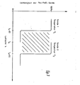
- Fig. 3 zeigt die Möglichkeit, mit Hilfe zweier Sonden die Luftzahl λ auf einem Wert λo ± Δλ zu stabilisieren. Die Temperatur T1 der ersten Sonde ist so eingestellt, dass die Sauerstoffabgabe bei einem Wert λo-Δλ erfolgt, während die Temperatur T2 der Sonde 2 so eingestellt ist, dass die Sauerstoffabgabe bei einer Luftzahl λo+Δλ erfolgt. Auf diese Weise ist der Bereich λo ± Δλ eindeutig durch den Zustand der beiden Sonden definiert. Im Regelbereich (schraffiert) ist die erste Sonde oxidiert und die zweite Sonde reduziert. Ausserhalb des Regelbereichs sind entweder beide Sonden oxidiert oder reduziert.
Claims (6)
Priority Applications (1)
| Application Number | Priority Date | Filing Date | Title |
|---|---|---|---|
| AT80100844T ATE1960T1 (de) | 1979-04-21 | 1980-02-21 | Sauerstoffmesssonde. |
Applications Claiming Priority (2)
| Application Number | Priority Date | Filing Date | Title |
|---|---|---|---|
| DE2916178 | 1979-04-21 | ||
| DE2916178A DE2916178C2 (de) | 1979-04-21 | 1979-04-21 | Sonde zur Messung des Sauerstoffpartialdrucks in Gasen |
Publications (3)
| Publication Number | Publication Date |
|---|---|
| EP0017729A2 true EP0017729A2 (de) | 1980-10-29 |
| EP0017729A3 EP0017729A3 (en) | 1980-11-26 |
| EP0017729B1 EP0017729B1 (de) | 1982-12-08 |
Family
ID=6068907
Family Applications (1)
| Application Number | Title | Priority Date | Filing Date |
|---|---|---|---|
| EP80100844A Expired EP0017729B1 (de) | 1979-04-21 | 1980-02-21 | Sauerstoffmesssonde |
Country Status (5)
| Country | Link |
|---|---|
| US (1) | US4351182A (de) |
| EP (1) | EP0017729B1 (de) |
| JP (1) | JPS55147344A (de) |
| AT (1) | ATE1960T1 (de) |
| DE (1) | DE2916178C2 (de) |
Cited By (1)
| Publication number | Priority date | Publication date | Assignee | Title |
|---|---|---|---|---|
| GB2149120A (en) * | 1983-10-31 | 1985-06-05 | Atomic Energy Authority Uk | Improvements in or relating to sensors |
Families Citing this family (27)
| Publication number | Priority date | Publication date | Assignee | Title |
|---|---|---|---|---|
| JPS58191962A (ja) * | 1982-05-07 | 1983-11-09 | Hitachi Ltd | ガス検出素子 |
| JPS5927253A (ja) * | 1982-08-06 | 1984-02-13 | Shinei Kk | ガスセンサおよびその製造法 |
| JPS5991350A (ja) * | 1982-11-17 | 1984-05-26 | Toyota Central Res & Dev Lab Inc | 薄膜酸素センサ |
| DE3321165C1 (de) * | 1983-06-11 | 1984-08-02 | Du Pont de Nemours (Deutschland) GmbH, 4000 Düsseldorf | Verfahren zur kontinuierlichen Vorausbestimmung und Überwachung des Sauerstoffbedarfs bei der Verbrennung schwefelwasserstoffhaltiger Gasgemische zur Schwefelgewinnung und Abgasreinigung |
| US4591423A (en) * | 1984-03-16 | 1986-05-27 | Ngk Insulators, Ltd. | Oxygen sensor |
| US4587105A (en) * | 1984-05-17 | 1986-05-06 | Honeywell Inc. | Integratable oxygen sensor |
| DE3722608A1 (de) * | 1987-07-09 | 1989-02-02 | Gyulai Maria Dobosne | Anordnung und verfahren zur erfassung und anzeige der konzentrationen von zigaretten-, zigarren-, pfeifen- und autoabgasrauch |
| US5324415A (en) * | 1989-06-09 | 1994-06-28 | Blumenthal Robert N | Apparatus and systems for analyzing a sample of treatment atmosphere having a carbon potential |
| US4966348A (en) * | 1989-06-30 | 1990-10-30 | Lindberg Corp. | Method and apparatus for monitoring atmosphere in furnaces |
| DE4042557C2 (de) * | 1990-12-06 | 1996-11-28 | Lehmann Martin | Verfahren zur Analyse von Gasproben und Analyseanordnung |
| IT1273044B (it) * | 1994-07-19 | 1997-07-01 | Weber Srl | Sistema elettronico di controllo titolo della miscela aria benzina alimentata ad un motore a combustione interna |
| IT1273045B (it) * | 1994-07-19 | 1997-07-01 | Weber Srl | Sistema elettronico di controllo titolo della miscela aria benzina alimentante un motore a combustione interna. |
| US5698771A (en) * | 1995-03-30 | 1997-12-16 | The United States Of America As Represented By The United States National Aeronautics And Space Administration | Varying potential silicon carbide gas sensor |
| DE19549090C2 (de) * | 1995-11-08 | 1997-09-25 | Honda Motor Co Ltd | NOx-Sensor für Abgas |
| DE19542038A1 (de) * | 1995-11-10 | 1997-05-15 | Roth Technik Gmbh | Katalysator |
| JPH11118745A (ja) * | 1997-08-04 | 1999-04-30 | Ford Global Technol Inc | 比例制御用の相転移に基づく高感度酸素センサー及びそれを用いた酸素分圧変化の検出方法 |
| US5798269A (en) * | 1997-08-04 | 1998-08-25 | Ford Global Technologies, Inc. | Method for detecting change in oxygen partial pressure based on metal/metal oxide phase transformations |
| US5783153A (en) * | 1997-08-04 | 1998-07-21 | Ford Global Technologies, Inc. | Metal oxide oxygen sensors based on phase transformation |
| US5876673A (en) * | 1997-08-04 | 1999-03-02 | Ford Global Technologies, Inc. | High sensitivity phase transformation-based oxygen sensors for proportional control |
| DE69804174T2 (de) * | 1997-08-04 | 2002-10-02 | Ford Global Technologies, Inc. | Metalloxidsauerstoffsensoren auf der Basis eines Phasenübergangs |
| US5942674A (en) * | 1997-08-04 | 1999-08-24 | Ford Global Technologies, Inc. | Method for detecting oxygen partial pressure using a phase-transformation sensor |
| AU2003900184A0 (en) * | 2003-01-16 | 2003-01-30 | Ceramic Fuel Cells Limited | Method of operating a fuel cell |
| AU2004204518B2 (en) * | 2003-01-16 | 2010-02-04 | Ceramic Fuel Cells Limited | Method of operating a fuel cell |
| JP4341651B2 (ja) * | 2006-07-28 | 2009-10-07 | 株式会社日立製作所 | 熱式ガス流量計 |
| WO2016096022A1 (en) * | 2014-12-18 | 2016-06-23 | Honeywell International Inc. | Sensing oxygen |
| JP7195766B2 (ja) * | 2018-05-14 | 2022-12-26 | キヤノン株式会社 | 還元性ガス検知材料、及び還元性ガス検知センサ |
| US11686698B2 (en) | 2018-05-14 | 2023-06-27 | Canon Kabushiki Kaisha | Reducing gas detection material and reducing gas detection sensor |
Family Cites Families (9)
| Publication number | Priority date | Publication date | Assignee | Title |
|---|---|---|---|---|
| US2207868A (en) * | 1938-01-25 | 1940-07-16 | Hercules Powder Co Ltd | Hydrogenation catalyst and method of preparing the same |
| US3340014A (en) * | 1964-07-31 | 1967-09-05 | Gen Electric | Stoichiometric indicator for combustion of gas |
| US3426579A (en) * | 1965-09-03 | 1969-02-11 | Boeing Co | Continuous monitor for the rapid detection of hydrogen and oxygen |
| US3567383A (en) * | 1968-10-01 | 1971-03-02 | Engelhard Min & Chem | Hydrogen detectors |
| US3865550A (en) * | 1970-08-26 | 1975-02-11 | Nat Res Dev | Semi-conducting gas sensitive devices |
| US4001758A (en) * | 1975-09-02 | 1977-01-04 | Ford Motor Company | Stoichiometric air/fuel ratio exhaust gas sensor |
| JPS5315886A (en) * | 1976-07-28 | 1978-02-14 | Nippon Denso Co Ltd | Oxygen concentration detector |
| GB1595421A (en) * | 1977-04-12 | 1981-08-12 | Lucas Industries Ltd | Device for minitoring the composition of the exhaust emission of a combustion process |
| US4125374A (en) * | 1977-11-21 | 1978-11-14 | Bendix Autolite Corporation | Method and apparatus for determining combustion mixture air/fuel ratio |
-
1979
- 1979-04-21 DE DE2916178A patent/DE2916178C2/de not_active Expired
-
1980
- 1980-02-21 AT AT80100844T patent/ATE1960T1/de not_active IP Right Cessation
- 1980-02-21 EP EP80100844A patent/EP0017729B1/de not_active Expired
- 1980-03-17 JP JP3383380A patent/JPS55147344A/ja active Pending
- 1980-03-26 US US06/134,123 patent/US4351182A/en not_active Expired - Lifetime
Cited By (1)
| Publication number | Priority date | Publication date | Assignee | Title |
|---|---|---|---|---|
| GB2149120A (en) * | 1983-10-31 | 1985-06-05 | Atomic Energy Authority Uk | Improvements in or relating to sensors |
Also Published As
| Publication number | Publication date |
|---|---|
| DE2916178A1 (de) | 1980-10-23 |
| JPS55147344A (en) | 1980-11-17 |
| DE2916178C2 (de) | 1982-04-22 |
| US4351182A (en) | 1982-09-28 |
| EP0017729A3 (en) | 1980-11-26 |
| ATE1960T1 (de) | 1982-12-15 |
| EP0017729B1 (de) | 1982-12-08 |
Similar Documents
| Publication | Publication Date | Title |
|---|---|---|
| DE2916178C2 (de) | Sonde zur Messung des Sauerstoffpartialdrucks in Gasen | |
| DE2517798C2 (de) | Vorrichtung zur Steuerung eines mageren Verbrennungsgemisches für eine Brennkraftmaschine von Kraftfahzeugen | |
| DE3782584T2 (de) | Elektrochemischer nox-sensor. | |
| DE2608487C3 (de) | Gasdetektor | |
| DE69535008T2 (de) | Messverfahren zur Bestimmung der NOx Konzentration in einem Gas | |
| DE2341422A1 (de) | Messgeraet | |
| DE4333232B4 (de) | Meßfühler zur Bestimmung des Sauerstoffgehaltes von Gasgemischen | |
| DE2233299A1 (de) | Anordnung zur abgasregulierung in verbrennungsmaschinen | |
| DE3028274A1 (de) | Vorrichtung zum erzeugen eines regelsignales fuer die rueckkopplungsregelung des kraftstoff-luftverhaeltnisses eines einer verbrennungseinrichtung gelieferten kraftstoff-luftgemisches | |
| DE3019072A1 (de) | Vorrichtung zur bestimmung der sauerstoffkonzentration in verbrennungsgasen | |
| DE2246625B2 (de) | Kraftstoffzumeßanlage | |
| DE4341632C2 (de) | Verfahren und Einrichtung zur Prüfung und Regelung von Kraftfahrzeugen | |
| DE3006525A1 (de) | Verfahren und geraet zum messen des brennstoff-/luftverhaeltnisses eines gemisches, das einem verbrennungssystem zugefuehrt wird | |
| DE4221922C1 (de) | Wärmetönungssensor | |
| DE3445755A1 (de) | Luft/kraftstoffverhaeltnis-detektor | |
| DE3445754A1 (de) | Verfahren zur messung des luft/kraftstoffverhaeltnisses in einem abgas und luft/kraftstoffverhaeltnis-detektor dafuer | |
| DE2247656B2 (de) | Einrichtung zum Regeln des Verhältnisses der Kraftstoff- und Luftanteile des Betriebsgemisches einer Brennkraftmaschine | |
| DE3120159A1 (de) | Elektrochemischer messfuehler fuer die bestimmung des sauerstoffgehaltes in gasen | |
| DE102010063529A1 (de) | Heizelement | |
| DE2329539C3 (de) | Verfahren zum Entgiften der Abgase | |
| DE2738755C3 (de) | Elektrochemische Meßzelle | |
| DE4391637C2 (de) | Sensor für das Luft-/Brennstoff-Verhältnis einer Verbrennungskraftmaschine | |
| DE3928860A1 (de) | Verfahren und vorrichtung zur verbesserung des abgasverhaltens von gemischverdichtenden brennkraftmaschinen | |
| DE69228507T2 (de) | Sauerstoffsensor | |
| DE4210398C2 (de) | Anordnung zur Bestimmung eines Gaspartialdruckes in einem Gasgemisch |
Legal Events
| Date | Code | Title | Description |
|---|---|---|---|
| PUAI | Public reference made under article 153(3) epc to a published international application that has entered the european phase |
Free format text: ORIGINAL CODE: 0009012 |
|
| PUAL | Search report despatched |
Free format text: ORIGINAL CODE: 0009013 |
|
| AK | Designated contracting states |
Designated state(s): AT BE CH FR GB IT NL SE |
|
| AK | Designated contracting states |
Designated state(s): AT BE CH FR GB IT NL SE |
|
| 17P | Request for examination filed |
Effective date: 19801024 |
|
| ITF | It: translation for a ep patent filed | ||
| GRAA | (expected) grant |
Free format text: ORIGINAL CODE: 0009210 |
|
| AK | Designated contracting states |
Designated state(s): AT BE CH FR GB IT NL SE |
|
| REF | Corresponds to: |
Ref document number: 1960 Country of ref document: AT Date of ref document: 19821215 Kind code of ref document: T |
|
| ET | Fr: translation filed | ||
| ITTA | It: last paid annual fee | ||
| PGFP | Annual fee paid to national office [announced via postgrant information from national office to epo] |
Ref country code: NL Payment date: 19890228 Year of fee payment: 10 |
|
| PGFP | Annual fee paid to national office [announced via postgrant information from national office to epo] |
Ref country code: CH Payment date: 19890413 Year of fee payment: 10 |
|
| PGFP | Annual fee paid to national office [announced via postgrant information from national office to epo] |
Ref country code: SE Payment date: 19890420 Year of fee payment: 10 |
|
| PGFP | Annual fee paid to national office [announced via postgrant information from national office to epo] |
Ref country code: AT Payment date: 19890421 Year of fee payment: 10 |
|
| PGFP | Annual fee paid to national office [announced via postgrant information from national office to epo] |
Ref country code: FR Payment date: 19890426 Year of fee payment: 10 |
|
| PGFP | Annual fee paid to national office [announced via postgrant information from national office to epo] |
Ref country code: GB Payment date: 19890430 Year of fee payment: 10 |
|
| PGFP | Annual fee paid to national office [announced via postgrant information from national office to epo] |
Ref country code: BE Payment date: 19890512 Year of fee payment: 10 |
|
| PG25 | Lapsed in a contracting state [announced via postgrant information from national office to epo] |
Ref country code: GB Effective date: 19900221 Ref country code: AT Effective date: 19900221 |
|
| PG25 | Lapsed in a contracting state [announced via postgrant information from national office to epo] |
Ref country code: SE Effective date: 19900222 |
|
| PG25 | Lapsed in a contracting state [announced via postgrant information from national office to epo] |
Ref country code: CH Effective date: 19900228 Ref country code: BE Effective date: 19900228 |
|
| REG | Reference to a national code |
Ref country code: GB Ref legal event code: 732 |
|
| BERE | Be: lapsed |
Owner name: DORNIER SYSTEM G.M.B.H. Effective date: 19900228 |
|
| PG25 | Lapsed in a contracting state [announced via postgrant information from national office to epo] |
Ref country code: NL Effective date: 19900901 |
|
| NLV4 | Nl: lapsed or anulled due to non-payment of the annual fee | ||
| GBPC | Gb: european patent ceased through non-payment of renewal fee | ||
| PG25 | Lapsed in a contracting state [announced via postgrant information from national office to epo] |
Ref country code: FR Effective date: 19901031 |
|
| REG | Reference to a national code |
Ref country code: CH Ref legal event code: PL |
|
| REG | Reference to a national code |
Ref country code: FR Ref legal event code: ST |
|
| EUG | Se: european patent has lapsed |
Ref document number: 80100844.2 Effective date: 19901107 |
|
| PLBE | No opposition filed within time limit |
Free format text: ORIGINAL CODE: 0009261 |
|
| STAA | Information on the status of an ep patent application or granted ep patent |
Free format text: STATUS: NO OPPOSITION FILED WITHIN TIME LIMIT |