EP0017780A1 - Vorrichtung zum Entfernen von Lanzenbären - Google Patents
Vorrichtung zum Entfernen von Lanzenbären Download PDFInfo
- Publication number
- EP0017780A1 EP0017780A1 EP80101437A EP80101437A EP0017780A1 EP 0017780 A1 EP0017780 A1 EP 0017780A1 EP 80101437 A EP80101437 A EP 80101437A EP 80101437 A EP80101437 A EP 80101437A EP 0017780 A1 EP0017780 A1 EP 0017780A1
- Authority
- EP
- European Patent Office
- Prior art keywords
- lance
- arm
- jaw
- jaw arm
- scraper blade
- Prior art date
- Legal status (The legal status is an assumption and is not a legal conclusion. Google has not performed a legal analysis and makes no representation as to the accuracy of the status listed.)
- Granted
Links
- 210000003625 skull Anatomy 0.000 title claims abstract description 42
- 230000003213 activating effect Effects 0.000 claims abstract description 13
- 239000012530 fluid Substances 0.000 claims description 9
- 230000006835 compression Effects 0.000 claims description 7
- 238000007906 compression Methods 0.000 claims description 7
- QVGXLLKOCUKJST-UHFFFAOYSA-N atomic oxygen Chemical compound [O] QVGXLLKOCUKJST-UHFFFAOYSA-N 0.000 description 12
- 239000001301 oxygen Substances 0.000 description 12
- 229910052760 oxygen Inorganic materials 0.000 description 12
- 238000000034 method Methods 0.000 description 7
- 238000007664 blowing Methods 0.000 description 6
- 238000012360 testing method Methods 0.000 description 6
- 238000007790 scraping Methods 0.000 description 5
- 239000002893 slag Substances 0.000 description 5
- XEEYBQQBJWHFJM-UHFFFAOYSA-N Iron Chemical compound [Fe] XEEYBQQBJWHFJM-UHFFFAOYSA-N 0.000 description 4
- 239000002184 metal Substances 0.000 description 4
- 229910052751 metal Inorganic materials 0.000 description 4
- XLYOFNOQVPJJNP-UHFFFAOYSA-N water Substances O XLYOFNOQVPJJNP-UHFFFAOYSA-N 0.000 description 4
- 229910000831 Steel Inorganic materials 0.000 description 3
- 238000004140 cleaning Methods 0.000 description 3
- 239000007789 gas Substances 0.000 description 3
- 239000000463 material Substances 0.000 description 3
- 239000012768 molten material Substances 0.000 description 3
- 230000008569 process Effects 0.000 description 3
- 239000007921 spray Substances 0.000 description 3
- 239000010959 steel Substances 0.000 description 3
- 239000011248 coating agent Substances 0.000 description 2
- 238000000576 coating method Methods 0.000 description 2
- 229910052742 iron Inorganic materials 0.000 description 2
- 230000007246 mechanism Effects 0.000 description 2
- 239000000155 melt Substances 0.000 description 2
- 238000012986 modification Methods 0.000 description 2
- 230000004048 modification Effects 0.000 description 2
- 238000009825 accumulation Methods 0.000 description 1
- 239000008186 active pharmaceutical agent Substances 0.000 description 1
- 238000012863 analytical testing Methods 0.000 description 1
- 230000015572 biosynthetic process Effects 0.000 description 1
- 230000008878 coupling Effects 0.000 description 1
- 238000010168 coupling process Methods 0.000 description 1
- 238000005859 coupling reaction Methods 0.000 description 1
- 238000005520 cutting process Methods 0.000 description 1
- 230000003116 impacting effect Effects 0.000 description 1
- 238000002347 injection Methods 0.000 description 1
- 239000007924 injection Substances 0.000 description 1
- 238000005461 lubrication Methods 0.000 description 1
- 238000004519 manufacturing process Methods 0.000 description 1
- 230000013011 mating Effects 0.000 description 1
- 239000002923 metal particle Substances 0.000 description 1
- 239000000203 mixture Substances 0.000 description 1
- 239000013618 particulate matter Substances 0.000 description 1
- 230000037361 pathway Effects 0.000 description 1
- 230000003014 reinforcing effect Effects 0.000 description 1
- 230000003252 repetitive effect Effects 0.000 description 1
- 230000000717 retained effect Effects 0.000 description 1
- 238000005201 scrubbing Methods 0.000 description 1
Images



Classifications
-
- C—CHEMISTRY; METALLURGY
- C21—METALLURGY OF IRON
- C21C—PROCESSING OF PIG-IRON, e.g. REFINING, MANUFACTURE OF WROUGHT-IRON OR STEEL; TREATMENT IN MOLTEN STATE OF FERROUS ALLOYS
- C21C5/00—Manufacture of carbon-steel, e.g. plain mild steel, medium carbon steel or cast steel or stainless steel
- C21C5/28—Manufacture of steel in the converter
- C21C5/42—Constructional features of converters
- C21C5/46—Details or accessories
- C21C5/4606—Lances or injectors
- C21C5/462—Means for handling, e.g. adjusting, changing, coupling
Definitions
- This invention relates to apparatus for a basic oxygen furnace and, more particularly, to apparatus for removing skull from metallurgical lances associated with metallurgical furnaces, such as basic oxygen furnaces.
- an overhead water-cooled lance is used to force purified oxygen under high pressure against the surface of the molten metal in a refractory lined, closed bottom converter. While the oxygen lance is inserted within the converter, a sensor lance may also be lowered into and retracted from the converter during the operation to test the melt.
- these metallurgical lances extend through the hood of a vent or duct system which covers the mouth of the converter to collect for cleaning and scrubbing the hot gases which are generated during the blowing process.
- the oxygen impacts the surface of the molten metal which is covered by a layer of slag such that the slag and other molten materials are splashed about within the converter.
- Some of this molten material contacts the relatively cool outer surface of the metallurgical lances and solidifies there forming what is commonly called a skull. If not removed, the solidified material can quickly accumulate on the lances to the point where the added weight and the increased dimension of the skull- containing lance interfere with efficient operation. The coating may become so thick that the lance cannot be withdrawn from the opening in the hood or so heavy the hoisting means cannot lift the lance.
- the skulls are not removed from sensor lances after each test, they interfere with the injection of test devices in subsequent tests. This leads to operating downtime to remove the skulls by prying with a bar or cutting with a torch.
- U.S. 3,912,244 that comprises a scraping means to contact and scrape the outer surface of the lance as it is raised from the converter to automatically remove adhered material.
- an oxygen lance is disclosed that has a water spray system incorporated into the structure of the lance including exit water spray nozzles in the wall of the lance barrel for emitting a water spray from the water jacket around the barrel to prevent skull formation.
- Another method and apparatus for removing encrustations from a metallurgical lance is disclosed in U.S. 4,052,044.
- a tool is displaced relative to the lance and in contact with the layer of encrustation on the lance.
- a repetitive movement is applied to the tool against the layer to dislodge it.
- the deskulling apparatus can be mounted on a supporting member positioned relative to the lance and metallurgical furnace.
- the invention is a metallurgical lance deskulling apparatus comprising opposed scraper blades adapted for movement toward and away from a metallurgical lance and guide rollers operatively connected to the scraper blades and arranged to contact the surface of the lance while maintaining the scraper blades a predetermined distance from the surface of the lance which is less than the thickness of skull deposits on the lance.
- the apparatus comprises a main arm to which two jaw arms are pivotally attached.
- positioning means which may be a fluid actuator attached to positioning arms, are mounted on the supporting member and the main arm is fixed to the positioning means.
- Activating means are secured to the main arm to provide movement to each jaw arm relative to the main arm.
- a guide roller is rotatably mounted on each jaw arm.
- a scraper blade is fastened to each jaw arm in a spaced relationship with the roller such that the scraper blade is disposed apart from the lance when the guide roller contacts the lance.
- the scraper blade is yieldably fastened to the jaw arm for movement upward and away from the lance when a skull cannot be dislodged from a retracting lance by the scraper blades.
- the deskulling device is preferably attached by positioning means to a supporting means comprising a box having spring-loaded doors for enclosing the retracted device when not in use.
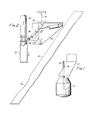
- a refractory-lined converter 11 is charged with molten iron, scrap steel and slag-forming materials.
- a vent system comprising a hood 12 and associated duct-work is positioned over the mouth of the converter 11 to capture evolved gases and entrained particulates for conveyance to gas cleaning apparatus not shown.
- a metallurgical lance 14 is inserted into converter 11 through an opening 16 in hood 12.
- Lance 14 can be the conduit through which purified oxygen is injected into the converter 11 to impinge the molten metal after blowing a pathway through the layer of slag.
- Lance 14 could also be a sensor lance that is introduced into the melt for analytical testing purposes.
- the deskuller apparatus 18 shown generally in Figure 2 can be constructed and adapted to strip the metal and slag skull 20 from either an oxygen lance or a sensor lance depicted generally in the drawings as metallurgical lance 14. It is to be understood that lance 14 can be either of such lances.
- Deskuller 18 basically comprises main arm 22 and two jaw arms 24 and preferably also has positioning means identified generally as 26.
- Deskuller 18 is housed in deskuller box 28 having a pair of doors 30 for enclosing the retracted apparatus to prevent accumulation of furnace slag, dirt and metal particles in the mechanism.
- the deskuller 18 and the box 28 are secured to supporting member 32.
- the ability to extend and retract the main arm 22 and the jaw arms 24 into the box 28 using positioning means 26 allows the apparatus to be disposed at a distance relative to the lance 14 so that the lance feeder and hoses, not shown, can pass by without interference on the downward travel of lance 14.
- positioning means 26 comprises fluid actuator 34 together with linking arm 36 and linking arm 38 which are the positioning arms.
- Fluid actuator 34 'which may be pneumatically or hydraulically actuated, is hinged at one end by bracket 40 to deskuller box 28 which is in turn secured to supporting member 32.
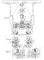
- Fluid actuator 34 has actuator rod 42 pivotally secured between parallel members 44 (see Figure 3) composing linking arm 36 at a point intermediate the ends of members 44.
- One end of parallel members 44 is swingably attached to the inside of the deskuller box 28 by coupling 46 while the opposite ends are pivotally secured to either side of one end of linking arm 38 to permit movement about the point of attachment. This movement is restricted by self-locking linkage 48 connecting parallel members 44 of linking arm 36.
- the other end of linking arm 38 is fastened by yoke 50 in a hinged manner to the top of main arm 22.
- main arm 22 Extending at a downward angle from either side of one end and composing part of main arm 22 are two legs 52 which are pivotally attached to the bottom of deskuller box 28 via brackets 54 and fastening rod 56. Reinforcing plates connecting the legs may be added to strengthen the structure.
- the opposite end of main arm 22 bifurcates into horizontal upper and lower holding members 58 and 60 ( see Figure 4). With reference to Figures 4 and 5 a supporting top plate 62 is secured to the top side of upper holding member 58.
- Forked jaw arms 24, which have prongs 64 and 66 see Figure 5 are sandwiched between holding members 58 and 60.
- a supporting bottom plate,not shown, comparable to top plate 62 may be attached to the underside of lower holding member 60.
- pins 68 pass through the concentrically aligned openings in top plate 62, holding members 58 and 60, and jaw arms 24 to fasten these elements together, jaw arms 24 are never - theless individually capable of pivotal movement about pins 68.
- Pivotally held by pin 70 in the slot between prongs 64 and-66 of each jaw arm 24 is a rod 72 which, as shown in Figure 3, extends from an activating means 74 the opposite end of which is clamped by brackets 76 to the side of main arm 22.
- Activating means 74 may comprise pneumatic or hydraulic compression cylinders.
- Pins 68 and 70 preferably have borings and are adapted via these borings to permit lubrication of the elements that pivot about these pins..
- an L-shaped jaw arm framecomprising frame plates 78 and 80 is welded to each jaw arm 24 and prongs 64 and 66.
- Located on the under - side of jaw arm frame plate 80 are two spaced hinge barrels 82 having bores in alignment to receive rod 84.
- Blade holder 86 comprises cylindrical section 88, upright flange 90 and bracers 92. When the cylindrical section 88 is disposed between the hinge barrels 82, the bore of cylindrical section 88 is coaxial with those of hinge barrels 82 so that the blade holder 86 can swivel about inserted rod 84.
- Scraper blade 94 is detachably bolted to the underside of blade holder 86 by bolts 93 which pass into bracers 92.
- the blade 94 has arcuate inner edge 96 which should preferably have a slightly larger radius of curvature than the lance.
- a stop 98 is welded to a hinge barrel 82 of jaw arm frame plate 80 to restrict the movement of blade holder 86 about rod 84 by contacting the underside of scraper blade 94 and holding it in a position substantially perpendicular to jaw arm frame plate 80.
- compression spring 102 Passing through an inclined hole 100 in jaw arm frame plate 80 is compression spring 102 which at one end internally receives rod 104 welded to a notch in flange 90 of blade holder 86. A washer is disposed about rod 104 between spring lo2 and upright flange 90.
- Rod 106 is welded to cover 108 which is bolted to jaw arm frame plate 80 so that rod 106 inserts within the coils of spring 102 whereby the spring biases between the blade holder 86 and jaw arm frame plate 80 via cover 108.
- the means for bolting cover 108 to jaw arm frame plate 80 are adapted to permit the compression of spring 102 to be adjusted by turning bolts 110.
- the compression of spring 102 serves to yieldably bias the scraper blade holder 86 in a position such that the scraper blade 94 is approximately horizontal and extending towards the lance. Any other suitable biasing means known to an ordinary skilled worker can be used for yieldably mounting the scraper blade holder 86.
- keepers 112 Fixed to the top of frame plate 80 are keepers 112 which rotatably support guide roller 114 on axial rod 116.
- the keepers 112 and guide roller 114 are positioned on the jaw arm frame plate 80 such that when the roller 114 contacts the lance 14 the inner arcuate edge 96 of scraper blade 94 is disposed in close, but non-contacting proximity to the surface of the lance 14.
- fluid actuator 34 is activated to advance actuator rod 42 causing linking arm 36 and linking arm 38 to extend into alignment.
- main arm 22 pivots outwardly from deskuller box 28 to place jaw arms 24 in a transverse position across the lance 14.
- activating means 74 propel rods 72 forward moving jaw arms 24 toward lance 14 until guide rollers 114 contact the sides of the lance 14 and are forceably held in place while still allowing longitudinal movement of the lance between the rollers.
- the jaw arms close around the lance to form a substan - tially circular scraping edge.
- Scraper blades 94 are now positioned so that the arcuate blade edge 96 is disposed slightly away from the lance surface, preferably with a 1/32 to 1/16 inch (.079 to 0.159 cm) set back or space between the edge 96 of the blade and the surface of the lance 14. As the lance is withdrawn, this spacing of the scraper blade 94 from the lance prevents digging and gouging of the surface of the lance. As the lance retracts, it moves smoothly between the guide rollers 114 with the skull 20 on the end of the lance eventually impacting the scraper blades 94. Continued upward movement of the lance disengages the skull 20 which slips downward from the end of the lance and into the converter 11.
- jaw arms should be closed about a clean surface of the lance before the blades impact the skull. Otherwise, the guide rollers will contact and ride on the skull. In such a situation the scraper blades can only remove the skull if the blades make contact with any of the numerous bumps and projections on the skull surface.
- the scraping blades 94 are preferably detachably bolted to blade holder 86.
- the scraping blades may alternatively be directly secured to the jaw arm frame in a non-biased manner, again with the proviso that the scraper blades are positioned relative to the rollers so that the blade edge is somewhat set back from the surface of the lance.
- the scraper blade edge is arcuate in order to present a substantially mating configuration with the lance without actual contact between the two.
- the scraper blade may be machined to possess a scraping edge of any configuration desired, such as those variations shown in Figure 7 by way of example.
- the scraper blades are preferably.yieldably mounted for upward pivotal movement as set forth in the above- detailed description of the spring-loaded embodiment. Any biasing means of attachment between the scraper blade and the jaw arm are contemplated to be within the' scope of this invention. This particular feature of the apparatus offers a considerable degree of safety.
- the scraper blades can pivot upwardly, as shown by the dotted lines in Figure 6, to permit a skull which is "cemented" onto the lance to pass upwardly through the jaw arms.
- the spring force is ad - justable to provide a safety margin for the particular hoist system.
- the skull will be imparting to the scraper blades and blade holders an angular force consisting of a vertical and a horizontal component. The horizontal component of the angular force will overcome the countering force applied by the jaw arm activating means causing the jaw arms to part into the open position. Consequently, the skull containing lance can readily pass through.
- the compression springs which are adjustable over a range of tension are usually set to impart 500-1000 lb ( 226,5 - 453,o kp) downward force to each scraper blade and the pneumatic cylinders of activating means 74 are each supplied with 40 - 100 lb/in 2 (2,8 - 7,0 kp/cm 2 ) air pressure.
- the pneumatic cylinders of activating means 74 are each supplied with 40 - 100 lb/in 2 (2,8 - 7,0 kp/cm 2 ) air pressure.
- the preferred embodiment as revealed in Figures 3-6 was pneumatically powered.
- An electro-pneumatic timing circuit was adapted to automatically operate the device for removing skulls from a sensor lance which, in its retracted position, can be moved transversely away from the converter.
- the control scheme contains interlock switches to prevent movement of the lance in any direction other than up when the deskuller is in use.
- the pneumatic control scheme and the electrical control scheme are presented in Figures 9 and 10 respectively.
- the sensor lance 14 is lowered into the metallurgical furnace 11 for a test, a total travel of about 650 in. (1651 cm).
- the lance is started upward after the test.
- an electrical signal is received from the hoisting apparatus and activates relay CR2 in the deskuller control system.
- the skull on the lance is usually located in the last 200 in. (508 cm) of the hoisting distance, or equivalently the bottom 200 in. (508 cm) of the length of the lance.
- Cam electrical-switch TS-5 opens and deactivates relay DS which opens remote electrical contacts in the lance traverse circuit so that, as a safety feature, the lance cannot be traversed away for 25 seconds.
- Cam electrical-switch TS-1 activates an electrical air-valve SV-1 to extend the main arm cylinder (fluid actuator 34). This movement of the apparatus out of the box triggers an air valve V-1 which opens pressure switch PS-1 to remove the ability to traverse the lance.
- Cam electrical-switch TS-2 activates an electrical air-valve SV-4 to extend the jaw arm cylinders (activating means 74) thereby closing the jaw arms 24 so that the guide rollers contact the lance. Deskulling can now proceed as the lance is further retracted.
- cam electrical-switch TS-3 activates electrical air-valve SV-3 to retract the jaw arm cylinders ( activating means 74) to open the jaw arms 24.
- Cam electrical-switch TS-4 activates electrical air-valve SV-2 to retract the main arm cylinder (fluid actuator 34) pulling the apparatus back into the housing box.
- the pressure valve V-1 resets pressure switch PS-1 for permission to traverse.
- Cam electrical-switch TS-5 closes and reinstates the sensor lance traverse circuit and the lance 14 is traversed away.
- Figure 8 depicting apparatus comprising opposed scraper blades which are adapted for movement toward and away from the metallurgical lance and guide rollers operatively connected to the scraper blades.
- the guide rollers are spatially arranged to contact the surface of the lance while keeping the scraper blades a predetermined distance from the surface of the lance. This distance is less than the thickness of the skull deposited on the lance.
- the deskulling apparatus of Figure 8 has two substantially opposed arms 120 each having a guide roller 122 which is rotatably mounted.
- a scraper blade 124 is fixed to each arm 120 in a spaced relationship with the guide roller 122 so that the scraper blade 124 is slightly set back a predetermined distance from the lance 14 when the guide roller 122 contacts the lance.
- Attached to the arms 120 are means 126 for imparting coacting individual movement to the arms 120 in order.to move the scraper blades 124 to a position transversely surrounding the lance 14 with the rollers 122 contacting the lance.
- the scraper blades are yieldably mounted in the embodiment of Figure 8 in the following manner.
- Arm 120 on which guide roller 122 is rotatably mounted, has its upper end 128 pivotally secured to support member 130 and its lower end 132 pivotally secured by holder 134 to scraper blade 124 which has an extended portion 136 opposite the end that contacts the skull.
- Means 126 which may be pneumatic cylinders, are attached between each arm 120 and its associated support member 130 for moving the cooperatively connected guide rollers 122 and scraper blades 124 into a position transversely surrounding the lance with the guide rollers 122 contacting the lance while the scraper blades 124 are set back a predetermined distance .
- Fastened to the extended portion 136 of the scraper blade is one end of rod 138 which is inserted through a hole 140 in support member 130, spring keeper 142 which rests on the bottom of support member 130 and coiled spring 144 which is retained in position by fastener 146.
- spring keeper 142 which rests on the bottom of support member 130
- coiled spring 144 which is retained in position by fastener 146.
Landscapes
- Engineering & Computer Science (AREA)
- Chemical & Material Sciences (AREA)
- Manufacturing & Machinery (AREA)
- Materials Engineering (AREA)
- Metallurgy (AREA)
- Organic Chemistry (AREA)
- Carbon Steel Or Casting Steel Manufacturing (AREA)
- Refinement Of Pig-Iron, Manufacture Of Cast Iron, And Steel Manufacture Other Than In Revolving Furnaces (AREA)
- Treatment Of Steel In Its Molten State (AREA)
Priority Applications (1)
| Application Number | Priority Date | Filing Date | Title |
|---|---|---|---|
| AT80101437T ATE6672T1 (de) | 1979-03-26 | 1980-03-19 | Vorrichtung zum entfernen von lanzenbaeren. |
Applications Claiming Priority (2)
| Application Number | Priority Date | Filing Date | Title |
|---|---|---|---|
| US06/024,282 US4226407A (en) | 1979-03-26 | 1979-03-26 | Metallurgical lance deskuller |
| US24282 | 1979-03-26 |
Publications (2)
| Publication Number | Publication Date |
|---|---|
| EP0017780A1 true EP0017780A1 (de) | 1980-10-29 |
| EP0017780B1 EP0017780B1 (de) | 1984-03-14 |
Family
ID=21819791
Family Applications (1)
| Application Number | Title | Priority Date | Filing Date |
|---|---|---|---|
| EP80101437A Expired EP0017780B1 (de) | 1979-03-26 | 1980-03-19 | Vorrichtung zum Entfernen von Lanzenbären |
Country Status (4)
| Country | Link |
|---|---|
| US (1) | US4226407A (de) |
| EP (1) | EP0017780B1 (de) |
| AT (1) | ATE6672T1 (de) |
| DE (1) | DE3066907D1 (de) |
Cited By (1)
| Publication number | Priority date | Publication date | Assignee | Title |
|---|---|---|---|---|
| EP0164331A3 (en) * | 1984-05-08 | 1986-04-02 | Voest-Alpine Aktiengesellschaft | Arrangement for cleaning the lance head of a lance introducible into a metallurgical vessel |
Families Citing this family (7)
| Publication number | Priority date | Publication date | Assignee | Title |
|---|---|---|---|---|
| DE3106234A1 (de) * | 1981-02-20 | 1982-09-02 | Fried. Krupp Gmbh, 4300 Essen | "verfahren und vorrichtung zur beseitigung von ansaetzen an bezueglich eines metallurgischen gefaesses beweglichen lanzen" |
| DE4003068C1 (de) * | 1990-02-02 | 1991-07-25 | Voest-Alpine Industrieanlagenbau Ges.M.B.H., Linz, At | |
| US5259591A (en) * | 1990-02-02 | 1993-11-09 | Voest-Alpine Industrieanlagenbau Gmbh | Method for installing and removing a lance into and from a metallurgical vessel |
| DE4106537A1 (de) * | 1991-03-01 | 1992-09-03 | Degussa | Verfahren zum teilkontinuierlichen schmelzen keramischen materials in induktionsschmelzoefen mit sinterkrustentiegel, ein hierfuer geeigneter ofen und vorrichtung zum periodischen schmelzanstich |
| RU2222606C2 (ru) * | 2000-10-30 | 2004-01-27 | Общество с ограниченной ответственностью "Многопрофильное предприятие "Азовмашпром" | Способ удаления настыли с продувочной фурмы и устройство для удаления настыли |
| RU2261921C1 (ru) * | 2004-06-10 | 2005-10-10 | Открытое акционерное общество "Северсталь" (ОАО "Северсталь") | Устройство для удаления настыли кислородной фурмы |
| RU2350660C2 (ru) * | 2007-03-28 | 2009-03-27 | Открытое Акционерное Общество Челябинский металлургический комбинат | Устройство для удаления настылей с продувочных фурм |
Citations (8)
| Publication number | Priority date | Publication date | Assignee | Title |
|---|---|---|---|---|
| US3385586A (en) * | 1965-02-12 | 1968-05-28 | Waagner Biro Ag | Oxygen lance with slag-breaking means |
| US3394928A (en) * | 1965-12-20 | 1968-07-30 | Robert A. Wiedl | Combination oxygen lance clamp and descaling device |
| US3575706A (en) * | 1968-05-06 | 1971-04-20 | Shell Oil Co | Coating basic oxygen lance and method of coating |
| DE2428962A1 (de) * | 1973-06-20 | 1975-01-16 | Voest Ag | Vorrichtung zum fuehren und haltern einer an einem seil oder dgl. haengenden, heb- und senkbaren lanze fuer metallurgische konverter |
| US3907264A (en) * | 1973-01-22 | 1975-09-23 | Rene Desaar | Means for cleaning blowing nozzles in steel production |
| US3912244A (en) * | 1974-11-11 | 1975-10-14 | Berry Metal Co | Apparatus for oxygen-lancing a metallurgical bath |
| DE2521833A1 (de) * | 1975-05-16 | 1976-11-25 | Krupp Gmbh | Verfahren zum diskontinuierlichen messen in der schmelze eines tiegels und/oder entnehmen von proben aus dem tiegel und einrichtung zur durchfuehrung des verfahrens |
| US4052044A (en) * | 1975-11-21 | 1977-10-04 | Arbed - Acieries Reunies De Burbach-Eich-Dudelange | Method of and apparatus for the decrusting of metallurgical lances |
Family Cites Families (3)
| Publication number | Priority date | Publication date | Assignee | Title |
|---|---|---|---|---|
| US2747445A (en) * | 1951-09-06 | 1956-05-29 | Taylor Wilson Mfg Company | Pipe gripper actuated by guided yoke |
| US2822163A (en) * | 1955-05-11 | 1958-02-04 | Pennsylvania Engineering Corp | Charging apparatus |
| US3026102A (en) * | 1958-03-18 | 1962-03-20 | Pennsylvania Engineering Corp | Hood post crane |
-
1979
- 1979-03-26 US US06/024,282 patent/US4226407A/en not_active Expired - Lifetime
-
1980
- 1980-03-19 DE DE8080101437T patent/DE3066907D1/de not_active Expired
- 1980-03-19 EP EP80101437A patent/EP0017780B1/de not_active Expired
- 1980-03-19 AT AT80101437T patent/ATE6672T1/de not_active IP Right Cessation
Patent Citations (8)
| Publication number | Priority date | Publication date | Assignee | Title |
|---|---|---|---|---|
| US3385586A (en) * | 1965-02-12 | 1968-05-28 | Waagner Biro Ag | Oxygen lance with slag-breaking means |
| US3394928A (en) * | 1965-12-20 | 1968-07-30 | Robert A. Wiedl | Combination oxygen lance clamp and descaling device |
| US3575706A (en) * | 1968-05-06 | 1971-04-20 | Shell Oil Co | Coating basic oxygen lance and method of coating |
| US3907264A (en) * | 1973-01-22 | 1975-09-23 | Rene Desaar | Means for cleaning blowing nozzles in steel production |
| DE2428962A1 (de) * | 1973-06-20 | 1975-01-16 | Voest Ag | Vorrichtung zum fuehren und haltern einer an einem seil oder dgl. haengenden, heb- und senkbaren lanze fuer metallurgische konverter |
| US3912244A (en) * | 1974-11-11 | 1975-10-14 | Berry Metal Co | Apparatus for oxygen-lancing a metallurgical bath |
| DE2521833A1 (de) * | 1975-05-16 | 1976-11-25 | Krupp Gmbh | Verfahren zum diskontinuierlichen messen in der schmelze eines tiegels und/oder entnehmen von proben aus dem tiegel und einrichtung zur durchfuehrung des verfahrens |
| US4052044A (en) * | 1975-11-21 | 1977-10-04 | Arbed - Acieries Reunies De Burbach-Eich-Dudelange | Method of and apparatus for the decrusting of metallurgical lances |
Cited By (1)
| Publication number | Priority date | Publication date | Assignee | Title |
|---|---|---|---|---|
| EP0164331A3 (en) * | 1984-05-08 | 1986-04-02 | Voest-Alpine Aktiengesellschaft | Arrangement for cleaning the lance head of a lance introducible into a metallurgical vessel |
Also Published As
| Publication number | Publication date |
|---|---|
| US4226407A (en) | 1980-10-07 |
| ATE6672T1 (de) | 1984-03-15 |
| EP0017780B1 (de) | 1984-03-14 |
| DE3066907D1 (en) | 1984-04-19 |
Similar Documents
| Publication | Publication Date | Title |
|---|---|---|
| KR101461244B1 (ko) | 용융된 금속을 위한 용기의 스파우트에 장착된 미끄럼 폐쇄부를 보수하기 위한 장치 | |
| EP0017780B1 (de) | Vorrichtung zum Entfernen von Lanzenbären | |
| JPH0133525B2 (de) | ||
| EP0718058A1 (de) | Vorrichtung zum wechseln von tauchdüsen | |
| US4747582A (en) | Manipulator at furnaces | |
| US4380842A (en) | Tool support apparatus | |
| CN114260267A (zh) | 用于盛钢水容器出钢口的清理装置 | |
| CN117900197A (zh) | 一种石墨型的自动清理装置及方法 | |
| JP3902433B2 (ja) | 転炉のスラグカット装置 | |
| JP3707946B2 (ja) | コークス炉炉上の測温ダクト周り掃除用クリーナ | |
| KR100544650B1 (ko) | 서브슬리브형 프로브의 장착장치 | |
| KR20010038714A (ko) | 다기능을 갖는 용강 처리장치 | |
| JPH10121216A (ja) | 溶融亜鉛めっき設備におけるドロス回収装置 | |
| KR930008545B1 (ko) | 빌레트(Billet) 연속주조용 산화방지장치 | |
| KR200175113Y1 (ko) | 전로 로구의 지금 파쇄제거장치 | |
| KR100373700B1 (ko) | 고로슬래그에혼입된용선검지방법및그장치 | |
| JPH0438240Y2 (de) | ||
| US5590829A (en) | Movable backing system | |
| KR100762456B1 (ko) | 출선구 관리가 용이한 슬래그 제어장치 및 제어방법 | |
| JPH0493175A (ja) | 管内面研掃装置及び曲管内面研掃方法 | |
| JPH089152Y2 (ja) | 転炉サブランス孔地金除去装置 | |
| KR100431663B1 (ko) | 폐열을 이용한 슬래그 포트 건조장치 | |
| JPH074860A (ja) | キャスタブルによるライニング成形用の中子の洗浄方法 | |
| JPS5812819Y2 (ja) | コ−クス炉における付着カ−ボン等の除去装置 | |
| JPH07116441B2 (ja) | コークス炉上昇管のトップカバー及び皿弁の操作装置 |
Legal Events
| Date | Code | Title | Description |
|---|---|---|---|
| PUAI | Public reference made under article 153(3) epc to a published international application that has entered the european phase |
Free format text: ORIGINAL CODE: 0009012 |
|
| AK | Designated contracting states |
Designated state(s): AT BE DE FR GB IT LU NL SE |
|
| 17P | Request for examination filed |
Effective date: 19810410 |
|
| ITF | It: translation for a ep patent filed | ||
| GRAA | (expected) grant |
Free format text: ORIGINAL CODE: 0009210 |
|
| AK | Designated contracting states |
Designated state(s): AT BE DE FR GB IT LU NL SE |
|
| REF | Corresponds to: |
Ref document number: 6672 Country of ref document: AT Date of ref document: 19840315 Kind code of ref document: T |
|
| PG25 | Lapsed in a contracting state [announced via postgrant information from national office to epo] |
Ref country code: SE Effective date: 19840320 |
|
| PG25 | Lapsed in a contracting state [announced via postgrant information from national office to epo] |
Ref country code: LU Free format text: LAPSE BECAUSE OF NON-PAYMENT OF DUE FEES Effective date: 19840331 |
|
| REF | Corresponds to: |
Ref document number: 3066907 Country of ref document: DE Date of ref document: 19840419 |
|
| PGFP | Annual fee paid to national office [announced via postgrant information from national office to epo] |
Ref country code: FR Payment date: 19840606 Year of fee payment: 5 |
|
| ET | Fr: translation filed | ||
| ET1 | Fr: translation filed ** revision of the translation of the patent or the claims | ||
| PGFP | Annual fee paid to national office [announced via postgrant information from national office to epo] |
Ref country code: BE Payment date: 19840930 Year of fee payment: 5 |
|
| PLBE | No opposition filed within time limit |
Free format text: ORIGINAL CODE: 0009261 |
|
| STAA | Information on the status of an ep patent application or granted ep patent |
Free format text: STATUS: NO OPPOSITION FILED WITHIN TIME LIMIT |
|
| 26N | No opposition filed | ||
| REG | Reference to a national code |
Ref country code: FR Ref legal event code: AR |
|
| REG | Reference to a national code |
Ref country code: FR Ref legal event code: DO |
|
| PGFP | Annual fee paid to national office [announced via postgrant information from national office to epo] |
Ref country code: AT Payment date: 19870223 Year of fee payment: 8 |
|
| PGFP | Annual fee paid to national office [announced via postgrant information from national office to epo] |
Ref country code: NL Payment date: 19870331 Year of fee payment: 8 |
|
| PG25 | Lapsed in a contracting state [announced via postgrant information from national office to epo] |
Ref country code: AT Effective date: 19880319 |
|
| BERE | Be: lapsed |
Owner name: BETHLEHEM STEEL CORP. Effective date: 19880331 |
|
| PG25 | Lapsed in a contracting state [announced via postgrant information from national office to epo] |
Ref country code: NL Effective date: 19881001 |
|
| NLV4 | Nl: lapsed or anulled due to non-payment of the annual fee | ||
| PG25 | Lapsed in a contracting state [announced via postgrant information from national office to epo] |
Ref country code: GB Free format text: LAPSE BECAUSE OF NON-PAYMENT OF DUE FEES Effective date: 19881118 |
|
| GBPC | Gb: european patent ceased through non-payment of renewal fee | ||
| PG25 | Lapsed in a contracting state [announced via postgrant information from national office to epo] |
Ref country code: FR Free format text: LAPSE BECAUSE OF NON-PAYMENT OF DUE FEES Effective date: 19881130 |
|
| PG25 | Lapsed in a contracting state [announced via postgrant information from national office to epo] |
Ref country code: DE Effective date: 19881201 |
|
| REG | Reference to a national code |
Ref country code: FR Ref legal event code: ST |
|
| PG25 | Lapsed in a contracting state [announced via postgrant information from national office to epo] |
Ref country code: BE Effective date: 19890331 |
|
| EUG | Se: european patent has lapsed |
Ref document number: 80101437.4 Effective date: 19850417 |