EP0020921B1 - Brandmauer - Google Patents
Brandmauer Download PDFInfo
- Publication number
- EP0020921B1 EP0020921B1 EP80102177A EP80102177A EP0020921B1 EP 0020921 B1 EP0020921 B1 EP 0020921B1 EP 80102177 A EP80102177 A EP 80102177A EP 80102177 A EP80102177 A EP 80102177A EP 0020921 B1 EP0020921 B1 EP 0020921B1
- Authority
- EP
- European Patent Office
- Prior art keywords
- fire
- wall
- lid
- resistant
- passage
- Prior art date
- Legal status (The legal status is an assumption and is not a legal conclusion. Google has not performed a legal analysis and makes no representation as to the accuracy of the status listed.)
- Expired
Links
- 230000009970 fire resistant effect Effects 0.000 claims abstract description 32
- 238000009423 ventilation Methods 0.000 claims abstract description 13
- 238000007789 sealing Methods 0.000 claims abstract description 10
- 230000003750 conditioning effect Effects 0.000 claims abstract 2
- 239000000126 substance Substances 0.000 claims abstract 2
- 239000002184 metal Substances 0.000 claims description 13
- 229910052751 metal Inorganic materials 0.000 claims description 13
- 239000011490 mineral wool Substances 0.000 claims description 5
- 230000000717 retained effect Effects 0.000 claims 1
- 238000010276 construction Methods 0.000 description 4
- 239000000463 material Substances 0.000 description 4
- 239000010425 asbestos Substances 0.000 description 2
- 238000009434 installation Methods 0.000 description 2
- 235000000396 iron Nutrition 0.000 description 2
- 238000004519 manufacturing process Methods 0.000 description 2
- 229910052895 riebeckite Inorganic materials 0.000 description 2
- OKTJSMMVPCPJKN-UHFFFAOYSA-N Carbon Chemical compound [C] OKTJSMMVPCPJKN-UHFFFAOYSA-N 0.000 description 1
- BPQQTUXANYXVAA-UHFFFAOYSA-N Orthosilicate Chemical compound [O-][Si]([O-])([O-])[O-] BPQQTUXANYXVAA-UHFFFAOYSA-N 0.000 description 1
- 238000004378 air conditioning Methods 0.000 description 1
- 230000006378 damage Effects 0.000 description 1
- 230000000694 effects Effects 0.000 description 1
- 239000002657 fibrous material Substances 0.000 description 1
- 239000010439 graphite Substances 0.000 description 1
- 229910002804 graphite Inorganic materials 0.000 description 1
- 150000002739 metals Chemical class 0.000 description 1
- 238000013021 overheating Methods 0.000 description 1
- 239000011819 refractory material Substances 0.000 description 1
- 125000006850 spacer group Chemical group 0.000 description 1
Images


Classifications
-
- A—HUMAN NECESSITIES
- A62—LIFE-SAVING; FIRE-FIGHTING
- A62C—FIRE-FIGHTING
- A62C2/00—Fire prevention or containment
- A62C2/06—Physical fire-barriers
- A62C2/12—Hinged dampers
- A62C2/14—Hinged dampers with two or more blades
-
- F—MECHANICAL ENGINEERING; LIGHTING; HEATING; WEAPONS; BLASTING
- F24—HEATING; RANGES; VENTILATING
- F24F—AIR-CONDITIONING; AIR-HUMIDIFICATION; VENTILATION; USE OF AIR CURRENTS FOR SCREENING
- F24F13/00—Details common to, or for air-conditioning, air-humidification, ventilation or use of air currents for screening
- F24F13/08—Air-flow control members, e.g. louvres, grilles, flaps or guide plates
- F24F13/10—Air-flow control members, e.g. louvres, grilles, flaps or guide plates movable, e.g. dampers
- F24F13/14—Air-flow control members, e.g. louvres, grilles, flaps or guide plates movable, e.g. dampers built up of tilting members, e.g. louvre
- F24F13/1426—Air-flow control members, e.g. louvres, grilles, flaps or guide plates movable, e.g. dampers built up of tilting members, e.g. louvre characterised by actuating means
-
- F—MECHANICAL ENGINEERING; LIGHTING; HEATING; WEAPONS; BLASTING
- F24—HEATING; RANGES; VENTILATING
- F24F—AIR-CONDITIONING; AIR-HUMIDIFICATION; VENTILATION; USE OF AIR CURRENTS FOR SCREENING
- F24F2221/00—Details or features not otherwise provided for
- F24F2221/30—Details or features not otherwise provided for comprising fireproof material
Definitions
- the invention relates to a firewall with a fire-resistant lockable passage opening, in particular for ducts of ventilation and air conditioning systems, a fire-resistant flap wing provided with a drive, at least partially recessed, inserted in the passage opening and rotatably mounted, on the circumference of which it is in closed position rests against a sealing edge, and wherein in the firewall to the side of the passage opening there is a chamber separated from the passage opening by a transverse wall, in which the drive for the flap wing is accommodated, a bearing bush connecting the passage opening and the chamber in the transverse wall is let in.
- Firewalls with fire dampers of the type mentioned at the outset are known (see, for example, DE-A-2 259 656).
- the damper wing is rotatably mounted in a sheet metal built-in housing that is inserted as a duct piece in the ventilation duct in the area of the firewall, the damper actuator and a manual adjustment device being inserted outside the duct into the firewall from one side are, but partially protrude into one of the two rooms or fire compartments that are separated by the firewall.
- the object of the invention is therefore to provide a fire wall with a fire damper in which the same fire resistance is achieved in both directions without much additional effort, d. H. which - including its drive - is symmetrical to the center of the firewall with regard to its fire resistance or fire protection effect.
- this object is achieved in that the transverse wall consists of fire-resistant material and that the chamber extends at least over the entire thickness of the firewall and to the outside, i. H. to the fire sections separated by the firewall, is covered by removable covers, the fire resistance of which is at least half as large as that of the firewall or the flap wing.
- the drive is also fully integrated into the firewall and, thanks to the fire-resistant cover, whose fire resistance is advantageously designed for one cover even the same as that of the firewall, is reliably protected against fire from the outside, while the fire-resistant transverse wall encroaches on a fire from the passage opening prevented here.
- the new flap arrangement also has other advantages: Its functionality and effectiveness is independent of horizontal or vertical installation; it is simple to manufacture and, apart from the slightly protruding covers, does not require any outside the firewall Space for additional fire-resistant covers for the drive.
- transverse wall can be used as a simple web in the firewall - in which case, for example, the one bearing for the flap wing or line feeds for the drive are embedded in the firewall itself - it is advantageous to integrate the transverse wall in a housing-like frame, which as The whole can be inserted into the recess formed by the passage opening and the chamber.
- This frame can be prefabricated, for example cast as one piece, or assembled from individual, horizontal and vertical partial walls which are screwed or glued to one another.
- thermal bridges perpendicular to the surface of the firewall made of heat-conducting metals can be avoided if the transverse wall and / or the frame consist of two separate metal frames, which are poured with a lightweight concrete with high fire resistance and are therefore connected to each other without thermal bridges.
- Series production for the vertical walls of the frame can be considerably simplified if the outer walls of the frame parallel to the transverse wall carry identical and aligned bearing bushes with the bearing bush in the transverse wall.
- the bearing bush in the outer wall on the side of the transverse wall facing away from the drive then serves as a second bearing for the flap wing, while the bearing bush in the other outer wall for the supply of drive and control energies and for the entry of signal lines into the chamber containing the drive is being used.
- the heat flow through the flap wing can be significantly inhibited if the flap wing is at least largely free of metal and consists of a fire-resistant frame that is covered on both sides with fire-resistant plates and filled with mineral wool.
- the flap wing is separated from one another by shaft journals the bearing bushes of the transverse wall and an outer wall is mounted on self-aligning slide bearings, the shaft journals also being able to be kept in alignment with one another in the interior of the flap wing by means of an offset piece, to which the shaft journals are displaceable in the axial direction.
- the replacement of a continuous shaft by two separate shaft journals in turn complicates the heat flow, the intermediate piece taking over the centering of the shaft journals relative to one another, but allowing the shaft journals to move relative to it due to different thermal movements.
- a fire-resistant seal of the rotatable flap wing against the fixed walls can be achieved in the area of the shaft of the flap wing in a structurally safe and simple manner by making the shaft of the flap wing in the gap between the flap wing and the outer or transverse wall by a felt connected to the flap wing fire-resistant material is protected, which slides on a fire-resistant cover for the bearing bushes embedded in the walls.
- the measure can also be taken in such a way that the flap wing is mounted in the open state between flow-carrying internals in the ventilation duct.
- the flap wing can be arranged symmetrically to the surfaces of the firewall in the center of the transverse wall or the frame.
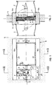
- the fire damper is intended for closing a passage opening 1 of a ventilation duct 2 (FIG. 2), in which flow-conducting internals 3 are provided, between which the flap wing 4 is placed in an open position in a flow-favorable manner. It is arranged in a firewall 5, in which a recess is provided, which is extended relative to the passage opening 1 on three sides - to the right, up and down in FIG. 1 - by the width of a frame 6; on the fourth page, d. H. 1 to the left, the passage opening 1 is delimited by a transverse wall 8, behind which a chamber 7 is provided for receiving the drive for the flap wing 4.
- the two lateral boundaries of the recess form vertical outer walls 9; the transverse wall 8 and the outer walls 9 are joined horizontally at the top by a lintel 10a and at the bottom by a ledge 10b to form the frame 6 inserted into the recess, e.g. B. screwed together.
- the drive which is only indicated schematically, consists of a compressed air cylinder 11 suspended in the chamber 7 at the lintel 10a of the frame 6, to which pressure medium is supplied via a line 12.
- the compressed air cylinder 11 With the flap wing 4, the compressed air cylinder 11 is connected via a piston rod 13 (FIG. 3) which engages with its end on a fork-shaped lever 14 via an axis 18; this in turn is part of a hub 15 which sits on a shaft journal 16 of the flap 4.
- bearing bushes 17 are inserted in the middle; in the bearing bush 17 of the right outer wall 9 in Fig. 1 and in that of the transverse wall 8, the shaft journals 16 of the flap wing 4 are mounted in a manner to be described in more detail, while the bearing bush 17 in the left outer wall 9 as an entry opening into the chamber 7 for the pressure medium power 12 is used.
- the supply of the pressure medium line 12 - and likewise of control and signal lines, not shown - to the bearing bush 17 of the left outer wall 9 takes place through a plastic pipe 19 laid in the firewall, as is customary for the guidance of lines to be subsequently pulled into concrete walls.
- the chamber 7 is covered on both sides by covers 20 which are fastened in the frame 6, for example with the aid of screws 21.
- the covers 20 can also be constructed similarly to the flap 4, the construction of which is described in more detail.
- the frame 6 inserted into the recess of the firewall 5 is constructed in such a way that thermal bridges in directions perpendicular to the firewall 5 - for example by metal parts passing through in this direction - are avoided as far as possible.
- the parts of the frame 6, that is to say the walls 8 and 9, and the horizontal elements 10a and 10b are therefore delimited on their narrow sides by metal frameworks 23 (FIG. 4) which are not connected to one another and which are poured with a cast body 24 made of refractory lightweight concrete and via anchors 25 are additionally anchored.
- Struts 25a leading from the metal frames 23 into the cast body 24 serve to fasten anchor rails 26, as are customary as assembly strips in concrete bodies.
- the bearing bushes 17 are additionally cast into the walls 8 and 9.
- a frame 27 (FIG. 5) made of an asbestos fiber material is provided as the load-bearing element of the flap wing 4;
- the shaft journals 16 are fastened by means of band irons 28 screwed to it, with which the flap wing 4 is rotatably mounted in the bearing bushes 17.
- These shaft journals 16 are centered relative to one another by an angular intermediate piece 29 (FIG. 2) which is slidably connected to the shaft journals 16 by belts 30 wrapping around both parts in such a way that the shaft journals 16 can perform unhindered thermal movements relative to the intermediate piece 29.
- the shaft journals 16, the band irons 28, the intermediate piece 29 and the bands 30 are the only metal parts of the flap wing 4; apart from the externally guided shaft journals 16, they are arranged inside the frame 27, and therefore largely shielded from heat, the interior of the frame 27 being additionally filled with mineral wool 31 and covered on the outside by asbestos plates 32 (FIG. 2).
- thermal bridges are largely avoided in it too, because on the one hand the metal content is very low and on the other hand there are no continuous metal connections perpendicular to its surface.
- the shaft journals 16 for the flap wing 4 are supported in the bearing bushes 17 via spherical plain bearings 33 in order, as mentioned, to reduce the influence of inaccuracies in the concrete structure on the storage and functionality of the flap wing 4.
- the fixed part of the bearing 33 forms a ring 34 which is pressed by a spacer bush 35 against a shoulder in the bearing bush 17; it is concave in the shape of a spherical shell and receives a second ring 36 which sits on the shaft journal 16 and is curved on the outside.
- the bearing bush 17 shown in FIG. 6, which is seated in the right outer wall 9 of FIG. 1, is closed to the outside of the firewall 5 by a cover disk 37, for example soldered on.
- the bearing bush 17 is covered by a cover 38 made of fire-resistant material, for example Eternit, which is fastened to the outer wall 9.
- the cover 38 has at least on its outside facing the flap wing 4 a smooth surface relative to the concrete of the frame 6; this serves as a sliding surface for a felt 39 made of fire-resistant material, for example made of graphite, attached to the flap wing 4.
- the felt 39 which is inserted in a slightly compressed form between the flap 4 and the cover 38, on the one hand brings about a fire-resistant seal between these parts which are moved relative to one another and protects other the shaft journal 16 before overheating.
- the closed flap wing 4 rests on seals 22 which run in the circumferential direction of the passage opening 1 (FIG. 1).
- the seals 22 contain a deformable, elastic cord 40 made of refractory material, for example of a mineral wool based on silicate; this is held by a bracket 41 made of sheet metal along the circumference of the passage opening 1 on the walls of the frame 6.
- the bracket 41 is stepped because of the greater flexibility against thermal expansion and bent to increase its stability at both ends to form loops.
- the clips 42 While one end of the holder 41 presses the cord 40 against the wall 9, the other end is held by clips 42, which are distributed over the circumference of the passage opening 1 in the anchor rails 26.
- the clips 42 have an elongated hole 43 (FIG. 6) in order to enable the sealing cord 40 to be adjusted relative to or infeed in the direction of the closed flap wing 4.
- An anchor rail screw 44 protrudes through the elongated hole 43 for fastening the clamps 42 in the anchor rail 26, with which the clamp 42 is clamped on the anchor rail 26 by a washer 45 and a nut 46. As shown in FIG.
- the free ends of the sealing elements 22 protrude into cutouts of the cover 38, the deformability and the elasticity of the sealing cord 40 being butted against the cover 38 both in the direction of its longitudinal direction, which extends in the circumferential direction of the passage opening 1, and also allow perpendicular to it during assembly; In this way, a secure seal between the free ends of the sealing cord 40, which is not necessarily continuous in a rotary flap, and the flap wing 4 or its shaft is ensured.
Landscapes
- Engineering & Computer Science (AREA)
- General Engineering & Computer Science (AREA)
- Emergency Management (AREA)
- Chemical & Material Sciences (AREA)
- Public Health (AREA)
- Combustion & Propulsion (AREA)
- Mechanical Engineering (AREA)
- Health & Medical Sciences (AREA)
- Business, Economics & Management (AREA)
- Building Environments (AREA)
- Load-Bearing And Curtain Walls (AREA)
- Clamps And Clips (AREA)
- Insulated Conductors (AREA)
- Special Wing (AREA)
- Air-Flow Control Members (AREA)
- Bidet-Like Cleaning Device And Other Flush Toilet Accessories (AREA)
- Fire-Detection Mechanisms (AREA)
- Ultra Sonic Daignosis Equipment (AREA)
Priority Applications (1)
| Application Number | Priority Date | Filing Date | Title |
|---|---|---|---|
| AT80102177T ATE3000T1 (de) | 1979-07-03 | 1980-04-23 | Brandmauer. |
Applications Claiming Priority (2)
| Application Number | Priority Date | Filing Date | Title |
|---|---|---|---|
| CH619379 | 1979-07-03 | ||
| CH6193/79 | 1979-07-03 |
Publications (2)
| Publication Number | Publication Date |
|---|---|
| EP0020921A1 EP0020921A1 (de) | 1981-01-07 |
| EP0020921B1 true EP0020921B1 (de) | 1983-04-13 |
Family
ID=4305728
Family Applications (1)
| Application Number | Title | Priority Date | Filing Date |
|---|---|---|---|
| EP80102177A Expired EP0020921B1 (de) | 1979-07-03 | 1980-04-23 | Brandmauer |
Country Status (5)
| Country | Link |
|---|---|
| EP (1) | EP0020921B1 (da) |
| AT (1) | ATE3000T1 (da) |
| DE (1) | DE3062698D1 (da) |
| DK (1) | DK276580A (da) |
| ES (1) | ES491880A0 (da) |
Cited By (1)
| Publication number | Priority date | Publication date | Assignee | Title |
|---|---|---|---|---|
| WO2004072531A1 (en) * | 2003-02-11 | 2004-08-26 | Truss Holdings Pty. Ltd. | Damper with rotary valve |
Families Citing this family (2)
| Publication number | Priority date | Publication date | Assignee | Title |
|---|---|---|---|---|
| FR2717088B1 (fr) * | 1994-03-09 | 1996-04-19 | Vraco Sa | Clapet coupe feu. |
| RU2742387C1 (ru) * | 2020-04-27 | 2021-02-05 | Геннадий Петрович Касперович | Противопожарный клапан |
Family Cites Families (3)
| Publication number | Priority date | Publication date | Assignee | Title |
|---|---|---|---|---|
| FR2110535A5 (da) * | 1970-10-21 | 1972-06-02 | Etu Rech Ventil Aerau | |
| DE2259656A1 (de) * | 1972-12-01 | 1974-06-20 | Nordluft Norddeutsche Ges Fuer | Mit einer schwenkbaren, unter der wirkung einer schliesskraft stehenden feuerschutzklappe ausgestattetes einbaugehaeuse fuer lufttechnische anlagen |
| DE2554211A1 (de) * | 1975-12-02 | 1977-06-08 | Mabag Luft & Klimatechnik | Betaetigungsvorrichtung fuer eine absperrvorrichtung fuer feuer und rauch in lueftungsleitungen |
-
1980
- 1980-04-23 DE DE8080102177T patent/DE3062698D1/de not_active Expired
- 1980-04-23 EP EP80102177A patent/EP0020921B1/de not_active Expired
- 1980-04-23 AT AT80102177T patent/ATE3000T1/de not_active IP Right Cessation
- 1980-05-27 ES ES491880A patent/ES491880A0/es active Granted
- 1980-06-27 DK DK276580A patent/DK276580A/da unknown
Cited By (1)
| Publication number | Priority date | Publication date | Assignee | Title |
|---|---|---|---|---|
| WO2004072531A1 (en) * | 2003-02-11 | 2004-08-26 | Truss Holdings Pty. Ltd. | Damper with rotary valve |
Also Published As
| Publication number | Publication date |
|---|---|
| DK276580A (da) | 1981-01-04 |
| DE3062698D1 (en) | 1983-05-19 |
| ES8102822A1 (es) | 1981-02-16 |
| ATE3000T1 (de) | 1983-04-15 |
| EP0020921A1 (de) | 1981-01-07 |
| ES491880A0 (es) | 1981-02-16 |
Similar Documents
| Publication | Publication Date | Title |
|---|---|---|
| DE3873509T2 (de) | Vorrichtung zum umlenken einer gasstroemung. | |
| DE19600369C2 (de) | Brandschutzeinrichtung zur Abschottung einer Rohrleitung | |
| DD148695A5 (de) | Feuersichere leitungsdurchfuehrung | |
| DE3138753A1 (de) | Feuersicheres verstellorgan fuer ein absperrorgan | |
| DE2232482C2 (de) | Lüftungsanlage | |
| DE69102084T2 (de) | Schieberventil. | |
| DE2437261A1 (de) | Doppelwandige metalltuer in verbundbauweise | |
| EP0020921A1 (de) | Brandmauer | |
| DE8024158U1 (de) | Brandschutzklappe | |
| DE2708109A1 (de) | Feuerschutzklappe fuer kanaele von klima- und belueftungsanlagen | |
| DE2342531A1 (de) | Absperr- und drosseleinrichtung fuer lueftungs- und klimasysteme | |
| DE2824306C2 (de) | Absperrvorrichtung an Gasleitungen großen Querschnitts | |
| EP1038555A2 (de) | Brandschutzklappe | |
| EP0622588B2 (de) | Absperrvorrichtung für Kanäle mit grossen Querschnitten, insbesondere für Abgas- und Rauchgaskanäle von Kraftwerken | |
| DE3140043C2 (de) | Brandschutzklappe | |
| DE2548785A1 (de) | Gekapseltes ventil | |
| DE1149368B (de) | Kreuzstrom-Roehrenwaermetauscher mit Vorkehrungen gegen das Vermischen der beiden waermetauschenden Medien | |
| DE3121080A1 (de) | Luftauslass mit verstellbaren strahlleiteinrichtungen | |
| DE3717174C2 (de) | Feuerschutzklappe | |
| DE1604250A1 (de) | Gehaeuse fuer eine Zentralsektion einer Lueftungsanlage sowie Anschlussvorrichtung fuer Verbindung solcher Gehaeuse und Eckband fuer ein derartiges Gehaeuse | |
| DE471750C (de) | Regenerative Waermeaustauschvorrichtung, insbesondere zur Vorwaermung von Verbrennungsluft | |
| DE2162926B2 (de) | Beheizbare Raumschalung | |
| EP0445613A1 (de) | Brandschutzkasten | |
| DE6913656U (de) | Elektrischer raumheizkoerper. | |
| DE19950891A1 (de) | Regenerative Nachverbrennungsvorrichtung |
Legal Events
| Date | Code | Title | Description |
|---|---|---|---|
| PUAI | Public reference made under article 153(3) epc to a published international application that has entered the european phase |
Free format text: ORIGINAL CODE: 0009012 |
|
| 17P | Request for examination filed |
Effective date: 19800423 |
|
| AK | Designated contracting states |
Designated state(s): AT BE DE FR GB IT NL SE |
|
| ITF | It: translation for a ep patent filed | ||
| GRAA | (expected) grant |
Free format text: ORIGINAL CODE: 0009210 |
|
| AK | Designated contracting states |
Designated state(s): AT BE DE FR GB IT NL SE |
|
| PG25 | Lapsed in a contracting state [announced via postgrant information from national office to epo] |
Ref country code: NL Effective date: 19830413 Ref country code: BE Effective date: 19830413 |
|
| REF | Corresponds to: |
Ref document number: 3000 Country of ref document: AT Date of ref document: 19830415 Kind code of ref document: T |
|
| PG25 | Lapsed in a contracting state [announced via postgrant information from national office to epo] |
Ref country code: AT Effective date: 19830423 |
|
| ET | Fr: translation filed | ||
| REF | Corresponds to: |
Ref document number: 3062698 Country of ref document: DE Date of ref document: 19830519 |
|
| NLV1 | Nl: lapsed or annulled due to failure to fulfill the requirements of art. 29p and 29m of the patents act | ||
| PG25 | Lapsed in a contracting state [announced via postgrant information from national office to epo] |
Ref country code: FR Free format text: LAPSE BECAUSE OF NON-PAYMENT OF DUE FEES Effective date: 19831229 |
|
| PG25 | Lapsed in a contracting state [announced via postgrant information from national office to epo] |
Ref country code: DE Effective date: 19840103 |
|
| REG | Reference to a national code |
Ref country code: FR Ref legal event code: ST |
|
| GBPC | Gb: european patent ceased through non-payment of renewal fee | ||
| PG25 | Lapsed in a contracting state [announced via postgrant information from national office to epo] |
Ref country code: SE Effective date: 19860413 |
|
| PG25 | Lapsed in a contracting state [announced via postgrant information from national office to epo] |
Ref country code: GB Effective date: 19881118 |
|
| EUG | Se: european patent has lapsed |
Ref document number: 80102177.5 Effective date: 19830408 |
|
| PLBE | No opposition filed within time limit |
Free format text: ORIGINAL CODE: 0009261 |
|
| STAA | Information on the status of an ep patent application or granted ep patent |
Free format text: STATUS: NO OPPOSITION FILED WITHIN TIME LIMIT |