EP0023769A1 - Appareil et procédé pour la séparation de particules solides d'un courant de mélange gaz-solides en phase mixte - Google Patents
Appareil et procédé pour la séparation de particules solides d'un courant de mélange gaz-solides en phase mixte Download PDFInfo
- Publication number
- EP0023769A1 EP0023769A1 EP80302269A EP80302269A EP0023769A1 EP 0023769 A1 EP0023769 A1 EP 0023769A1 EP 80302269 A EP80302269 A EP 80302269A EP 80302269 A EP80302269 A EP 80302269A EP 0023769 A1 EP0023769 A1 EP 0023769A1
- Authority
- EP
- European Patent Office
- Prior art keywords
- solids
- separator
- gas
- outlet
- chamber
- Prior art date
- Legal status (The legal status is an assumption and is not a legal conclusion. Google has not performed a legal analysis and makes no representation as to the accuracy of the status listed.)
- Granted
Links
- 239000007787 solid Substances 0.000 title claims abstract description 162
- 238000000034 method Methods 0.000 title claims abstract description 15
- 238000000926 separation method Methods 0.000 claims abstract description 51
- 230000008859 change Effects 0.000 claims abstract description 7
- 239000007789 gas Substances 0.000 claims description 126
- 230000003628 erosive effect Effects 0.000 claims description 17
- 238000010791 quenching Methods 0.000 claims description 12
- 230000005484 gravity Effects 0.000 claims description 8
- 239000002245 particle Substances 0.000 claims description 7
- 230000000694 effects Effects 0.000 claims description 6
- 230000003068 static effect Effects 0.000 claims description 5
- 238000009413 insulation Methods 0.000 claims description 3
- 239000012530 fluid Substances 0.000 claims description 2
- 238000007493 shaping process Methods 0.000 claims 3
- 239000011261 inert gas Substances 0.000 claims 2
- 229910010293 ceramic material Inorganic materials 0.000 claims 1
- 238000002347 injection Methods 0.000 claims 1
- 239000007924 injection Substances 0.000 claims 1
- 239000007921 spray Substances 0.000 claims 1
- 238000010348 incorporation Methods 0.000 abstract 1
- 239000012071 phase Substances 0.000 description 28
- 238000006243 chemical reaction Methods 0.000 description 15
- VYPSYNLAJGMNEJ-UHFFFAOYSA-N Silicium dioxide Chemical compound O=[Si]=O VYPSYNLAJGMNEJ-UHFFFAOYSA-N 0.000 description 8
- 230000008569 process Effects 0.000 description 6
- 239000003054 catalyst Substances 0.000 description 5
- 239000000463 material Substances 0.000 description 5
- PNEYBMLMFCGWSK-UHFFFAOYSA-N aluminium oxide Inorganic materials [O-2].[O-2].[O-2].[Al+3].[Al+3] PNEYBMLMFCGWSK-UHFFFAOYSA-N 0.000 description 4
- 238000013461 design Methods 0.000 description 4
- 238000010586 diagram Methods 0.000 description 4
- 230000001105 regulatory effect Effects 0.000 description 4
- 239000000377 silicon dioxide Substances 0.000 description 4
- 230000015556 catabolic process Effects 0.000 description 3
- 230000007423 decrease Effects 0.000 description 3
- 238000006731 degradation reaction Methods 0.000 description 3
- 239000000203 mixture Substances 0.000 description 3
- 238000013341 scale-up Methods 0.000 description 3
- 239000007790 solid phase Substances 0.000 description 3
- 230000002411 adverse Effects 0.000 description 2
- 230000008901 benefit Effects 0.000 description 2
- 230000015572 biosynthetic process Effects 0.000 description 2
- 238000004523 catalytic cracking Methods 0.000 description 2
- 230000003197 catalytic effect Effects 0.000 description 2
- 230000003247 decreasing effect Effects 0.000 description 2
- 230000001419 dependent effect Effects 0.000 description 2
- 230000003292 diminished effect Effects 0.000 description 2
- 229930195733 hydrocarbon Natural products 0.000 description 2
- 150000002430 hydrocarbons Chemical class 0.000 description 2
- 238000004519 manufacturing process Methods 0.000 description 2
- JTJMJGYZQZDUJJ-UHFFFAOYSA-N phencyclidine Chemical class C1CCCCN1C1(C=2C=CC=CC=2)CCCCC1 JTJMJGYZQZDUJJ-UHFFFAOYSA-N 0.000 description 2
- 230000008929 regeneration Effects 0.000 description 2
- 238000011069 regeneration method Methods 0.000 description 2
- 229910010271 silicon carbide Inorganic materials 0.000 description 2
- 230000001154 acute effect Effects 0.000 description 1
- 150000001336 alkenes Chemical class 0.000 description 1
- 238000005266 casting Methods 0.000 description 1
- 238000006555 catalytic reaction Methods 0.000 description 1
- 239000000571 coke Substances 0.000 description 1
- 238000010276 construction Methods 0.000 description 1
- 230000007547 defect Effects 0.000 description 1
- 238000004231 fluid catalytic cracking Methods 0.000 description 1
- 238000010438 heat treatment Methods 0.000 description 1
- 239000012535 impurity Substances 0.000 description 1
- 238000007689 inspection Methods 0.000 description 1
- 238000009434 installation Methods 0.000 description 1
- 238000012423 maintenance Methods 0.000 description 1
- 230000007246 mechanism Effects 0.000 description 1
- 230000004048 modification Effects 0.000 description 1
- 238000012986 modification Methods 0.000 description 1
- 238000000746 purification Methods 0.000 description 1
- 230000009467 reduction Effects 0.000 description 1
- 230000002829 reductive effect Effects 0.000 description 1
- 238000012360 testing method Methods 0.000 description 1
- 238000004227 thermal cracking Methods 0.000 description 1
Images
Classifications
-
- B—PERFORMING OPERATIONS; TRANSPORTING
- B01—PHYSICAL OR CHEMICAL PROCESSES OR APPARATUS IN GENERAL
- B01D—SEPARATION
- B01D45/00—Separating dispersed particles from gases or vapours by gravity, inertia, or centrifugal forces
- B01D45/04—Separating dispersed particles from gases or vapours by gravity, inertia, or centrifugal forces by utilising inertia
- B01D45/06—Separating dispersed particles from gases or vapours by gravity, inertia, or centrifugal forces by utilising inertia by reversal of direction of flow
Definitions
- Chemical reaction systems utilizing solids in contact with a gaseous or vaporized stream have long been employed.
- the solids may participate in the reaction as catalyst, provide heat required for an endothermic reaction, or both.
- the solids may provide a heat sink in the case of an exothermic reaction.
- Fluidized bed reactors have substantial advantages, most notably an isothermal temperature profile. However, as residence time decreases the fluidized bed depth becomes shallower and increasingly unstable. For this reason tubular reactors employing solid-gas contact in pneumatic flow have been used and with great success, particularly in the catalytic cracking of hydrocarbons to produce gasolines where reaction residence times are between 2 and 5 seconds.
- reaction systems specifically catalytic reactions at low or moderate temperatures, quench of the product gas is undesirable from a process standpoint. In other cases the quench is ineffective in terminating the reaction. Thus, these reaction systems require immediate separation of the phases to remove catalyst from the gas phase. Once the catalyst has been removed, the mechanism for reaction is no longer present.
- Nicholson U.S. Patent 2,737,479 combines reaction and separation steps within a helically wound conduit containing a plurality of complete turns and having a plurality of gaseous product drawoffs on the inside surface of the conduit to separate solids from the gas phase by centrifugal force. Solids gravitate to the outer periphery of the conduit, while gases concentrate at the inner wall, and are removed at the drawoffs. Although the Nicholson reactor-separator separates the phases rapidly, it produces a series of gas product streams each at a different stage of feed conversion. This occurs because each product stream removed from the multiple product draw offs which are spaced along the conduit is exposed to the reaction conditions for a different time period in a reaction device which has inherently poor contact between solids and gases.
- Ross et al U.S. Patent 2,878,891 attempted to overcome this defect by appending to a standard riser reactor a modification of Nicholson's separator.
- Ross's separator is comprised of a curvi-linear conduit making a separation through a 180° to 240° turn. Centrifugal force directs the heavier solids to the outside wall of the conduit allowing gases that accumulate at the inside wall to be withdrawn through a single drawoff. While the problem of product variation is decreased to some extent, other drawbacks of the Nicholson apparatus are not eliminated.
- Both devices effect separation of gas from solids by changing the dir-ction of the gas 90° at the withdraw point, while allowing solids to flow linearly to the separator outlet. Becuase solids do not undergo a directional change at the point of separation, substantial quantities of gas flow past the withdraw point to the solids outlet. For this reason both devices require a conventional separator at the solids outlet to remove excess gas from the solid particles. Unfortunately, product gas removed in the conventional separator has remained in intimate contact with-the solids, has not been quenched, and is, therefore, severely degraded.
- Pappas U.S. Patent 3,074,878 devised a low residence time separator using deflection means wherein the solid gas stream flowing in a tubular conduit impinges upon a deflector plate causing the solids, which have greater inertia, to be projected away from a laterally disposed gas withdrawal conduit located beneath said deflector plate.
- solids do not change direction while the gas phase changes direction relative to the inlet stream by only 90 0 resulting in inherently high entrainment of solids in the effluent gas.
- baffles placed across the withdrawal conduit reduce entrainment, these baffles as well as the deflector plate are subject to very rapid erosion in severe operating conditions of high temperature and high velocity.
- An additional object of this invention is to provide a separation system that obtains essentially complete separation of gas from the solids phase, although a controlled flow of gas with the solids phase is consistent with the operation of the device.
- Another object of this invention is to provide a separation system to provide essentially complete separation of solids from the mixed phase stream.
- a further object is to effect a separation at high temperature and/or high velocity conditions with a minimum of gas product degradation.
- Another objectof this invention is to provide a method for rapidly attaining a primary separation of solids from a mixed phase gas-solid stream.
- the separation device and system of the present invention rapidly disengages particulate solids from a mixed phase gas-solids stream with a minimum of erosion.
- the separator consists of a chamber having an inlet at one end and a solids outlet at the other with the gas outlet therebetween. Each inlet and outlet is normal to the basic flow pattern within the separator.
- the gas outlet is oriented so that the gas portion of the feed undergoes a 180° change in direction, while the solids outlet is preferably aligned for downflow. Solids are projected by centrifugal force to a wall of the separator normal to and opposite to the inlet as the gas changes direction 180° forming thereat a bed of solids having an arcuate surface configuration of approximately 90° upon which subsequent solids impinge.
- the curve of the bed extends to the solids outlet and forms a path along which solids flow Erosion of the wall opposite the inlet of the separator is diminished or eliminated by formation of the bed, which also aids in establishing a U-shaped 180° flow pattern of the gas stream.
- the separation system is comprised of the primary separator, a secondary separator, and a stripping vessel.
- the gas outlet of the primary separator is connected to the secondary separator via a conduit, while the stripping vessel is similarly connected to the solids outlet.
- Pressure regulating means are used to control the flow of gas to the stripping vessel.
- a weir is used to establish a more stable bed, although a weirless separator may be used.
- the solids outlet flow path may be restricted by other means which aid in the 'deaeration of solids.
- the loss of gas entrained with the solids phase is small because of the directional changed imposed on both gas and solid phases.
- the separator is designed within several geometric constraints in order to maximize the separation efficiency. It is essential that the flow path have a rectangular cross section in order to obtain good efficiency. To obtain high efficiencies a separator with an inlet inside diameter D i should preferably have a flow path height of at least D i or 4 inches, whichever is greater. Similarly, the width of the flow path should be. between 0.75 and 1.25 D i while the distance between inlet and gas outlet centerlines should be no greater than 4 times D i .
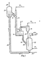
- FIG. 1 is a schematic flow diagram showing the installation of the separator system of the present invention in a typical tubular reactor system handling dilute phase solid-gas mixtures.
- Solids and gas enter tubular reactor ,13 through lines 11 and 12 respectively.
- the reactor effluent flows directly to separator 14 where a separation into a gas phase and a solids phase stream is effected.
- the gas phase is removed via line 15, while the solid phase is sent to stripping vessel 22 via line 16.
- an inline quench of the gas leaving the separator via line 15 may be made by injecting quench material from line 17.
- the product gas contains residual solids and is sent to a secondary separator 18, preferably a conventional cyclone.
- Quench material should be introduced in line 15 in a way that precludes back flow of quench material to the separator.
- the residual solids are removed from separator 18 via line, 21, while essentially solids free product gas is removed overhead through line 19.
- Solids from lines 16 and 21 are stripped of gas impurities in fluidized bed stripping vessel 22 using steam or other inert fluidizing gas admitted via line 23. Vapors are removed from the stripping vessel through line 24 and, if economical or if need be, sent to downstream purification units. Stripped solids removed from the vessel 22 through line 25 are sent to regeneration vessel 27 using pneumatic transport gas from line 26. Off gases are removed from the regenerator through line 28. After regeneration the solids are then recycled to reactor 13 via line 11.
- the separator 14 should disengage solids rapidly from the reactor effluent in order to prevent product degradation and ensure optimal yield and selectivity- of the desired pro-. ducts. Further, the separator 14 operates in a manner that eliminates or at least significantly reduced the amount of gas entering the stripping vessel 22 inasmuch-as this portion of the gas product would be severely degraded by remaining in intimate contact with the solid phase. This is accomplished with a positive seal which has been provided between the separator 14 and the stripping vessel 22. Finally, the separator 14 operates so that erosion is minimized despite high temperature and high velocity conditions that are inherent in many of these processes. The separator system of the present invention is designed to meet each one of these criteria as is described below.
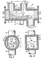
- FIG. 2 is a cross sectional elevational view showing the preferred embodiment of solids-gas separation device 14 of the present invention.
- the separator 14 is provided with a separator shell 37 and is comprised of a solids-gas disengaging chamber 31 having an inlet 32 for the mixed phase stream, a gas phase outlet 33, and a solids phase outlet 34.
- the inlet 32 and the solids outlet 34 are preferably located at opposite ends of the chamber 31, while the gas outlet 33 lies at a point therebetween.
- Clean-out and maintenance manways 35 and 36 may be provided at either end of the chamber 31.
- the separator shell 37 and manways 35 and 36 preferably are lined with erosion resistent linings 38, 39 and 41 respectively which may be required if solids at high velocities are encountered.
- Typical commercially available materials for erosion resistent lining include Carborundum Precase Carbofrax D, Carborundum Precast Alfrax 201 or their equivalent.
- a thermal insulation lining 40 may be placed between shell 37 and lining 38 and between the man-. ways and their respective erosion resistent linings when the separator is to be used in high temperature service. Thus, process temperatures above 1500°F (870°C) are not inconsistent with the utilization of this device.
- Figure 3 shows a cutaway view of the separator along section 3-3.
- the separator 14 shell is preferably fabricated from cylindrical sections such as pipe 50, although-other materials may, of course, be used. It is essential that longitudinal side walls 51 and 52 should be rectilinear, or slightly arcuate as indicated by the dotted lines 51a and 52a.
- flow path 31A through the separator is essentially rectangular in cross section having a height H and width W as shown in Figure 3.
- the embodiment shown in Figure 3 defines the geometry of the flow path by adjustment of the lining width for walls 51 and 52. Alternatively, baffles, inserts, weirs or other means may be used.
- FIG 4 is a cutaway view along Section 3-3 of Figure 2 wherein the separation shell 37 is fabricated from a rectangular conduit. Because the shell 37 has rectilinear walls 51 and 52 it is not necessary to adjust the width of the flow path with a thickness of lining. Linings 38 and 40 could be added for erosion and thermal resistence respectively.
- inlet 32 and outlets 33 are disposed normal to flow path 3lA (shown in Figure 3) so that the incoming mixed phase stream from inlet 32 is required to undergo a 90° change in direction upon entering the chamber.
- the gas phase outlet 33 is also oriented so that the gas phase upon leaving the separator has completed a 180° change in direction.
- Centrifugal force propels the solid particles to the wall 54 opposite inlet 32 of the chamber 31, while the gas portion, having less momentum, flows through the vapor space of the chamber 31.
- solids impinge on the wall 54, but subsequently accumulate to form a static bed of solids 42 which ultimately form in a surface configuration having a curvilinear arc 43 of approximately 90°.
- Solids impinging upon the bed are moved along the curvilinear arc 43 to the solids outlet 34, which is preferably oriented for downflow of solids by gravity.
- the exact shape of the ,arc 43 is determined by the geometry of the particular separator and the inlet stream parameters such as velocity, mass flowrate, bulk density, and particle size.
- Separator efficiency defined as the removal of solids from the gas phase leaving through outlet 33 is, therefore, not affected adversely by high inlet velocities, up to 150 ft/sec. and the separator 14 is operable over a wide range of dilute phase densities, preferably between 0.1 and 10.0 1bs/ft 3 .
- the separator 14 of the present invention achieves efficiencies of about 80%, although the preferred embodiment, discussed below, can obtain over 90% removal of solids.
- separator efficiency is dependent upon separator geometry inasmuch-as the flow path-must be essentially rectangular and the relationship between height H, and the sharpness of the U-bend in the gas flow.
- the height of flow path H should be at least equal to the value of D i or 4 inches in height, whichever is greater.
- Practice teaches that if H is less than D i or 4 inches the incoming stream is apt to disturb the bed solids 42 thereby re-entraining solids in the gas product leaving through outlet 33.
- H is of the order of twice D i to obtain even greater separation efficiency. While not otherwise limited, it is apparent that too large an H eventually merely increases residence time without substantive increases in efficiency.
- the width W of the flow path- is preferably between 0.75 and 1.25 times D i , most preferably between 0.9 and 1.10 D i .
- Outlet 33 may be of any inside diameter. However, velocities greater than 75 ft/sec can cause erosion because of residual solids entrained in the gas.
- the inside diameter of outlet 34 should be sized so that a pressure differential between the stripping vessel 22 shown in Figure 1 and the separator 14 exist such that a static height of solids is formed in solids outlet line 16.
- the static height of solids in line 16 forms a positive seal which prevents gases from entering the stripping vessel 22.
- the magnitude of the pressure differential between the stripping vessel 22 and the separator 14 is determined by the force required to move the solids in hulk flow to the solids outlet 34 as well as the height of solids in line 16. As the differential increases the net flow of gas to the stripping vessel 22 decreases. Solids, having gravitational momentum, overcome the differential, while gas preferentially leaves through the gas outlet 33.
- the pressure regulating means may include a check of "flapper" valve 29 at the outlet of line 16, or a pressure control 29a device on vessel 22.
- the pressure may be regulated by selecting the size of the outlet 34 and conduit 16 to obtain hydraulic forces acting on the system that set the flow of gas to the stripper 32. While such gas is degraded, we have found that an increase in separation efficiency occurs with a bleed of gas to the stripper of less than 10%, preferably between 2 and 7%. Economic and process considerations would dictate whether this mode of operation should be used. It is also possible to design the system to obtain a net backflow of gas from the stripping vessel. This gas flow should be less than lo$ of the total feed gas rate.
- residences times as low as 0.1 seconds or less may be obtained, even in separators having inlets over 3 feet in diameter. Scale-up to 6 feet in diameter is possible in many systems where residence times approaching 0.5 seconds are allowable.
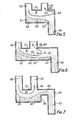
- a weir 44 is placed across the flow path at a point at or just beyond the gas outlet to establish a positive height of solids prior to solids outlet 34.
- a weir or an equivalent restriction
- the weir 44 establishes a bed which has a crescent shaped curvilinear arc 43 of slightly more than 90°. An arc of this shape diverts gas towards the gas outlet and creates the U-shaped gas flow pattern illustrated diagrama- tically in line 45 in Figure 2.
- the separator of Figure 6 is a schematic diagram of another embodiment of the separator 14, said separator 14 having an extended separation chamber in the longitudinal dimension.
- L is preferably less than or equal to 5 D i .
- the gas flow pattern 61 does not develop the preferred U-shape, a crescent shaped arc is obtained which limits erosion potential to area 64.
- Embodiments shown by Figures 5 and 6 are useful when the solids loading of the incoming stream is low.
- the embodiment of Figure 5 also has the minimum pressure loss and may be used when the velocity of the incoming stream is low.
- a stepped solids outlet 65 having a section 66 co-linear with the flow path. as well as a gravity flow section 67.
- Wall 68 replaces weir 44, and arc 43 and flow pattern 45 are similar to the preferred embodiment of Figure 2. Because solids accumulate in the restricted co-linear section 66, pressure losses are greater. This embodiment, then, is not preferred where the incoming stream is at low velocity and cannot supply sufficient force to expel the solids through outlet 65. However, because of the restricted solids flow path, better deaeration is obtained and gas losses are minimal.
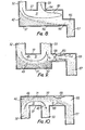
- Figure 8 illustrates another embodiment of the separator 14 of Figure 7 wherein the solids outlet is not stepped. Although a weir is not used, the outlet restricts solids flow which helps form the bed 42. As in Figure 6, an extended L distance between the gas outlet and solids outlet may be used.
- the separator of Figure 7 or 8 may be used in conjunction with a venturi, an orifice, or an equivalent flow restriction device as shown in Figure 9.
- the venturi 69 having dimensions D (diameter at venturi inlet), D vt (diameter at venturi throat) and 9 (angle of cone formed by projection of convergent venturi walls) is placed in the co-linear section 66 of the outlet 65 to greatly improve deaeration of solids.
- the embodiment of Figure 10 is a variation of the separator shown in Figure 9.
- inlet 32 and outlet 33 are oriented for use in a riser type reactor. Solids are propelled to the wall 71 and the bed thus formed is kept in place by the force of the incoming stream.
- the inlet stream was comprised of 85 ft. 3 /min of air and 52 1bs./ min. of silica alumina having a bulk denwity of 70 lbs./ft. 3 and an average particle size of 100 microns.
- the stream density was 0.612 lbs./ ft 3 and the operation was performed at ambient temperature and atmospheric pressure.
- the velocity of the incoming stream through the 2 inch inlet was 65.5 ft./sec., while the outlet gas velocity was 85.6 ft./sec. through a 1.75 inch diameter outlet.
- a positive seal of solids in the solids outlet prevented gas from being entrained in the solids leaving the separator.
- Bed solids were stabilized by placing a 0.75 inch weir across the flow path.
- the observed separation efficiency was 89.1% and was accomplished in a gas phase residence time of approximately 0.008 seconds. Efficiency is defined as the percent removal of solids from the inlet stream.
- Example 1 The gas-.solids mixture of Example 1 was processed in a separator having a configuration illustrated by Figure 6.
- the L dimension is 2 inches; all other dimensions are the same as Example 1.
- Example 2 The separator of Example 2 was tested with an inlet stream comprised of 85 ft. 3 /min of air and 102 lbs./min of silica alumina which gave a stream density of 1.18 1bs. /ft. 3 or approximately twice that of Example 2. Separation efficiency improved to 83.8%.
- Example 1 The preferred separator of Example 1 was tested at the inlet flow rate of Example 3. Efficiency increased slightly to 91.3%.
- the separator of Figure 2 was tested at the conditions of Example 1. Although the separation dimensions are specified in Table 1 note that the distance CL between inlet and gas outlet centerlines was 5.875 inches, or about three times the diameter of the inlet. This dimension is outside the most preferred range for CL which is between 1.50 and 2.50 Di. Residence time increased to 0.01 seconds, while efficiency was 73.0%.
- Example 5 Same conditions apply as for Example 5 except that the solids loading was increased to 102 1bs./min to give a stream density of 1.18 lbs./ft. 3 . As observed previously in Examples 3 and 4, the separator efficiency increased with higher solids loading to 90.6%
- the respective velocities were 40 and 90 ft./sec.
- the solids had a bulk density of 70 1bs./ft. 3 and the stream density was 1.37 lbs./ ft 3 .
- Distance CL between inlet and gas outlet centerlines was 11 inches, or 1.83 times the inlet diameter; distance L was zero.
- the bed was stabilized by a 2.25 inch weir, and gas loss was prevented by a positive seal of solids.
- the solids were collected in a closed vessel, and the pressure differential was such that a positive flow of displaced gas from the collection vessel to the separator was observed. This volume was approximately 9.4 ft. 3 /min. Observed separator efficiency was 90.0$ and the gas phase residence time approximately 0.02 seconds.
- Example 7 The separator used in Example 7 was tested with an identical feed of gas and solids. However, the solids collection vessel was vented to the atmosphere and the pressure differential adjusted such that 9% of the feed gas, or 42.5 ft. 3 /min., exited through the solids outlet at a velocity of 3.6 ft./sec. Separator efficiency increased with this positive bleed through the solids outlet to 98.1%.
- the separator of Figure 8 was tested in a unit having a 2 inch inlet and a 1 inch gas outlet.
- the solids outlet was 2 inches in diameter and was located 10 inches away from the gas outlet (dimension L).
- a weir was not used.
- the feed was comprised of 85 ft.3/min. of air and 105 lbs. /min of spent fluid catalytic cracker catalust having a bulk density of 45 1bs./ft. 3 and an average particle size of 50 microns. This gave a stream density of 1.20 lbe. /ft. 3 .
- Gas inlet velocity was 65 ft./sec. while the gas outlet velocity was 262 ft./sec.
- Example 7 there was a positive counter-current flow of displaced gas from the collection vessel to the separator. This flow was approximately 1.7 ft. 3 / min. at a velocity of 1.3 ft./sec. Operation was at ambient temperature and atmospheric pressure. Separator efficiency was 95.0%.
- the separator of Figure 9 was tested on a feed comprised of 85 ft. 3 / min. of air and 78 lbs.Jmin of spent fluid Catalytic Cracking catalyst.
- the inlet was 2 inches in diameter which resulted in a velocity of 65 ft./sec.
- the gas outlet was 1 inch in diameter which resulted in an outlet velocity of 262 ft./sec.
- This separator had a stepped solids outlet with a venturi in the co-linear section of the outlet.
- the venturi mouth was 2 inches in diameter, while the throat was 1 inch..
- a cone of 28.1° was formed by projection of the convergent walls of the venturi.
- An observed efficiencyof 92.6% was measured, and the solids leaving the separator were completely deaerated except for interstitial gas remaining in the solids' voids.
Landscapes
- Chemical & Material Sciences (AREA)
- Chemical Kinetics & Catalysis (AREA)
- Cyclones (AREA)
- Devices And Processes Conducted In The Presence Of Fluids And Solid Particles (AREA)
- Separating Particles In Gases By Inertia (AREA)
Priority Applications (1)
| Application Number | Priority Date | Filing Date | Title |
|---|---|---|---|
| AT80302269T ATE10588T1 (de) | 1979-07-06 | 1980-07-04 | Apparat und verfahren zum abtrennen von feststoffteilchen aus einem feststoff-gas-strom in der mischphase. |
Applications Claiming Priority (2)
| Application Number | Priority Date | Filing Date | Title |
|---|---|---|---|
| US55148 | 1979-07-06 | ||
| US06/055,148 US4288235A (en) | 1979-07-06 | 1979-07-06 | Low residence time solid-gas separation device and system |
Publications (2)
| Publication Number | Publication Date |
|---|---|
| EP0023769A1 true EP0023769A1 (fr) | 1981-02-11 |
| EP0023769B1 EP0023769B1 (fr) | 1984-12-05 |
Family
ID=21995938
Family Applications (1)
| Application Number | Title | Priority Date | Filing Date |
|---|---|---|---|
| EP80302269A Expired EP0023769B1 (fr) | 1979-07-06 | 1980-07-04 | Appareil et procédé pour la séparation de particules solides d'un courant de mélange gaz-solides en phase mixte |
Country Status (21)
| Country | Link |
|---|---|
| US (1) | US4288235A (fr) |
| EP (1) | EP0023769B1 (fr) |
| JP (1) | JPS6018447B2 (fr) |
| AR (1) | AR224014A1 (fr) |
| AT (1) | ATE10588T1 (fr) |
| BR (1) | BR8008739A (fr) |
| CA (1) | CA1151084A (fr) |
| DE (1) | DE3069746D1 (fr) |
| ES (3) | ES493120A0 (fr) |
| FI (1) | FI76498C (fr) |
| IL (1) | IL60521A (fr) |
| IN (1) | IN154591B (fr) |
| MA (1) | MA18899A1 (fr) |
| MX (2) | MX150892A (fr) |
| MY (1) | MY8600098A (fr) |
| PT (1) | PT71489A (fr) |
| SG (1) | SG22885G (fr) |
| SU (1) | SU1085499A3 (fr) |
| WO (1) | WO1981000059A1 (fr) |
| YU (1) | YU42345B (fr) |
| ZA (1) | ZA804043B (fr) |
Families Citing this family (27)
| Publication number | Priority date | Publication date | Assignee | Title |
|---|---|---|---|---|
| US4348364A (en) * | 1979-07-06 | 1982-09-07 | Stone & Webster Engineering Corp. | Thermal regenerative cracking apparatus and separation system therefor |
| US4433984A (en) | 1979-07-06 | 1984-02-28 | Stone & Webster Engineering Corp. | Low residence time solid-gas separation device and system |
| US4556541A (en) * | 1980-07-03 | 1985-12-03 | Stone & Webster Engineering Corporation | Low residence time solid-gas separation device and system |
| US5045176A (en) * | 1981-05-13 | 1991-09-03 | Ashland Oil, Inc. | Carbometallic oil conversion with ballistic separation |
| SE437943B (sv) * | 1983-08-16 | 1985-03-25 | Stal Laval Turbin Ab | Sett att oka en cyklons avskiljningsgrad och cyklonavskiljare for genomforande av settet |
| JPS6189645U (fr) * | 1984-11-16 | 1986-06-11 | ||
| US4756886A (en) * | 1986-04-10 | 1988-07-12 | Stone & Webster Engineering Corporation | Rough cut solids separator |
| US4814067A (en) * | 1987-08-11 | 1989-03-21 | Stone & Webster Engineering Corporation | Particulate solids cracking apparatus and process |
| US5098672A (en) | 1987-08-11 | 1992-03-24 | Stone & Webster Engineering Corp. | Particulate solids cracking apparatus and process |
| US5167795A (en) * | 1988-01-28 | 1992-12-01 | Stone & Webster Engineering Corp. | Process for the production of olefins and aromatics |
| ATE89308T1 (de) | 1989-02-08 | 1993-05-15 | Stone & Webster Eng Corp | Verfahren zur herstellung von olefinen. |
| US5391289A (en) * | 1990-09-04 | 1995-02-21 | Chevron Research And Technology Company | FCC process with rapid separation of products |
| EP0532071B1 (fr) * | 1991-09-09 | 1995-03-15 | Stone & Webster Engineering Corporation | Procédé et appareillage pour séparer du catalyseur de craquage fluidisé à partir des vapeurs hydrocarbonés |
| US5259855A (en) * | 1991-09-09 | 1993-11-09 | Stone & Webster Engineering Corp. | Apparatus for separating fluidized cracking catalysts from hydrocarbon vapor |
| US5314610A (en) * | 1992-05-29 | 1994-05-24 | Abb Lummus Crest Inc. | Staged catalytic cracking process |
| AT399824B (de) * | 1993-11-17 | 1995-07-25 | Scheuch Alois Gmbh | Verfahren und vorrichtung zur staubabscheidung |
| US5389239A (en) * | 1993-11-22 | 1995-02-14 | Texaco Inc. | Control method for direct-coupled FCC riser cyclone |
| AU729703B2 (en) * | 1996-06-10 | 2001-02-08 | Supergold Holdings Pty Ltd | Top stuffing box |
| FI114289B (fi) * | 2000-04-07 | 2004-09-30 | Foster Wheeler Energia Oy | Laite hiukkasten erottamiseksi kuumista kaasuista |
| US6692552B2 (en) | 2001-03-20 | 2004-02-17 | Stone & Webster Process Technology, Inc. | Riser termination device |
| EP1609841A1 (fr) * | 2004-06-22 | 2005-12-28 | Stone & Webster Process Technology, Inc. | Désulfuration et procédé FCC intégré |
| US7429363B2 (en) * | 2005-02-08 | 2008-09-30 | Stone & Webster Process Technology, Inc. | Riser termination device |
| ATE532019T1 (de) * | 2007-08-07 | 2011-11-15 | Thyssenkrupp Polysius Ag | Vorrichtung zur separierung von einem feststoff und einem gas sowie anlage zur zementherstellung |
| AT505750B1 (de) * | 2007-12-21 | 2009-04-15 | Siemens Vai Metals Tech Gmbh | Verfahren und vorrichtung zur grobabscheidung von feststoffpartikeln aus feststoffbeladenen gasen |
| US8383051B2 (en) * | 2009-07-22 | 2013-02-26 | Stone & Webster Process Technology, Inc. | Separating and stripping apparatus for external FCC risers |
| US8177887B2 (en) * | 2010-02-27 | 2012-05-15 | Hewlett-Packard Development Company, L.P. | Aerosol particle collection |
| CN107288599A (zh) * | 2016-03-30 | 2017-10-24 | 中国石油化工股份有限公司 | 治理蒸汽吞吐汽窜的堵调方法 |
Citations (8)
| Publication number | Priority date | Publication date | Assignee | Title |
|---|---|---|---|---|
| DE532653C (de) * | 1927-11-18 | 1931-09-02 | Carl Foerderreuther Dr Ing | Staubabscheider |
| CH284789A (de) * | 1949-05-28 | 1952-08-15 | Waagner Biro Ag | Gasreinigungsverfahren mit Hilfe eines Primär-Staubabscheiders und Staubabscheider zur Durchführung des Verfahrens. |
| US2641335A (en) * | 1946-01-12 | 1953-06-09 | Union Oil Co | Gas-solid separator |
| US2947577A (en) * | 1957-01-15 | 1960-08-02 | Shell Oil Co | Disengaging solids from a lift gas |
| US3056248A (en) * | 1959-07-22 | 1962-10-02 | Metallgesellschaft Ag | Separating apparatus |
| DE1170320B (de) * | 1957-08-19 | 1964-05-14 | Buehler Ag Geb | Flachgebauter Abscheider fuer pneumatische Foerderanlagen |
| GB1033606A (en) * | 1962-11-28 | 1966-06-22 | Wibau Gmbh | Improved device for producing filter material particularly for use in road construction |
| DE2221726A1 (de) * | 1972-05-04 | 1973-11-15 | Karl Dipl-Ing Beckenbach | Verfahren und vorrichtung zur entstaubung von gasen, insbesondere von rauchgasen von kalkoefen |
Family Cites Families (11)
| Publication number | Priority date | Publication date | Assignee | Title |
|---|---|---|---|---|
| US1469702A (en) * | 1923-10-02 | Air-cleaning attachment eor automobile carburetors | ||
| US2328325A (en) * | 1940-06-29 | 1943-08-31 | Standard Oil Co | Powdered catalyst recovery |
| US2439811A (en) * | 1941-05-21 | 1948-04-20 | Kellogg M W Co | Catalytic conversion of hydrocarbons |
| US2698224A (en) * | 1951-12-18 | 1954-12-28 | Phillips Petroleum Co | Catalyst backflow prevention device |
| FR1088435A (fr) * | 1952-12-04 | 1955-03-07 | Standard Oil Dev Co | Séparation des particules entraînées dans des fluides |
| US2737479A (en) * | 1953-07-27 | 1956-03-06 | Exxon Research Engineering Co | Staged separation and stabilization of oil conversion products and apparatus therefor |
| US2878891A (en) * | 1953-10-05 | 1959-03-24 | Exxon Research Engineering Co | Loop separator for gases and solids |
| US3247651A (en) * | 1962-11-27 | 1966-04-26 | Exxon Research Engineering Co | Inertia-type solids de-entrainment device |
| US3443368A (en) * | 1966-07-26 | 1969-05-13 | Shell Oil Co | Tubular centrifugal separators |
| US4219407A (en) * | 1978-01-20 | 1980-08-26 | Mobil Oil Corporation | Fluid cracking process and the method for separating a suspension discharged from a riser cracking zone |
| US4163650A (en) * | 1978-07-24 | 1979-08-07 | Tepco, Incorporated | Portable electronic precipitator |
-
1979
- 1979-07-06 US US06/055,148 patent/US4288235A/en not_active Expired - Lifetime
-
1980
- 1980-07-03 JP JP55501829A patent/JPS6018447B2/ja not_active Expired
- 1980-07-03 FI FI802137A patent/FI76498C/fi not_active IP Right Cessation
- 1980-07-03 WO PCT/US1980/000902 patent/WO1981000059A1/fr not_active Ceased
- 1980-07-03 PT PT71489A patent/PT71489A/pt unknown
- 1980-07-03 YU YU1744/80A patent/YU42345B/xx unknown
- 1980-07-03 BR BR8008739A patent/BR8008739A/pt not_active IP Right Cessation
- 1980-07-04 MX MX183059A patent/MX150892A/es unknown
- 1980-07-04 CA CA000355416A patent/CA1151084A/fr not_active Expired
- 1980-07-04 DE DE8080302269T patent/DE3069746D1/de not_active Expired
- 1980-07-04 EP EP80302269A patent/EP0023769B1/fr not_active Expired
- 1980-07-04 ZA ZA00804043A patent/ZA804043B/xx unknown
- 1980-07-04 AT AT80302269T patent/ATE10588T1/de active
- 1980-07-04 ES ES493120A patent/ES493120A0/es active Granted
- 1980-07-04 MX MX201669A patent/MX161010A/es unknown
- 1980-07-04 AR AR281670A patent/AR224014A1/es active
- 1980-07-05 MA MA19097A patent/MA18899A1/fr unknown
- 1980-07-08 IL IL60521A patent/IL60521A/xx unknown
- 1980-09-10 IN IN1037/CAL/80A patent/IN154591B/en unknown
- 1980-10-07 ES ES495691A patent/ES8107039A1/es not_active Expired
- 1980-10-07 ES ES495692A patent/ES495692A0/es active Granted
-
1981
- 1981-03-05 SU SU813255244A patent/SU1085499A3/ru active
-
1985
- 1985-03-26 SG SG228/85A patent/SG22885G/en unknown
-
1986
- 1986-12-30 MY MY98/86A patent/MY8600098A/xx unknown
Patent Citations (8)
| Publication number | Priority date | Publication date | Assignee | Title |
|---|---|---|---|---|
| DE532653C (de) * | 1927-11-18 | 1931-09-02 | Carl Foerderreuther Dr Ing | Staubabscheider |
| US2641335A (en) * | 1946-01-12 | 1953-06-09 | Union Oil Co | Gas-solid separator |
| CH284789A (de) * | 1949-05-28 | 1952-08-15 | Waagner Biro Ag | Gasreinigungsverfahren mit Hilfe eines Primär-Staubabscheiders und Staubabscheider zur Durchführung des Verfahrens. |
| US2947577A (en) * | 1957-01-15 | 1960-08-02 | Shell Oil Co | Disengaging solids from a lift gas |
| DE1170320B (de) * | 1957-08-19 | 1964-05-14 | Buehler Ag Geb | Flachgebauter Abscheider fuer pneumatische Foerderanlagen |
| US3056248A (en) * | 1959-07-22 | 1962-10-02 | Metallgesellschaft Ag | Separating apparatus |
| GB1033606A (en) * | 1962-11-28 | 1966-06-22 | Wibau Gmbh | Improved device for producing filter material particularly for use in road construction |
| DE2221726A1 (de) * | 1972-05-04 | 1973-11-15 | Karl Dipl-Ing Beckenbach | Verfahren und vorrichtung zur entstaubung von gasen, insbesondere von rauchgasen von kalkoefen |
Also Published As
| Publication number | Publication date |
|---|---|
| YU42345B (en) | 1988-08-31 |
| MA18899A1 (fr) | 1981-04-01 |
| FI76498C (fi) | 1988-11-10 |
| AR224014A1 (es) | 1981-10-15 |
| CA1151084A (fr) | 1983-08-02 |
| IN154591B (fr) | 1984-11-17 |
| ES8105578A1 (es) | 1981-06-16 |
| ATE10588T1 (de) | 1984-12-15 |
| FI76498B (fi) | 1988-07-29 |
| SU1085499A3 (ru) | 1984-04-07 |
| ZA804043B (en) | 1981-06-24 |
| PT71489A (en) | 1980-08-01 |
| IL60521A0 (en) | 1980-09-16 |
| ES495691A0 (es) | 1981-10-01 |
| ES8107040A1 (es) | 1981-10-01 |
| DE3069746D1 (en) | 1985-01-17 |
| MY8600098A (en) | 1986-12-31 |
| ES495692A0 (es) | 1981-10-01 |
| SG22885G (en) | 1985-09-13 |
| BR8008739A (pt) | 1981-04-28 |
| ES493120A0 (es) | 1981-06-16 |
| MX161010A (es) | 1990-06-29 |
| WO1981000059A1 (fr) | 1981-01-22 |
| YU174480A (en) | 1983-10-31 |
| ES8107039A1 (es) | 1981-10-01 |
| EP0023769B1 (fr) | 1984-12-05 |
| JPS6018447B2 (ja) | 1985-05-10 |
| JPS56500878A (fr) | 1981-07-02 |
| FI802137A7 (fi) | 1981-01-07 |
| IL60521A (en) | 1984-03-30 |
| US4288235A (en) | 1981-09-08 |
| MX150892A (es) | 1984-08-09 |
Similar Documents
| Publication | Publication Date | Title |
|---|---|---|
| US4288235A (en) | Low residence time solid-gas separation device and system | |
| US4433984A (en) | Low residence time solid-gas separation device and system | |
| US4348364A (en) | Thermal regenerative cracking apparatus and separation system therefor | |
| AU747822B2 (en) | Method and assembly for separating solids from gaseous phase | |
| EP0520710B1 (fr) | Séparation des particules solides fluidifiées en suspension dans un courant gazeux | |
| US4756886A (en) | Rough cut solids separator | |
| JPS6125413B2 (fr) | ||
| EP0181095B1 (fr) | Procédé et appareil FCC à cyclone fermé | |
| US6923940B2 (en) | Riser termination device | |
| JP4247503B2 (ja) | ガス混合粒子の直接回転分離器および流動床熱クラッキングまたは接触クラッキングでのその使用 | |
| EP0532071B1 (fr) | Procédé et appareillage pour séparer du catalyseur de craquage fluidisé à partir des vapeurs hydrocarbonés | |
| US7429363B2 (en) | Riser termination device | |
| US4556541A (en) | Low residence time solid-gas separation device and system | |
| US5976355A (en) | Low residence time catalytic cracking process | |
| US4778660A (en) | Apparatus for separating catalysts in FCC closed cyclone system | |
| US5362379A (en) | Open-bottomed cyclone with gas inlet tube and method | |
| US5565020A (en) | Process and arrangement for separating particulate solids | |
| CA1171800A (fr) | Systeme de separation particules solides-gaz a faible temps de sejour | |
| AU6223180A (en) | Low residence time solid-gas separation device and system | |
| US4544480A (en) | Low residence time solid-gas separation process | |
| KR830001384B1 (ko) | 체류시간이 짧은 고체-기체 분리장치 | |
| EP0952202A1 (fr) | Système de réacteur de craquage catalytique en lit fluidisé | |
| CA2493684A1 (fr) | Procede et appareil pour separer un catalyseur au moyen d'un cyclone dans un processus de craquage catalytique fluide | |
| JPS6253394A (ja) | 重炭化水素をクラツキングしてオレフイン及び液状炭化水素燃料を製造する方法 |
Legal Events
| Date | Code | Title | Description |
|---|---|---|---|
| PUAI | Public reference made under article 153(3) epc to a published international application that has entered the european phase |
Free format text: ORIGINAL CODE: 0009012 |
|
| AK | Designated contracting states |
Designated state(s): AT BE DE FR GB IT NL SE |
|
| 17P | Request for examination filed |
Effective date: 19810810 |
|
| ITF | It: translation for a ep patent filed | ||
| GRAA | (expected) grant |
Free format text: ORIGINAL CODE: 0009210 |
|
| AK | Designated contracting states |
Designated state(s): AT BE DE FR GB IT NL SE |
|
| REF | Corresponds to: |
Ref document number: 10588 Country of ref document: AT Date of ref document: 19841215 Kind code of ref document: T |
|
| REF | Corresponds to: |
Ref document number: 3069746 Country of ref document: DE Date of ref document: 19850117 |
|
| ET | Fr: translation filed | ||
| NLR4 | Nl: receipt of corrected translation in the netherlands language at the initiative of the proprietor of the patent | ||
| PLBE | No opposition filed within time limit |
Free format text: ORIGINAL CODE: 0009261 |
|
| STAA | Information on the status of an ep patent application or granted ep patent |
Free format text: STATUS: NO OPPOSITION FILED WITHIN TIME LIMIT |
|
| 26N | No opposition filed | ||
| ITTA | It: last paid annual fee | ||
| PGFP | Annual fee paid to national office [announced via postgrant information from national office to epo] |
Ref country code: AT Payment date: 19930713 Year of fee payment: 14 |
|
| PGFP | Annual fee paid to national office [announced via postgrant information from national office to epo] |
Ref country code: SE Payment date: 19930715 Year of fee payment: 14 |
|
| PGFP | Annual fee paid to national office [announced via postgrant information from national office to epo] |
Ref country code: NL Payment date: 19930731 Year of fee payment: 14 |
|
| PGFP | Annual fee paid to national office [announced via postgrant information from national office to epo] |
Ref country code: BE Payment date: 19930824 Year of fee payment: 14 |
|
| PG25 | Lapsed in a contracting state [announced via postgrant information from national office to epo] |
Ref country code: AT Effective date: 19940704 |
|
| PG25 | Lapsed in a contracting state [announced via postgrant information from national office to epo] |
Ref country code: SE Effective date: 19940705 |
|
| PG25 | Lapsed in a contracting state [announced via postgrant information from national office to epo] |
Ref country code: BE Effective date: 19940731 |
|
| BERE | Be: lapsed |
Owner name: STONE & WEBSTER ENGINEERING CORP. Effective date: 19940731 |
|
| EUG | Se: european patent has lapsed |
Ref document number: 80302269.8 Effective date: 19950210 |
|
| PG25 | Lapsed in a contracting state [announced via postgrant information from national office to epo] |
Ref country code: NL Effective date: 19950201 |
|
| NLV4 | Nl: lapsed or anulled due to non-payment of the annual fee | ||
| EUG | Se: european patent has lapsed |
Ref document number: 80302269.8 |
|
| PGFP | Annual fee paid to national office [announced via postgrant information from national office to epo] |
Ref country code: GB Payment date: 19950623 Year of fee payment: 16 |
|
| PGFP | Annual fee paid to national office [announced via postgrant information from national office to epo] |
Ref country code: DE Payment date: 19950710 Year of fee payment: 16 |
|
| PGFP | Annual fee paid to national office [announced via postgrant information from national office to epo] |
Ref country code: FR Payment date: 19950711 Year of fee payment: 16 |
|
| PG25 | Lapsed in a contracting state [announced via postgrant information from national office to epo] |
Ref country code: GB Effective date: 19960704 |
|
| GBPC | Gb: european patent ceased through non-payment of renewal fee |
Effective date: 19960704 |
|
| PG25 | Lapsed in a contracting state [announced via postgrant information from national office to epo] |
Ref country code: FR Effective date: 19970328 |
|
| PG25 | Lapsed in a contracting state [announced via postgrant information from national office to epo] |
Ref country code: DE Effective date: 19970402 |
|
| REG | Reference to a national code |
Ref country code: FR Ref legal event code: ST |