EP0024480A2 - Outil électrique à main - Google Patents
Outil électrique à main Download PDFInfo
- Publication number
- EP0024480A2 EP0024480A2 EP80102955A EP80102955A EP0024480A2 EP 0024480 A2 EP0024480 A2 EP 0024480A2 EP 80102955 A EP80102955 A EP 80102955A EP 80102955 A EP80102955 A EP 80102955A EP 0024480 A2 EP0024480 A2 EP 0024480A2
- Authority
- EP
- European Patent Office
- Prior art keywords
- hand tool
- electric hand
- display
- housing
- tool according
- Prior art date
- Legal status (The legal status is an assumption and is not a legal conclusion. Google has not performed a legal analysis and makes no representation as to the accuracy of the status listed.)
- Withdrawn
Links
Images
Classifications
-
- B—PERFORMING OPERATIONS; TRANSPORTING
- B25—HAND TOOLS; PORTABLE POWER-DRIVEN TOOLS; MANIPULATORS
- B25F—COMBINATION OR MULTI-PURPOSE TOOLS NOT OTHERWISE PROVIDED FOR; DETAILS OR COMPONENTS OF PORTABLE POWER-DRIVEN TOOLS NOT PARTICULARLY RELATED TO THE OPERATIONS PERFORMED AND NOT OTHERWISE PROVIDED FOR
- B25F5/00—Details or components of portable power-driven tools not particularly related to the operations performed and not otherwise provided for
- B25F5/02—Construction of casings, bodies or handles
-
- B—PERFORMING OPERATIONS; TRANSPORTING
- B23—MACHINE TOOLS; METAL-WORKING NOT OTHERWISE PROVIDED FOR
- B23B—TURNING; BORING
- B23B45/00—Hand-held or like portable drilling machines, e.g. drill guns; Equipment therefor
- B23B45/001—Housing of the drill, e.g. handgrip
-
- B—PERFORMING OPERATIONS; TRANSPORTING
- B23—MACHINE TOOLS; METAL-WORKING NOT OTHERWISE PROVIDED FOR
- B23Q—DETAILS, COMPONENTS, OR ACCESSORIES FOR MACHINE TOOLS, e.g. ARRANGEMENTS FOR COPYING OR CONTROLLING; MACHINE TOOLS IN GENERAL CHARACTERISED BY THE CONSTRUCTION OF PARTICULAR DETAILS OR COMPONENTS; COMBINATIONS OR ASSOCIATIONS OF METAL-WORKING MACHINES, NOT DIRECTED TO A PARTICULAR RESULT
- B23Q1/00—Members which are comprised in the general build-up of a form of machine, particularly relatively large fixed members
- B23Q1/0009—Energy-transferring means or control lines for movable machine parts; Control panels or boxes; Control parts
-
- B—PERFORMING OPERATIONS; TRANSPORTING
- B23—MACHINE TOOLS; METAL-WORKING NOT OTHERWISE PROVIDED FOR
- B23Q—DETAILS, COMPONENTS, OR ACCESSORIES FOR MACHINE TOOLS, e.g. ARRANGEMENTS FOR COPYING OR CONTROLLING; MACHINE TOOLS IN GENERAL CHARACTERISED BY THE CONSTRUCTION OF PARTICULAR DETAILS OR COMPONENTS; COMBINATIONS OR ASSOCIATIONS OF METAL-WORKING MACHINES, NOT DIRECTED TO A PARTICULAR RESULT
- B23Q1/00—Members which are comprised in the general build-up of a form of machine, particularly relatively large fixed members
- B23Q1/0009—Energy-transferring means or control lines for movable machine parts; Control panels or boxes; Control parts
- B23Q1/0045—Control panels or boxes
-
- B—PERFORMING OPERATIONS; TRANSPORTING
- B25—HAND TOOLS; PORTABLE POWER-DRIVEN TOOLS; MANIPULATORS
- B25B—TOOLS OR BENCH DEVICES NOT OTHERWISE PROVIDED FOR, FOR FASTENING, CONNECTING, DISENGAGING, OR HOLDING
- B25B21/00—Portable power-driven screw or nut setting or loosening tools; Attachments for drilling apparatus serving the same purpose
-
- G—PHYSICS
- G09—EDUCATION; CRYPTOGRAPHY; DISPLAY; ADVERTISING; SEALS
- G09F—DISPLAYING; ADVERTISING; SIGNS; LABELS OR NAME-PLATES; SEALS
- G09F9/00—Indicating arrangements for variable information in which the information is built-up on a support by selection or combination of individual elements
Definitions
- the invention is based on an electric hand tool, such as hand-held drilling, milling, sawing machine or the like, according to the preamble of the main claim.
- a plurality of rotary or swivel lever switches are provided, with which the desired operating state can be set. These switches are arranged in the most diverse places on the housing. The respectively set operating state of the electric hand tool can be read from the respective position of the various switches.
- the visual display of an overload by means of the display panel enables full power utilization of the electric hand tool while protecting the electric hand tool and reducing the risk of accidents.
- the display of the overload signals to the user that he is already demanding too much power from the electric hand tool, ie that the overload protection of the electric hand tool will switch off the electric hand tool if this operating state is continued.
- the user can thus reduce the power demanded of the electric hand tool, so that on the one hand this is protected and on the other hand the risk of accidents is eliminated by suddenly switching off the electric hand tool when the overload protection is activated. Damage to the workpieces as a result of unexpected switching off of the electric hand tool can thus also be prevented.
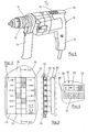
- a display field 15 of a display device 16 (indicated schematically in FIG. 3 by a dash-dotted frame) is arranged on the housing 10.
- the display panel 15 is shown enlarged in FIG. 2. It points a plurality of individual, side by side and one behind the other, spatially limited sections 17. Each row of sections 17 arranged one behind the other is assigned a scale 18 or 19 with characteristic data of the operating state of the hand drill.
- the left scale 18 in FIG. 2 contains speed information in revolutions / min and the right scale 19 in FIG. 2 contains further information about the operating state of the hand drill. "ON" means that the hand drill is switched on / off "1st GEAR" and '2.
- Each of the display panel sections 17 is selectively illuminated by a signal lamp 25 (FIG. 3).
- These signal lamps 25 are arranged directly below the display panel 15 in accordance with its configuration and are preferably designed as light-emitting diodes.
- a control circuit 26 which can be designed as a micro-computer or also as a pure coding circuit, the individual signal lamps 25 are selectively controlled and lit according to the existing operating state of the hand drill. If, for example, the hand drill is switched on, 1st gear is engaged and the drilling spindle 1 'is running clockwise at a speed of 1500 rpm, the sections 17 of the display field 15 which are marked by hatching in FIG. 2 light up. The operator can recognize the operating state by looking at the display panel 15. This is so that the user always has the display field 15 in view even during the work process arranged on the housing top 24 opposite the handle 13 and preferably embedded flush in the housing wall (FIGS. 1 and 3).
Landscapes
- Engineering & Computer Science (AREA)
- Mechanical Engineering (AREA)
- Physics & Mathematics (AREA)
- General Physics & Mathematics (AREA)
- Theoretical Computer Science (AREA)
- Sawing (AREA)
- Machine Tool Sensing Apparatuses (AREA)
- Control Of Electric Motors In General (AREA)
- Drilling And Boring (AREA)
- Portable Power Tools In General (AREA)
Applications Claiming Priority (2)
| Application Number | Priority Date | Filing Date | Title |
|---|---|---|---|
| DE19797923500U DE7923500U1 (de) | 1979-08-17 | 1979-08-17 | Elektrohandwerkzeug |
| DE7923500U | 1979-08-17 |
Publications (2)
| Publication Number | Publication Date |
|---|---|
| EP0024480A2 true EP0024480A2 (fr) | 1981-03-11 |
| EP0024480A3 EP0024480A3 (fr) | 1981-07-01 |
Family
ID=6706662
Family Applications (1)
| Application Number | Title | Priority Date | Filing Date |
|---|---|---|---|
| EP80102955A Withdrawn EP0024480A3 (fr) | 1979-08-17 | 1980-05-28 | Outil électrique à main |
Country Status (5)
| Country | Link |
|---|---|
| US (1) | US4503425A (fr) |
| EP (1) | EP0024480A3 (fr) |
| JP (1) | JPS5633286A (fr) |
| DE (1) | DE7923500U1 (fr) |
| ES (1) | ES252570Y (fr) |
Cited By (5)
| Publication number | Priority date | Publication date | Assignee | Title |
|---|---|---|---|---|
| FR2517999A1 (fr) * | 1981-12-15 | 1983-06-17 | Peugeot Outillage Elect | Perceuse portative a plusieurs vitesses |
| FR2531250A1 (fr) * | 1982-07-27 | 1984-02-03 | Kioritz Corp | Dispositif d'affichage pour machine portative a moteur |
| US5725533A (en) * | 1990-03-09 | 1998-03-10 | Nobel Biocare Ab | Torsional tightener for bone anchoring or implant elements/tools |
| EP2747948A4 (fr) * | 2011-08-26 | 2016-01-20 | Husqvarna Ab | Ensemble guide et commande |
| CN112221570A (zh) * | 2020-09-30 | 2021-01-15 | 莱芜职业技术学院 | 一种双模式电动破碎研磨机 |
Families Citing this family (7)
| Publication number | Priority date | Publication date | Assignee | Title |
|---|---|---|---|---|
| JPS58151113U (ja) * | 1982-04-02 | 1983-10-11 | 株式会社ダイゲン | パレツト停止装置 |
| JP2573629B2 (ja) * | 1987-10-30 | 1997-01-22 | 石川島播磨重工業株式会社 | ワーク整列装置 |
| JPH085136Y2 (ja) * | 1990-03-22 | 1996-02-14 | 株式会社椿本チエイン | 4方向センタリング装置 |
| US6595300B2 (en) | 2001-12-20 | 2003-07-22 | Black & Decker Inc. | Side handles on drill/drivers |
| USD487686S1 (en) | 2002-02-12 | 2004-03-23 | Black & Decker Inc. | Drill chuck, side handle, and collar arrangement |
| FR2990548B1 (fr) * | 2012-05-11 | 2016-05-27 | Nigen Steve Le | Module electrique de securite et d'information portatif |
| AU2018102160A4 (en) | 2017-07-31 | 2020-03-05 | Milwaukee Electric Tool Corporation | Rotary power tool |
Family Cites Families (9)
| Publication number | Priority date | Publication date | Assignee | Title |
|---|---|---|---|---|
| GB812287A (en) * | 1955-12-08 | 1959-04-22 | Mark Rutter | Improved means for indicating linear and angular measurements |
| US3626367A (en) * | 1969-12-22 | 1971-12-07 | Bendix Corp | Vehicle subsystem monitors |
| FR2092214A5 (fr) * | 1970-04-07 | 1971-01-21 | Arnz Friedr Aug Firma | |
| US3895517A (en) * | 1974-01-14 | 1975-07-22 | Jo Line Tools | Electronic torque wrench |
| JPS5127242A (en) * | 1974-08-30 | 1976-03-06 | Komatsu Mfg Co Ltd | Kensetsusharyo no jidoanzenkeihosochi |
| DE2442260A1 (de) * | 1974-09-04 | 1976-03-18 | Bosch Gmbh Robert | Handwerkzeugmaschine |
| US4126855A (en) * | 1975-05-12 | 1978-11-21 | Afe Industries, Inc. | Annunciator readout unit |
| US4189726A (en) * | 1977-10-27 | 1980-02-19 | Miller Richard L | Automatic orientation circuit indicator device for portable power tools and the like |
| US4254412A (en) * | 1979-06-12 | 1981-03-03 | Powell Industries, Inc. | Controller deviation indicator |
-
1979
- 1979-08-17 DE DE19797923500U patent/DE7923500U1/de not_active Expired
-
1980
- 1980-05-28 EP EP80102955A patent/EP0024480A3/fr not_active Withdrawn
- 1980-07-07 US US06/166,458 patent/US4503425A/en not_active Expired - Lifetime
- 1980-08-14 JP JP11116480A patent/JPS5633286A/ja active Pending
- 1980-08-14 ES ES1980252570U patent/ES252570Y/es not_active Expired
Cited By (7)
| Publication number | Priority date | Publication date | Assignee | Title |
|---|---|---|---|---|
| FR2517999A1 (fr) * | 1981-12-15 | 1983-06-17 | Peugeot Outillage Elect | Perceuse portative a plusieurs vitesses |
| EP0082028A1 (fr) * | 1981-12-15 | 1983-06-22 | Peugeot Outillage Electrique, Société dite: | Machine, notamment perceuse électrique |
| FR2531250A1 (fr) * | 1982-07-27 | 1984-02-03 | Kioritz Corp | Dispositif d'affichage pour machine portative a moteur |
| US5725533A (en) * | 1990-03-09 | 1998-03-10 | Nobel Biocare Ab | Torsional tightener for bone anchoring or implant elements/tools |
| EP2747948A4 (fr) * | 2011-08-26 | 2016-01-20 | Husqvarna Ab | Ensemble guide et commande |
| CN112221570A (zh) * | 2020-09-30 | 2021-01-15 | 莱芜职业技术学院 | 一种双模式电动破碎研磨机 |
| CN112221570B (zh) * | 2020-09-30 | 2021-10-29 | 莱芜职业技术学院 | 一种双模式电动破碎研磨机 |
Also Published As
| Publication number | Publication date |
|---|---|
| ES252570Y (es) | 1981-05-16 |
| DE7923500U1 (de) | 1981-02-19 |
| JPS5633286A (en) | 1981-04-03 |
| US4503425A (en) | 1985-03-05 |
| EP0024480A3 (fr) | 1981-07-01 |
| ES252570U (es) | 1980-11-16 |
Similar Documents
| Publication | Publication Date | Title |
|---|---|---|
| DE2926111C2 (fr) | ||
| DE2933355A1 (de) | Elektrohandwerkzeug | |
| DE10215736B4 (de) | Tauchoberfräse mit elektronischer Tiefeneinstellung | |
| EP2147755B1 (fr) | Foreuse, en particulier pour avant-trous, et procédé de commande de celle-ci | |
| DE3916355A1 (de) | Kraftgetriebenes werkzeug | |
| EP2915633A1 (fr) | Affichage de puissance adaptatif | |
| DE7923500U1 (de) | Elektrohandwerkzeug | |
| AT394509B (de) | Von hand steuerbare drehmaschine | |
| DE2326369A1 (de) | Vorrichtung zum einstellen einer maschine, insbesondere einer werkzeugmaschine | |
| DE3222426C1 (de) | Elektrohandwerkzeug, insbesondere Stichsäge für Heimwerker | |
| DE3136204A1 (de) | Vorrichtung zum verstellen eines rotierenden werkzeuges | |
| EP0063674A1 (fr) | Support pour tourner des rainures annulaires profondes | |
| DE3930306C2 (fr) | ||
| DE10106189B4 (de) | Werkzeugmaschine | |
| DE3812771A1 (de) | Drehzahlvorgabe fuer elektrohandwerkzeug | |
| EP1907172B1 (fr) | Outil electrique, notamment machine a fileter sans fil | |
| DE8513848U1 (de) | Fräs- oder Bohrmaschine mit einem Span- und Spritzwasserschutz in Form eines Schildes | |
| DE906398C (de) | Werkzeugmaschine fuer mehrere Arbeitsgaenge, wie Gewindepruefen, Gewindeschneiden, Bohren u. dgl. | |
| DE102015006876B4 (de) | Vorrichtung zur spanabhebenden Bearbeitung von Werkstücken | |
| DE2550333C3 (de) | Umsetzbarer Schneideinsatz | |
| DE102006032920A1 (de) | Elektrowerkzeug, insbesondere akkubetriebene Gewindeschneidmaschine | |
| EP0893199A2 (fr) | Machine-outil stationnaire, notamment machine à scie circulaire ou à fraiser | |
| DE8529200U1 (de) | Bohrmaschine, insbesondere Gewindebohrmaschine | |
| DE975910C (de) | Kommandogeraet fuer Arbeitsmaschinen mit bewegbaren Organen, insbesondere fuer Werkzeugmaschinen, Hebezeuge und Verladevorrichtungen | |
| DD140115A1 (de) | Vorrichtung zum entgraten und anfasen |
Legal Events
| Date | Code | Title | Description |
|---|---|---|---|
| PUAI | Public reference made under article 153(3) epc to a published international application that has entered the european phase |
Free format text: ORIGINAL CODE: 0009012 |
|
| 17P | Request for examination filed |
Effective date: 19800528 |
|
| AK | Designated contracting states |
Designated state(s): CH DE FR GB IT NL |
|
| PUAL | Search report despatched |
Free format text: ORIGINAL CODE: 0009013 |
|
| AK | Designated contracting states |
Designated state(s): CH DE FR GB IT NL |
|
| STAA | Information on the status of an ep patent application or granted ep patent |
Free format text: STATUS: THE APPLICATION HAS BEEN WITHDRAWN |
|
| 18W | Application withdrawn |
Withdrawal date: 19820507 |
|
| RIN1 | Information on inventor provided before grant (corrected) |
Inventor name: WESSEL, CLAUDE Inventor name: SCHAAL, GUENTER Inventor name: GERBER, HANS Inventor name: VOGEL, EBERHARD, ING.GRAD. Inventor name: STUERMER, MARIAN Inventor name: HIDVEGHY, IVAN, DIPL.-ING. |