EP0024531A2 - Dispositif d'injection de carburant pour moteurs à combustion interne - Google Patents
Dispositif d'injection de carburant pour moteurs à combustion interne Download PDFInfo
- Publication number
- EP0024531A2 EP0024531A2 EP80104180A EP80104180A EP0024531A2 EP 0024531 A2 EP0024531 A2 EP 0024531A2 EP 80104180 A EP80104180 A EP 80104180A EP 80104180 A EP80104180 A EP 80104180A EP 0024531 A2 EP0024531 A2 EP 0024531A2
- Authority
- EP
- European Patent Office
- Prior art keywords
- fuel
- needle stroke
- needle
- output
- nozzle needle
- Prior art date
- Legal status (The legal status is an assumption and is not a legal conclusion. Google has not performed a legal analysis and makes no representation as to the accuracy of the status listed.)
- Withdrawn
Links
Images
Classifications
-
- F—MECHANICAL ENGINEERING; LIGHTING; HEATING; WEAPONS; BLASTING
- F02—COMBUSTION ENGINES; HOT-GAS OR COMBUSTION-PRODUCT ENGINE PLANTS
- F02D—CONTROLLING COMBUSTION ENGINES
- F02D41/00—Electrical control of supply of combustible mixture or its constituents
- F02D41/30—Controlling fuel injection
- F02D41/32—Controlling fuel injection of the low pressure type
-
- F—MECHANICAL ENGINEERING; LIGHTING; HEATING; WEAPONS; BLASTING
- F02—COMBUSTION ENGINES; HOT-GAS OR COMBUSTION-PRODUCT ENGINE PLANTS
- F02D—CONTROLLING COMBUSTION ENGINES
- F02D41/00—Electrical control of supply of combustible mixture or its constituents
- F02D41/22—Safety or indicating devices for abnormal conditions
- F02D41/221—Safety or indicating devices for abnormal conditions relating to the failure of actuators or electrically driven elements
-
- F—MECHANICAL ENGINEERING; LIGHTING; HEATING; WEAPONS; BLASTING
- F02—COMBUSTION ENGINES; HOT-GAS OR COMBUSTION-PRODUCT ENGINE PLANTS
- F02M—SUPPLYING COMBUSTION ENGINES IN GENERAL WITH COMBUSTIBLE MIXTURES OR CONSTITUENTS THEREOF
- F02M63/00—Other fuel-injection apparatus having pertinent characteristics not provided for in groups F02M39/00 - F02M57/00 or F02M67/00; Details, component parts, or accessories of fuel-injection apparatus, not provided for in, or of interest apart from, the apparatus of groups F02M39/00 - F02M61/00 or F02M67/00; Combination of fuel pump with other devices, e.g. lubricating oil pump
- F02M63/02—Fuel-injection apparatus having several injectors fed by a common pumping element, or having several pumping elements feeding a common injector; Fuel-injection apparatus having provisions for cutting-out pumps, pumping elements, or injectors; Fuel-injection apparatus having provisions for variably interconnecting pumping elements and injectors alternatively
- F02M63/0205—Fuel-injection apparatus having several injectors fed by a common pumping element, or having several pumping elements feeding a common injector; Fuel-injection apparatus having provisions for cutting-out pumps, pumping elements, or injectors; Fuel-injection apparatus having provisions for variably interconnecting pumping elements and injectors alternatively for cutting-out pumps or injectors in case of abnormal operation of the engine or the injection apparatus, e.g. over-speed, break-down of fuel pumps or injectors ; for cutting-out pumps for stopping the engine
-
- F—MECHANICAL ENGINEERING; LIGHTING; HEATING; WEAPONS; BLASTING
- F02—COMBUSTION ENGINES; HOT-GAS OR COMBUSTION-PRODUCT ENGINE PLANTS
- F02M—SUPPLYING COMBUSTION ENGINES IN GENERAL WITH COMBUSTIBLE MIXTURES OR CONSTITUENTS THEREOF
- F02M65/00—Testing fuel-injection apparatus, e.g. testing injection timing ; Cleaning of fuel-injection apparatus
- F02M65/005—Measuring or detecting injection-valve lift, e.g. to determine injection timing
-
- F—MECHANICAL ENGINEERING; LIGHTING; HEATING; WEAPONS; BLASTING
- F02—COMBUSTION ENGINES; HOT-GAS OR COMBUSTION-PRODUCT ENGINE PLANTS
- F02B—INTERNAL-COMBUSTION PISTON ENGINES; COMBUSTION ENGINES IN GENERAL
- F02B3/00—Engines characterised by air compression and subsequent fuel addition
- F02B3/06—Engines characterised by air compression and subsequent fuel addition with compression ignition
Definitions
- the invention relates to a fuel injection device for internal combustion engines with features according to the preamble of claim 1.
- shut-off device in the fuel feed line from the fuel feed device to the fuel storage space at the nozzle needle, said shut-off device being opened and closed intermittently by a fuel supply control device.
- This device thus prevents a continuous, uncontrolled injection of fuel into the cylinder chamber in the case of a blocked nozzle needle in the open position.
- no device is provided that could signal the blocking of the nozzle needle.
- the nozzle needle stroke control device is characterized by simple and inexpensive construction and reliable monitoring of the nozzle needle stroke movements and their possible blocking both in the open position and in the closed position.
- Fuel injection devices require only minor constructive expansion measures, which practically consist only in providing a space in the valve housing coaxial to the nozzle needle, further attaching a control edge triggering an indicator signal to the nozzle needle and providing a channel in the valve housing for the laying of electrical connecting lines.
- the monitoring device connected to the control circuit for the needle stroke indicator responds with its electronic evaluation devices to all possible states of the nozzle needle movements and, in the event of the nozzle needle blocking, both in the open position and in the closed position or if it is incorrectly activated, signals a signal to a subordinate alarm signaling device - for triggering an acoustic / and / or visual alarm signal - and / or a fuel shut-off device, by means of which, in the event of the nozzle needle being blocked, the fuel feed line is shut off from the fuel delivery device to the fuel storage room of the fuel injection device.
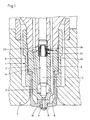
- a fuel injection device for internal combustion engines consists of an injection valve 1 with a valve housing 2, which is fastened in the cylinder head 3 of the internal combustion engine in corresponding receiving members.
- a central guide bore 4 is formed in the valve housing 2, in which a nozzle needle 5 with a shaft part 6 is guided axially movable.
- the nozzle needle 6 penetrates with its closure part 7 a fuel storage space 8, into which a fuel feed line 9 opens and from which, when the nozzle needle 5 is open, fuel can be injected into the combustion chamber via an inlet channel 10 which can be shut off by the latter and nozzle holes 11 leading away therefrom.
- the fuel feed line 9 is connected to a fuel delivery device 13 with the interposition of a fuel shut-off device 12, which consists of a fuel tank 14, a high-pressure delivery pump 15 and a constant high-pressure accumulator 16.
- the nozzle needle 5 is cyclically movable in the open and closed positions by means of an electrohydraulic control device 17, which is shown schematically in FIGS. 4 and 7 and is connected to the output amplifier 18 of a fuel supply control device 19.
- the fuel supply control device 19 is connected on the input side to a sensor 20, which is located, for example, on the crankshaft of the internal combustion engine and which delivers signals which are synchronous to the machine running speed and which are used in the control and regulating part 21 as control parameters for the exact triggering and duration of the output amplifier 18 to the electrohydraulic control device of the fuel injection device injection signals to be conducted.
- a sensor 20 which is located, for example, on the crankshaft of the internal combustion engine and which delivers signals which are synchronous to the machine running speed and which are used in the control and regulating part 21 as control parameters for the exact triggering and duration of the output amplifier 18 to the electrohydraulic control device of the fuel injection device injection signals to be conducted.
- a needle stroke indicator 22 is locked in the valve housing 2 and fixed there in a receiving bore 23 by means of radially projecting lugs 24 and installed coaxially with a shaft part 25 of the nozzle needle 5.
- the shaft part 25 of the nozzle needle 5 is opposite the shaft part 6
- the same is formed with a smaller diameter, so that at the connection point of the two shaft parts there is a control edge 26 which is used to trigger an indicator signal.
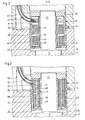
- housing 28 of the needle stroke indicator 22 is formed in two parts, a first housing inner part 29 ′ is made of brass or a correspondingly conductive alloy, while a housing outer part 30 is made of steel and has a recess 31 through which the ends are electrically and thermally insulated from outside the housing 28 are connected within a cable 33 laid in a cable duct 32 of the valve housing 2 and are connected internally to coils 34 and 35 - as shown in FIG.
- the coil 34 is a passive coil
- the coil 35 is an active coil
- the coil 36 serves as the primary coil
- the coil 37 as the passive-secondary coil
- the coil 38 as the active-secondary coil of a differential transformer.
- the coils 34 and 35 of the exemplary embodiment according to FIG. 2 are on a coil body 39
- the coils 36, 37 and 38 of the exemplary embodiment according to FIG. 3, on the other hand, are spatially separated and electrically insulated from one another on a plastic coil body 40.
- the column between art Cloth bobbin 39 and 40 and the housing 28 completely surrounding them and the respective recess 31 are completely filled with an insulating potting compound, which forms a protective layer 41.
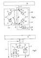
- a control circuit for the needle stroke indicator shown in FIG. 2 is shown in FIG. 5.
- the coils 34 and 35 are arranged in a half bridge 42A of a bridge circuit 42, the coil 34 serving as a passive coil being switched on in a branch 43 and the coil 35 serving as an active coil being switched on in a branch 44 lying in series with the branch 43.
- the other half-bridge 42B of the bridge circuit 42 has an ohmic or inductive or capacitive fixed-value resistor 47 or 48 in a branch 45 and in a branch 46 arranged in series therewith, both of which have the same resistance value which is matched to the resistance value of the coil 34 serving as a passive coil .
- Both half bridges 42A, 42B of the bridge circuit 42 are connected on the input side to a common input 49 and on the output side to a common output 50.
- the input 49 of the bridge circuit 42 is connected via a connecting line 51 to a carrier frequency measuring amplifier 52 which, as an output signal, supplies a voltage with a specific frequency, for example 15 volts at 5 kilohertz, to the bridge circuit 42.
- the output 50 of the bridge circuit is connected via a downstream signal amplifier 53 and its output line 54 to a signal converter 55 (FIG. 4).
- the latter is part of a monitoring device 56 and is used to convert analog voltage signals leaving the bridge circuit 42 into digital voltage signals.
- the assembly designated 57 in FIGS. 4 and 5 comprises the half bridge 42B and the signal amplifier 53 of the control circuit for the needle stroke indicator according to FIG. 2.
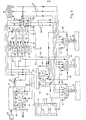
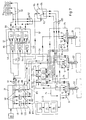
- FIG. 4 is a block diagram of an embodiment of a fuel injector with a three-cylinder Nadelhubüberwachung for Brennkraftma - illustrated machine.
- an injection valve 1 of the same design, a needle stroke indicator of the same design according to FIG. 2 and an associated control circuit shown in FIG. 5 are used for each cylinder.
- the electrohydraulic control device 17 of each fuel valve 1 is ritz p-via a connecting line 58 to the associated output 59 of the fuel supply controller 19, an output of which amplifier is in each case connected upstream of 18, is connected.
- a control channel 61 leads from each connecting line 60, which leads from an output of the control and regulating part 21 of the fuel supply control device 19 to the respective output amplifier 18, to a first input 62 of a needle stroke evaluation circuit 63, which, like the signal converter 55, also forms part of a monitoring device 56 is.
- a signal converter 55 is connected to the second input 64 of each needle stroke evaluation circuit 63 via a connecting line 65.
- an output 66 of each needle stroke evaluation circuit 63 is connected via a control channel 67 to a control input of an electronic switch 68 which is only shown schematically in the drawing and is connected in the connecting line 58 from the output 59 of the fuel supply control device 19 to the respective electrohydraulic control device 17.
- Each electronic switch 68 can be switched to an output 69 by an emergency stop signal appearing at the output 66 of the associated needle stroke evaluation circuit, so that in this case the connecting line 58 is then interrupted, so that the signal supply to the electro-hydraulic control device 17 of the relevant injection valve 1 is also interrupted by means of an alarm device 70 connected to the output 69 of the electronic switch, an optical and / or acoustic alarm signal is triggered and, in addition, a control command is given via a connecting line 71 also connected to the output 69 of the electronic switch, to the fuel shut-off device of the relevant injection valve 1 connected to it the consequence that this blocks the fuel feed line 9 from the fuel delivery device 13 to the fuel storage space 8 in the injection valve 1.
- the injection signal pending at the electrohydraulic control device 17 causes the injection valve 1 to open, provided normal functioning in accordance with the case a) described above, whereby the nozzle needle 5 moves from its closed position into its open position and the fuel under pressure in the fuel storage space 8 releases for injection into the combustion chamber.
- the stroke movement of the nozzle needle 5 compresses the field lines emerging from the active coil 35 through the control edge 26 of the nozzle needle 5, thereby generating a positive voltage pulse in the active coil 35 and detuning the bridge circuit 42 in a positive sense.
- This positive analog voltage pulse is fed at the output 50 of the bridging circuit 42 into the signal amplifier 53, amplified there and passed on via the output power 54 to the downstream signal converter 55, where it is converted into a digital signal delt and fed via the connecting line 65 and the second input 64 into the connected needle stroke evaluation circuit 63.
- the signals fed in via the two inputs 62 and 64 are now compared with one another and evaluated accordingly.
- an injection signal is present at an output of the control and regulating part 21 of the fuel supply control device 19, but one of the above-described faults b), c), d), e), f), g) or h) occurs, then appears at the output 66 of the relevant needle stroke evaluation circuit 63, due to the absence of a signal at the second input 64, an emergency stop signal, which is transmitted via the connected control channel 67 is forwarded to the downstream electronic switch 68 so that it switches over and on the one hand triggers an alarm signal at the connected alarm device 70 and on the other hand is forwarded via the connecting line 71 to the fuel shut-off device 12 of the defective or irregularly operating injection valve 1, with the result that that the normally open fuel feed line 9 is shut off from the fuel delivery device 13 to the fuel storage room 8 of the nozzle needle 5, since the alarm device 70 is assigned to a specific injection valve, the operator can also immediately locate the location of the fault and take appropriate remedial measures immediately on the spot.
- FIG. 7 shows a variant of the solution shown in FIG. 4, which can be used in particular in multi-cylinder internal combustion engines of stationary systems.
- FIG. 7 for the sake of clarity, those components and connecting lines that are identical to FIG. 4 are provided with the same reference symbols.
- a needle stroke indicator 22 with a constructive structure is corresponding in injection valve 1 with the same structure as in FIG. 4
- Fig. 3 installed.
- the coils 36, 37 and 38 of this needle stroke indicator 22 forming a differential transformer are connected to a control circuit, which is enlarged and shown in detail in FIG. 6.
- the latter has a frequency generator 72 which outputs a voltage, for example 15 volts, at outputs 73 with a specific frequency, for example 400 Hertz.
- the primary coil 36 of the needle stroke indicator 22 shown in FIG. 3 is connected to an output 73 and a demodulator 76 is connected via a line 75; the latter is part of a transmission circuit 77, which furthermore has a comparative operational amplifier 78 and an output amplifier 79.
- the comparative operational amplifier 78 has a first input 80, which is connected via a connecting line 81 to the passive secondary coil 37 of the needle stroke indicator 22 shown in FIG. 3, and a second input 82, which is connected to the active secondary via a connecting line 83 Coil 38 of the needle stroke indicator 22 shown in FIG. 3 is connected.
- the comparative operational amplifier 78 is led via a line 84 to an input 85 of the demodulator 76.
- the latter is connected on the output side via a line 86 to the input 87 of the output amplifier 79.
- This in turn has its output side * 4 connected in-the same manner as in the solution according to Fig. Via the output line 54 having a downstream transducer 55, which is also how the Nadelhubauswertscrien 63 of the monitoring device 56 identical to each of the solution shown in Fig. 4.
- each output 59 of the fuel supply control device 19 is connected to the electro-hydraulic control device 17 of an associated injection valve 1 via an interrupter switch 88 and a control line 89.
- each output 66 of a needle stroke evaluation circuit 63 is connected to an alarm device 91 via an alarm line 90 and is coupled via a control line 92 branching from the alarm line 90 to a control input 93 of an emergency stop trigger switch 94 common to all outputs.
- open emergency stop trigger switch 94 has to be monitored nozzle needles 5 two different terminal p ole 95 and 96; a control line 97 is coupled to the first connection pole 95, which leads to an input 98 of an interrupter unit 99, in which the interrupter switches 88 are combined and, if a control command is present on the control line 97, they can all be switched over together.
- a control line 100 leading to the fuel shut-off device 12 of an injection valve 1 is connected, a control command transmitted on this control line 100 causing the normally open fuel shut-off device 12 to close in the event of a fault. Since each control line 100 is connected to the same connection pole 96 of the emergency stop trigger switch 94, an emergency stop signal is transmitted simultaneously on each line 100, as a result of which all fuel supply lines 9 from the fuel delivery device 13 to the fuel storage space 8 of each injection valve are shut off by means of the fuel shutoff device 12.
- a voltage is induced in the two secondary coils 37 and 38 of the needle stroke indicator 22 according to FIG. 3 by the voltage supplied by the frequency generator 72 to the primary coil 36 via the line 74. Since the two secondary coils 37 and 38 are of identical design, the same secondary voltages are fed into the two inputs 80 and 82 of the comparative operational amplifier 78 of the transmission circuit 77 on the two connecting lines 81 and 83. Since there is no potential difference between the two secondary voltages in this case, no control signal appears on the output line 54 at the output of the comparative operational amplifier and thus also at the output of the transmission circuit 77. If an injection signal now appears at one of the outputs of the control and regulating part 21.
- this is passed on via the associated control channel 61 to the connected needle stroke evaluation circuit 63 and also via the associated control line 89 to the electro-hydraulic control device 17 of the injection valve 1 to be activated .
- the nozzle needle 5 can operate trouble-free when this signal is present, it is moved from its closed position into a stroke position; the fuel present under pressure in the fuel storage space 8 is over the nozzle bores 11 are injected into the combustion chamber; in addition, the field lines emerging from the active secondary coil 38 of the needle stroke indicator 22 according to FIG. 3 are compressed by the control edge 26 of the lifting nozzle needle 5, thereby generating a positive voltage pulse which is fed via the connecting line 83 ′ into the input 82 of the comparative operational amplifier 78 is fed.
- the nozzle needle 5 - provided that it is working without problems - is conveyed back from its open position to its closed position.
- the fuel injection process is ended, but at the same time also by moving the control edge 26 away from the needle stroke sensor 22 in the active secondary coil 38 of the same, a negative voltage pulse is indicated, so that there is a negative voltage potential between the inputs 80 and 82 of the comparative operational amplifier 78, which results in the comparative operational amplifier 78 it is evaluated that this transmits a negative pulse on the output side to the downstream demodulator 76, which signal reaches the output amplifier 79 in a demodulated manner and from there amplifies accordingly via the output line 54 to the downstream signal converter 55 of the monitoring device 56 and from there into the downstream needle stroke evaluation circuit 63 fed in and evaluated there.
- the emergency stop signal appearing at the output 66 is forwarded to the emergency stop trigger switch 94, so that the latter is closed and, as a result of this closing process, the fuel shut-off devices 12 of all the injection valves 1 are closed, so that the fuel supply to all the fuel injection valves is interrupted and also the electrohydraulic control devices 17 of all the injection valves are disconnected from the fuel supply control device 19 by opening all interrupter switches 88. Damage repair can then be carried out when the internal combustion engine is at a complete standstill.
Landscapes
- Engineering & Computer Science (AREA)
- Chemical & Material Sciences (AREA)
- Combustion & Propulsion (AREA)
- Mechanical Engineering (AREA)
- General Engineering & Computer Science (AREA)
- Fuel-Injection Apparatus (AREA)
- Electrical Control Of Air Or Fuel Supplied To Internal-Combustion Engine (AREA)
Applications Claiming Priority (2)
| Application Number | Priority Date | Filing Date | Title |
|---|---|---|---|
| DE19792934476 DE2934476A1 (de) | 1979-08-25 | 1979-08-25 | Brennstoffeinspritzvorrichtung fuer brennkraftmaschinen |
| DE2934476 | 1979-08-25 |
Publications (2)
| Publication Number | Publication Date |
|---|---|
| EP0024531A2 true EP0024531A2 (fr) | 1981-03-11 |
| EP0024531A3 EP0024531A3 (fr) | 1981-12-02 |
Family
ID=6079331
Family Applications (1)
| Application Number | Title | Priority Date | Filing Date |
|---|---|---|---|
| EP80104180A Withdrawn EP0024531A3 (fr) | 1979-08-25 | 1980-07-17 | Dispositif d'injection de carburant pour moteurs à combustion interne |
Country Status (5)
| Country | Link |
|---|---|
| EP (1) | EP0024531A3 (fr) |
| JP (1) | JPS5632048A (fr) |
| DD (1) | DD152833A1 (fr) |
| DE (1) | DE2934476A1 (fr) |
| DK (1) | DK355380A (fr) |
Cited By (11)
| Publication number | Priority date | Publication date | Assignee | Title |
|---|---|---|---|---|
| DE3124724A1 (de) * | 1980-08-11 | 1982-03-25 | VEB Wissenschaftlich-Technisches Zentrum Automobilbau Karl-Marx-Stadt, DDR 9000 Karl-Marx-Stadt | Schaltungsanordnung zum ausserbetriebsetzen von elektromagnetischen einspritzduesen |
| EP0068339A1 (fr) * | 1981-07-01 | 1983-01-05 | Robert Bosch Gmbh | Buse d'injection de carburant pour moteurs à combustion interne |
| DE3329730A1 (de) * | 1982-08-17 | 1984-02-23 | Honda Giken Kogyo K.K., Tokyo | Kraftstoffpumpen-kontrollsystem fuer brennkraftmaschinen, mit einer betriebssicherheitsfunktion fuer eine abnormitaet in kraftstoffeinspritzventilen |
| DE3444767A1 (de) * | 1983-12-09 | 1985-08-01 | Diesel Kiki Co. Ltd., Tokio/Tokyo | Einrichtung zum steuern des kraftstoffeinspritzzeitpunkts einer kraftstoffeinspritzeinrichtung |
| DE3508335A1 (de) * | 1985-03-08 | 1986-09-11 | Voest-Alpine Friedmann GmbH, Linz | Schaltungsanordnung zur erfassung der stromaenderungssignale eines an einer konstanten gleichspannung liegenden nadelhubsensors einer einspritzduese fuer brennkraftmaschinen |
| GB2177159A (en) * | 1985-06-26 | 1987-01-14 | Lucas Ind Plc | Fuel injection nozzle |
| GB2265228A (en) * | 1992-03-12 | 1993-09-22 | Toshiba Kk | Valve control system |
| EP1561934A1 (fr) * | 2004-02-03 | 2005-08-10 | Hitachi, Ltd. | Appareil de contrôle d'actuation d'un mécanisme de déplacement et une méthode de contrôle d'appareil de contrôle d'actuation |
| ES2292318A1 (es) * | 2005-09-27 | 2008-03-01 | Universidad Politecnica De Valencia | Procedimiento de deteccion de fallos en la inyeccion en motores de combustion turboalimentados. |
| CN102477927A (zh) * | 2010-11-24 | 2012-05-30 | 联创汽车电子有限公司 | 汽车发动机喷油器故障模拟和驱动电流采集电路 |
| WO2015039992A1 (fr) * | 2013-09-17 | 2015-03-26 | Robert Bosch Gmbh | Injecteur de carburant |
Families Citing this family (5)
| Publication number | Priority date | Publication date | Assignee | Title |
|---|---|---|---|---|
| DE3004424A1 (de) * | 1980-02-07 | 1981-08-13 | Robert Bosch Gmbh, 7000 Stuttgart | Kraftstoff-einspritzduesenhalter |
| JPS603460A (ja) * | 1983-06-22 | 1985-01-09 | Fujitsu Ten Ltd | 電子制御燃料噴射装置 |
| JPS61279738A (ja) * | 1985-06-06 | 1986-12-10 | Mitsubishi Heavy Ind Ltd | 内燃機関の燃料供給装置 |
| JPS62191645A (ja) * | 1986-02-18 | 1987-08-22 | Honda Motor Co Ltd | エンジンの燃料噴射制御装置 |
| DE102005007329B3 (de) * | 2005-02-17 | 2006-09-21 | Siemens Ag | Kraftstoffeinspritzventil für eine Brennkraftmaschine mit einem Düsennadel-Anschlagschalter |
Family Cites Families (7)
| Publication number | Priority date | Publication date | Assignee | Title |
|---|---|---|---|---|
| GB729431A (en) * | 1951-09-25 | 1955-05-04 | Leslie Hartridge | Apparatus and devices for testing fuel injection pumps and nozzles for internal combustion compression ignition engines |
| FR1111853A (fr) * | 1953-11-04 | 1956-03-06 | Daimler Benz Ag | Procédé pour la mesure de la course de pointeaux de gicleurs, en particulier pour gicleurs de carburant de moteurs à combustion interne |
| US3344663A (en) * | 1964-06-03 | 1967-10-03 | Allis Chalmers Mfg Co | Stroboscopic means for timing fuel injection |
| US3319613A (en) * | 1965-06-03 | 1967-05-16 | Electronic Specialty Co | Fuel injection system |
| US3385278A (en) * | 1966-10-11 | 1968-05-28 | Sentinel Distributors | Electronic actuator for an engine protective system |
| DE1751765A1 (de) * | 1968-07-25 | 1971-08-05 | Bosch Gmbh Robert | Regeleinrichtung fuer Einspritz-Brennkraftmaschinen |
| FR2267453A1 (en) * | 1974-04-09 | 1975-11-07 | Injection Mat Indl Agricole An | Safety device for diesel engine driven plant - has electro-magnetic valve shutting off fuel supply in emergency |
-
1979
- 1979-08-25 DE DE19792934476 patent/DE2934476A1/de not_active Withdrawn
-
1980
- 1980-07-17 EP EP80104180A patent/EP0024531A3/fr not_active Withdrawn
- 1980-08-18 DK DK355380A patent/DK355380A/da unknown
- 1980-08-21 DD DD22344080A patent/DD152833A1/de unknown
- 1980-08-25 JP JP11601880A patent/JPS5632048A/ja active Pending
Cited By (17)
| Publication number | Priority date | Publication date | Assignee | Title |
|---|---|---|---|---|
| DE3124724A1 (de) * | 1980-08-11 | 1982-03-25 | VEB Wissenschaftlich-Technisches Zentrum Automobilbau Karl-Marx-Stadt, DDR 9000 Karl-Marx-Stadt | Schaltungsanordnung zum ausserbetriebsetzen von elektromagnetischen einspritzduesen |
| EP0068339A1 (fr) * | 1981-07-01 | 1983-01-05 | Robert Bosch Gmbh | Buse d'injection de carburant pour moteurs à combustion interne |
| DE3329730A1 (de) * | 1982-08-17 | 1984-02-23 | Honda Giken Kogyo K.K., Tokyo | Kraftstoffpumpen-kontrollsystem fuer brennkraftmaschinen, mit einer betriebssicherheitsfunktion fuer eine abnormitaet in kraftstoffeinspritzventilen |
| DE3444767A1 (de) * | 1983-12-09 | 1985-08-01 | Diesel Kiki Co. Ltd., Tokio/Tokyo | Einrichtung zum steuern des kraftstoffeinspritzzeitpunkts einer kraftstoffeinspritzeinrichtung |
| DE3508335A1 (de) * | 1985-03-08 | 1986-09-11 | Voest-Alpine Friedmann GmbH, Linz | Schaltungsanordnung zur erfassung der stromaenderungssignale eines an einer konstanten gleichspannung liegenden nadelhubsensors einer einspritzduese fuer brennkraftmaschinen |
| US4791809A (en) * | 1985-03-08 | 1988-12-20 | Voest-Alpine Friedmann Gesselschaft M.B.H. | Circuit arrangement to detect signals indicating a change in current through a needle lift sensor of an injection nozzle in combustion engines, which is connected to a constant direct voltage supply |
| GB2177159A (en) * | 1985-06-26 | 1987-01-14 | Lucas Ind Plc | Fuel injection nozzle |
| US5316263A (en) * | 1992-03-12 | 1994-05-31 | Kabushiki Kaisha Toshiba | System for controlling electronic expansion valve provided in refrigerating machine |
| GB2265228A (en) * | 1992-03-12 | 1993-09-22 | Toshiba Kk | Valve control system |
| GB2265228B (en) * | 1992-03-12 | 1995-12-06 | Toshiba Kk | System for controlling electronic expansion valve provided in refrigerating machine |
| EP1561934A1 (fr) * | 2004-02-03 | 2005-08-10 | Hitachi, Ltd. | Appareil de contrôle d'actuation d'un mécanisme de déplacement et une méthode de contrôle d'appareil de contrôle d'actuation |
| US7623328B2 (en) | 2004-02-03 | 2009-11-24 | Hitachi, Ltd. | Driving control apparatus for motion mechanism and control method of driving control apparatus |
| ES2292318A1 (es) * | 2005-09-27 | 2008-03-01 | Universidad Politecnica De Valencia | Procedimiento de deteccion de fallos en la inyeccion en motores de combustion turboalimentados. |
| ES2292318B2 (es) * | 2005-09-27 | 2009-02-16 | Universidad Politecnica De Valencia | Procedimiento de deteccion de fallos en la inyeccion en motores de combustion turboalimentados. |
| CN102477927A (zh) * | 2010-11-24 | 2012-05-30 | 联创汽车电子有限公司 | 汽车发动机喷油器故障模拟和驱动电流采集电路 |
| CN102477927B (zh) * | 2010-11-24 | 2013-11-06 | 联创汽车电子有限公司 | 汽车发动机喷油器故障模拟和驱动电流采集电路 |
| WO2015039992A1 (fr) * | 2013-09-17 | 2015-03-26 | Robert Bosch Gmbh | Injecteur de carburant |
Also Published As
| Publication number | Publication date |
|---|---|
| JPS5632048A (en) | 1981-04-01 |
| DE2934476A1 (de) | 1981-03-26 |
| DK355380A (da) | 1981-02-26 |
| DD152833A1 (de) | 1981-12-09 |
| EP0024531A3 (fr) | 1981-12-02 |
Similar Documents
| Publication | Publication Date | Title |
|---|---|---|
| EP2041871B1 (fr) | Procédé et dispositif permettant de surveiller une distance en toute sécurité | |
| EP0205807B1 (fr) | Procédé et dispositif de commande d'une soupape électromagnétique dans un moteur | |
| DE2934476A1 (de) | Brennstoffeinspritzvorrichtung fuer brennkraftmaschinen | |
| DE2815849C2 (de) | Elektromagnetisch betätigte Gaswechselventile für Kolbenmaschinen | |
| DE2254250C3 (de) | Drehzahlbegrenzungseinrichtung fur eine Turbine | |
| DE1904880B2 (de) | Elektromagnetische Betätigungsvorrichtung | |
| DE3508608C2 (fr) | ||
| DE3347459C2 (fr) | ||
| DE4142996A1 (de) | Verfahren zum messen der mechanischen bewegung eines magnetventilankers, insbesondere von elektrisch gesteuerten einspritzanlagen | |
| DE2235642A1 (de) | Einrichtung zur kontrolle von elektrischen verbrauchern in kraftfahrzeugen | |
| WO1998024014A1 (fr) | Procede et dispositif d'examen et/ou de reglage de soupapes | |
| DE4207275A1 (de) | Elektromagnetischer stellantrieb | |
| DE2925581C2 (de) | Einrichtung zur berührungslosen Schaltstellungsüberwachung an hydraulischen oder pneumatischen Ventilen | |
| DE2518626C3 (de) | Druckmittelversorgungseinrichtung für hydraulische Hilfskraftlenkungen von Fahrzeugen | |
| EP1313936B1 (fr) | Procede et dispositif de commande d'un moteur a combustion interne | |
| DE3143967C2 (fr) | ||
| EP1061238B1 (fr) | Méthode de surveillance de l'opération d'un moteur à pistons avec des soupapes d'échange de gaz variables | |
| DE69614238T2 (de) | Zweihand-Steuerschaltung für Pressen | |
| DE2237746A1 (de) | Einspritzventil fuer dieselbrennkraftmaschinen | |
| EP0889223B1 (fr) | Procédé et dispositif pour détecter l'instant de commutation d'une électrovalve | |
| EP0069111A1 (fr) | Dispositif de réglage pour commander l'instant d'injection et/ou le débit d'une pompe d'injection de combustible pour moteurs à combustion interne | |
| EP0258214B1 (fr) | Agencement de controle de consommateurs d'electricite dans des vehicules a moteur | |
| WO2002006104A1 (fr) | Dispositif de controle mecanique et electrique de systeme de reglage d'appareil de commande d'aiguillage | |
| WO1985001083A1 (fr) | Dispositif de dosage du carburant pour un moteur a combustion interne | |
| CH657184A5 (de) | Einrichtung zum regeln einer turbine und zum schuetzen derselben vor einer ueberdrehzahl und verfahren zum pruefen der schnellschlussfunktion dieser einrichtung. |
Legal Events
| Date | Code | Title | Description |
|---|---|---|---|
| PUAI | Public reference made under article 153(3) epc to a published international application that has entered the european phase |
Free format text: ORIGINAL CODE: 0009012 |
|
| AK | Designated contracting states |
Designated state(s): DE FR IT NL |
|
| PUAL | Search report despatched |
Free format text: ORIGINAL CODE: 0009013 |
|
| 17P | Request for examination filed |
Effective date: 19810806 |
|
| STAA | Information on the status of an ep patent application or granted ep patent |
Free format text: STATUS: THE APPLICATION HAS BEEN WITHDRAWN |
|
| AK | Designated contracting states |
Designated state(s): DE FR IT NL |
|
| 18W | Application withdrawn |
Withdrawal date: 19811117 |
|
| RIN1 | Information on inventor provided before grant (corrected) |
Inventor name: BIRKNER, GEORG Inventor name: KATTENBUSCH, GUENTER Inventor name: KOSCHEL, KURT |