EP0025627B1 - Procédé et dispositif pour broyer ou râper des tubercules, racines, fruits, semences et produits agricoles similaires pour les réduire à l'état de pulpe - Google Patents
Procédé et dispositif pour broyer ou râper des tubercules, racines, fruits, semences et produits agricoles similaires pour les réduire à l'état de pulpe Download PDFInfo
- Publication number
- EP0025627B1 EP0025627B1 EP80200841A EP80200841A EP0025627B1 EP 0025627 B1 EP0025627 B1 EP 0025627B1 EP 80200841 A EP80200841 A EP 80200841A EP 80200841 A EP80200841 A EP 80200841A EP 0025627 B1 EP0025627 B1 EP 0025627B1
- Authority
- EP
- European Patent Office
- Prior art keywords
- rasping
- grinding
- fluid
- feeding
- products
- Prior art date
- Legal status (The legal status is an assumption and is not a legal conclusion. Google has not performed a legal analysis and makes no representation as to the accuracy of the status listed.)
- Expired
Links
- 238000000034 method Methods 0.000 title claims abstract description 23
- 235000013399 edible fruits Nutrition 0.000 title claims abstract description 4
- QVGXLLKOCUKJST-UHFFFAOYSA-N atomic oxygen Chemical compound [O] QVGXLLKOCUKJST-UHFFFAOYSA-N 0.000 claims abstract description 12
- 239000001301 oxygen Substances 0.000 claims abstract description 12
- 229910052760 oxygen Inorganic materials 0.000 claims abstract description 12
- 239000007789 gas Substances 0.000 claims description 32
- XLYOFNOQVPJJNP-UHFFFAOYSA-N water Substances O XLYOFNOQVPJJNP-UHFFFAOYSA-N 0.000 claims description 27
- 239000012530 fluid Substances 0.000 claims description 23
- 239000011261 inert gas Substances 0.000 claims description 7
- 239000000203 mixture Substances 0.000 claims description 7
- 238000000926 separation method Methods 0.000 claims description 5
- 239000007788 liquid Substances 0.000 claims description 4
- 230000002706 hydrostatic effect Effects 0.000 claims description 3
- 238000012544 monitoring process Methods 0.000 claims description 3
- 238000005086 pumping Methods 0.000 claims description 3
- 239000007787 solid Substances 0.000 claims 1
- 239000000047 product Substances 0.000 description 37
- IJGRMHOSHXDMSA-UHFFFAOYSA-N Atomic nitrogen Chemical compound N#N IJGRMHOSHXDMSA-UHFFFAOYSA-N 0.000 description 6
- 230000001681 protective effect Effects 0.000 description 5
- 235000002595 Solanum tuberosum Nutrition 0.000 description 3
- 244000061456 Solanum tuberosum Species 0.000 description 3
- 229910052757 nitrogen Inorganic materials 0.000 description 3
- 238000007254 oxidation reaction Methods 0.000 description 3
- 235000012015 potatoes Nutrition 0.000 description 3
- 238000011282 treatment Methods 0.000 description 3
- 229920002472 Starch Polymers 0.000 description 2
- 230000000694 effects Effects 0.000 description 2
- 238000005265 energy consumption Methods 0.000 description 2
- 235000013305 food Nutrition 0.000 description 2
- 230000003647 oxidation Effects 0.000 description 2
- 230000000630 rising effect Effects 0.000 description 2
- 235000019698 starch Nutrition 0.000 description 2
- 239000008107 starch Substances 0.000 description 2
- 238000010521 absorption reaction Methods 0.000 description 1
- 239000003638 chemical reducing agent Substances 0.000 description 1
- 238000001704 evaporation Methods 0.000 description 1
- 238000012423 maintenance Methods 0.000 description 1
- 239000003607 modifier Substances 0.000 description 1
- 230000035515 penetration Effects 0.000 description 1
- 102000004169 proteins and genes Human genes 0.000 description 1
- 108090000623 proteins and genes Proteins 0.000 description 1
- 239000000126 substance Substances 0.000 description 1
- LSNNMFCWUKXFEE-UHFFFAOYSA-L sulfite Chemical class [O-]S([O-])=O LSNNMFCWUKXFEE-UHFFFAOYSA-L 0.000 description 1
- 239000013589 supplement Substances 0.000 description 1
- 238000005406 washing Methods 0.000 description 1
Images
Classifications
-
- C—CHEMISTRY; METALLURGY
- C08—ORGANIC MACROMOLECULAR COMPOUNDS; THEIR PREPARATION OR CHEMICAL WORKING-UP; COMPOSITIONS BASED THEREON
- C08B—POLYSACCHARIDES; DERIVATIVES THEREOF
- C08B30/00—Preparation of starch, degraded or non-chemically modified starch, amylose, or amylopectin
- C08B30/02—Preparatory treatment, e.g. crushing of raw materials or steeping process
Definitions
- the invention relates to a method of grinding or rasping to pulp tubers, roots, fruit, seeds and, similar agricultural produce.
- Such a method is generally known and is employed in starch industry, for example, for rasping potatoes in order to extract therefrom starch, protein and various other products.
- a method is generally known and is employed in starch industry, for example, for rasping potatoes in order to extract therefrom starch, protein and various other products.
- oxyda- tion and hence discolouring of various products occur, which discolouring is undesirable in the final products.
- reducing agents such as S0 2 and sulfites in an early stage of the process.
- US-A-2 583 697 describes a process of comminuting food products.
- the food products are treated with liquified nitrogen whereby the temperature of the products fall far below 0°C. In this state the products are very brittle and can easily be ground.
- An extra advantage of this process is, that by saturation with evaporating nitrogen, no oxygen can get access to the products and therefore no oxidation will occur.
- vast amounts of liquid nitrogen are necessary which makes the product dear.
- the invention provides a method in which said disadvantages are avoided in that the products, between which the spaces are not filled with liquid, are ground or rasped in environments free of oxygen or of poor oxygen content.
- the products are ground or rasped in vacuo, which has the additional advantage that the volume of the resultant pulp is limited, since the absorption of gas is avoided. Therefore, the bulk of the system for further processing the pulp may be reduced. Since the presence of gases in the pulp is inconvenient in various treatments, it is an additional advantage that no supplementary treatment or apparatus is required for eliminating such disadvantages.
- the vacuum method may be replaced by grinding or rasping in an inert gas atmosphere.
- an inert gas atmosphere may be used in many cases, from which oxygen is removed.
- the invention furthermore relates to a device for carrying out the method described above, said device comprising a grinding or rasping equipment, a feeding device for the products to be ground or rasped and a delivery device for the ground pulp.
- a device which is known per se, is modified for carrying out the method in accordance with the invention in a manner such that the grinding or rasping equipment comprises a gastight housing, through the wall of which the conduits of the feeding and delivery devices are passed and that the feeding device is provided with a sluice preventing oxygen from entering.
- the housing is preferably resistant to internal vacuum
- the feeding and delivery devices are produced with vacuum sluices and the housing is provided with a vacuum connection.
- the oxygen- retaining sluice in a preferred embodiment is formed by a fluid trap having transport means for passing products to be ground across it to above the grinding or rasping device.
- a fluid trap having transport means for passing products to be ground across it to above the grinding or rasping device.
- the fluid trap forming a vacuum sluice and at the same time an oxygen-barring member is preferably provided with a water-filled riser of about 10 ml high.
- This riser constitutes a part of the feeding device for the products to be ground or rasped.
- This embodiment is interesting, since in many cases the products to be ground are conveyed by an elevator from the washing device to the grinding or rasping device arranged at a high level in the factory.
- the feeding device comprises a U-shaped tube having a short limb and a long limb, the long limb corresponding to the hydrostatic height opening out in a separation chamber having a sloping sieve bottom allowing only fluid to pass and communicating with an outlet conduit leading to the grinding or rasping device, beneath which chamber is arranged a fluid collecting bottom provided with a down-comer including a pump, said down-comer opening out in the open, short limb of the U-shaped tube.
- This short limb of the U-shaped tube serves to receive the products to be ground, for which purpose a feeding funnel may be arranged above the open end of the short limb.
- the down-comer preferably opens out near the open end of the short limb.
- a scanner which is adjustable in a direction of height for monitoring the fluid and which is coupled with a closing member in a supply conduit opening out in the fluid trap.
- the fluid supply conduit preferably opens out near the open end of the short limb.
- the housing is provided with a supply conduit for said gas.
- This supply conduit may be connected either with an inert or reducing gas producing device or with a stock thereof or with a gas separator arranged in the delivery device.
- the latter form is preferred, since in this case the volume of the pulp to be processed as well as the consumption of gas are reduced because the gas is recycled.
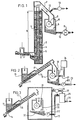
- the rasping device 6 comprises a gastight housing 8 resistant to internal vacuum, in which a rasp rotor 9 is adapted to rotate. With the bottom side of the housing communicates a delivery device for the rasped pulp comprising a conduit 10 and a pump 11 included therein, which can conduct away the pulp against the atmospheric pressure and serves, in addition, as a hermetic seal.
- the riser 3, the closed chute 7 and the housing 8 constitute a system closed from the atmosphere and having a hermetic closure 12 in the part not filled with water or pulp, with which is connected an exhaust pump 13.
- the housing 8, the chute 7 and the riser 3 are exhausted by means of the exhaust pump 13, the water thus rising in the riser 3 to a height h of about 10 m.
- the products to be rasped can be supplied through the conduit 1, the elevator and the chute 7 for being rasped in an oxygen-free manner into a gas-free pulp not exposed to oxidation. This pulp is conducted away by means of the pump 11 for being further processed.
- Fig. 2 shows a device for rasping agricultural products in a protective gas atmosphere.
- the products are supplied to an oxygen-barring sluice in the form of a water trap 14 constituted by a reservoir 15, which communicates on the bottom side with an upwardly inclined pipe 16, in which a worm conveyor 17 is arranged with an amount of clearance.
- the worm conveyor 17 can conduct the products from the water-filled reservoir 15 upwards through the pipe 1 6 without carrying along an appreciable amount of water.
- the worm conveyor 17 terminates at a connection of the pipe 16 with a downwardly extending feeding pipe 18 leading to a rasping device 19, whose housing 20 is closed in a gastight manner, apart from the supply pipe 18, a gas supply conduit 21 and a pulp delivery conduit 23 including a pump 22.
- the penetration of oxygen is prevented by the water trap 14 in the feeding device and the pump 22 in the delivery device.
- a gas separator 25 can be arranged in the delivery conduit 23 downstream the pump.
- This embodiment is illustrated in fig. 3.
- the pulp from which the gas separator has extracted the gas is conducted away through a conduit 26 and the gas is fed back through a return conduit 27 with the blower 28 to the rasping device so that the protective gas is recycled.
- Fig. 3 shows moreover, a conventional rasping device 29.
- a conventional rasping device 29 In order to adapt the same to the method in accordance with the invention it is arranged in a separate gastight housing 30.
- In this housing opens out a feeding device 14 to 17 as described with reference to fig. 2 and the products to be rasped out are shed into a filling funnel 31 of the rasping equipment 29.
- the pulp formed by the rasping device is conducted away from a pulp collecting trough 32 via the outlet conduit 23 including a pump 22.
- grinding devices such as hammer mills, beater mills, tine-disc crushers may be used.
- the choice thereof will usually depend upon the products to be worked and the aftertreatment thereof.
- a hermetic closing member may be used as a variant comprising a riser of 10 m high, in the bottom end of which opens out a feeding conduit for the products to be ground or rasped.
- the riser is provided with a conventional pump for pumping up a mixture of water and products to be ground, for example, potatoes so that at the top of the riser the mixture slightly exceeds the manometric height of the rise.
- the mixture flows over into an outlet gutter with a perforated bottom.
- the outlet gutter leads to the grinding or rasping device and beneath the perforated bottom a collecting trough is arranged and connected on the bottom side with a delivery conduit leading downwards to the bottom side of the riser. In this way the water is pumped around.
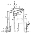
- Fig. 4 is a schematic, vertical sectional view of a preferred vacuum rasping device.
- a U-shaped pipe 33 having a short limb 34 and a long limb 35 is filled with water;
- the short limb 34 which is open at the top end and which is provided with a feeding funnel 36, are introduced the products to be ground. Since the vertical distance h' between the water level in the short limb and the top side of the long limb is smaller than the hydrostatic height, which corresponds to the vacuum in the rasping device, the water in the U-shaped pipe will flow towards the top end of the long limb 34 and carry along the products to be rasped.
- the mixture of products to be ground and water flows from the long limb 35 into a separation chamber 36 having an inclined sieve bottorr 37 allowing only water to pass, which communicates with a delivery conduit 38 for passing the products to the vacuum grinding or rasping device 19.
- the products are ground or rasped to a pump, which is conducted away through an outlet conduit 23 including a pump 22.
- the water of the mixture flows through the sieve bottom 37 into a collecting trough 39 having a down-comer 40 in which a pump 41, for example, a centrifugal pump is arranged for pumping the fluid back to the short limb 34 of the U-shaped pipe 33.
- a pump 41 for example, a centrifugal pump is arranged for pumping the fluid back to the short limb 34 of the U-shaped pipe 33.
- a scanner 42 which is adjustable in a direction of height, for example, a float for monitoring the fluid level, said scanner being coupled with a closing member 43 in a fluid feeding conduit 44 opening out in the short limb 34.
Landscapes
- Chemical & Material Sciences (AREA)
- Chemical Kinetics & Catalysis (AREA)
- Engineering & Computer Science (AREA)
- Biochemistry (AREA)
- Materials Engineering (AREA)
- Health & Medical Sciences (AREA)
- Life Sciences & Earth Sciences (AREA)
- Medicinal Chemistry (AREA)
- Polymers & Plastics (AREA)
- Organic Chemistry (AREA)
- Pretreatment Of Seeds And Plants (AREA)
- Apparatuses For Bulk Treatment Of Fruits And Vegetables And Apparatuses For Preparing Feeds (AREA)
- Paper (AREA)
- Preparation Of Fruits And Vegetables (AREA)
Claims (19)
Priority Applications (1)
| Application Number | Priority Date | Filing Date | Title |
|---|---|---|---|
| AT80200841T ATE4464T1 (de) | 1979-09-10 | 1980-09-08 | Verfahren und vorrichtung zum mahlen oder reiben von knollen, wurzeln, obst, samen und gleichartiger ackerbauprodukte zu pulpe. |
Applications Claiming Priority (2)
| Application Number | Priority Date | Filing Date | Title |
|---|---|---|---|
| NL7906735 | 1979-09-10 | ||
| NL7906735A NL7906735A (nl) | 1979-06-27 | 1979-09-10 | Werkwijze en inrichting voor het tot een brij malen of raspen van knollen, wortelen, vruchten, zaden en dergelijke landbouwprodukten. |
Publications (2)
| Publication Number | Publication Date |
|---|---|
| EP0025627A1 EP0025627A1 (fr) | 1981-03-25 |
| EP0025627B1 true EP0025627B1 (fr) | 1983-08-17 |
Family
ID=19833816
Family Applications (1)
| Application Number | Title | Priority Date | Filing Date |
|---|---|---|---|
| EP80200841A Expired EP0025627B1 (fr) | 1979-09-10 | 1980-09-08 | Procédé et dispositif pour broyer ou râper des tubercules, racines, fruits, semences et produits agricoles similaires pour les réduire à l'état de pulpe |
Country Status (4)
| Country | Link |
|---|---|
| EP (1) | EP0025627B1 (fr) |
| AT (1) | ATE4464T1 (fr) |
| DE (1) | DE3064585D1 (fr) |
| DK (1) | DK150798C (fr) |
Families Citing this family (3)
| Publication number | Priority date | Publication date | Assignee | Title |
|---|---|---|---|---|
| JPS5934344B2 (ja) * | 1982-04-28 | 1984-08-22 | ニフオバ・ベ−・ヴエ− | 農産物の処理方法及び装置 |
| IT1187164B (it) * | 1985-04-24 | 1987-12-16 | Rossi & Catelli Spa | Procedimento ed impianto per ridurre in succo e/o pasta prodotti alimentari |
| CN115069406B (zh) * | 2022-06-01 | 2024-07-26 | 杭州中泽生物科技有限公司 | 一种水稻种子筛选系统及筛选方法 |
Family Cites Families (2)
| Publication number | Priority date | Publication date | Assignee | Title |
|---|---|---|---|---|
| US2583697A (en) * | 1950-06-05 | 1952-01-29 | Jr John L Hendry | Process of comminuting food products |
| US3399838A (en) * | 1966-05-13 | 1968-09-03 | Nat Oats Company | Reduction of cereal grains to flour |
-
1980
- 1980-09-08 EP EP80200841A patent/EP0025627B1/fr not_active Expired
- 1980-09-08 AT AT80200841T patent/ATE4464T1/de not_active IP Right Cessation
- 1980-09-08 DE DE8080200841T patent/DE3064585D1/de not_active Expired
- 1980-09-09 DK DK382680A patent/DK150798C/da not_active IP Right Cessation
Also Published As
| Publication number | Publication date |
|---|---|
| EP0025627A1 (fr) | 1981-03-25 |
| DE3064585D1 (en) | 1983-09-22 |
| DK150798B (da) | 1987-06-22 |
| ATE4464T1 (de) | 1983-09-15 |
| DK382680A (da) | 1981-03-11 |
| DK150798C (da) | 1988-02-01 |
Similar Documents
| Publication | Publication Date | Title |
|---|---|---|
| FI58655C (fi) | Apparatur foer framstaellning av socker av hemicellulosahaltiga raoaemnen i synnerhet foer framstaellning av xylos av xylanhaltiga raoaemnen | |
| CA2409861A1 (fr) | Dispositif et procede de friture de produits | |
| US4898189A (en) | Method of and apparatus for treating uncured tobacco | |
| JP2001503112A (ja) | 細砕された繊維性材料を供給するための方法およびシステム | |
| US2858213A (en) | Wood chip digestion | |
| US3714887A (en) | Apparatus for crushing fruit in an inert gas | |
| CN102083331B (zh) | 电穿孔处理甜菜丝的方法及其实现设备 | |
| EP0025627B1 (fr) | Procédé et dispositif pour broyer ou râper des tubercules, racines, fruits, semences et produits agricoles similaires pour les réduire à l'état de pulpe | |
| US2225459A (en) | Method of separating the heart and sap wood constituents of coniferous woods | |
| NO149761B (no) | Filtreringsanordning med en kontinuerlig under undertrykk og overtrykk arbeidende filterinnretning | |
| EP0232000A1 (fr) | Méthode et dispositif pour pomper un liquide | |
| US2809111A (en) | Apparatus for wood chip digestion | |
| EP0092852A1 (fr) | Procédé et dispositif pour la transformation de produits agricoles | |
| EP0265678B1 (fr) | Elaboration de produits biologiques | |
| JPH0147227B2 (fr) | ||
| US2800459A (en) | Removal of froth | |
| NL7906735A (nl) | Werkwijze en inrichting voor het tot een brij malen of raspen van knollen, wortelen, vruchten, zaden en dergelijke landbouwprodukten. | |
| CS277395B6 (en) | Device for treating agricultural products by disintegration, crushing or grating | |
| US3595696A (en) | Corn steeping process and apparatus | |
| US2121633A (en) | Method of treating carbon black | |
| US2784841A (en) | Hydraulic classification of solids | |
| US2518814A (en) | Method and means for the separation of fibers suspended in a liquid | |
| NO832933L (no) | Fremgangsmaate, samt anordning for behandling av jordbruksprodukter | |
| US20030102093A1 (en) | Processes and systems for handling knots in a chemical pulping process | |
| KR100434624B1 (ko) | 음식물 쓰레기 분해 처리 장치 |
Legal Events
| Date | Code | Title | Description |
|---|---|---|---|
| PUAI | Public reference made under article 153(3) epc to a published international application that has entered the european phase |
Free format text: ORIGINAL CODE: 0009012 |
|
| AK | Designated contracting states |
Designated state(s): AT DE FR NL SE |
|
| 17P | Request for examination filed |
Effective date: 19810923 |
|
| GRAA | (expected) grant |
Free format text: ORIGINAL CODE: 0009210 |
|
| AK | Designated contracting states |
Designated state(s): AT DE FR NL SE |
|
| REF | Corresponds to: |
Ref document number: 4464 Country of ref document: AT Date of ref document: 19830915 Kind code of ref document: T |
|
| REF | Corresponds to: |
Ref document number: 3064585 Country of ref document: DE Date of ref document: 19830922 |
|
| ET | Fr: translation filed | ||
| PLBE | No opposition filed within time limit |
Free format text: ORIGINAL CODE: 0009261 |
|
| STAA | Information on the status of an ep patent application or granted ep patent |
Free format text: STATUS: NO OPPOSITION FILED WITHIN TIME LIMIT |
|
| 26N | No opposition filed | ||
| PGFP | Annual fee paid to national office [announced via postgrant information from national office to epo] |
Ref country code: AT Payment date: 19930928 Year of fee payment: 14 |
|
| PGFP | Annual fee paid to national office [announced via postgrant information from national office to epo] |
Ref country code: FR Payment date: 19930929 Year of fee payment: 14 |
|
| PGFP | Annual fee paid to national office [announced via postgrant information from national office to epo] |
Ref country code: SE Payment date: 19930930 Year of fee payment: 14 Ref country code: NL Payment date: 19930930 Year of fee payment: 14 |
|
| PGFP | Annual fee paid to national office [announced via postgrant information from national office to epo] |
Ref country code: DE Payment date: 19931130 Year of fee payment: 14 |
|
| PG25 | Lapsed in a contracting state [announced via postgrant information from national office to epo] |
Ref country code: AT Effective date: 19940908 |
|
| PG25 | Lapsed in a contracting state [announced via postgrant information from national office to epo] |
Ref country code: SE Effective date: 19940909 |
|
| EAL | Se: european patent in force in sweden |
Ref document number: 80200841.7 |
|
| PG25 | Lapsed in a contracting state [announced via postgrant information from national office to epo] |
Ref country code: NL Effective date: 19950401 |
|
| NLV4 | Nl: lapsed or anulled due to non-payment of the annual fee | ||
| PG25 | Lapsed in a contracting state [announced via postgrant information from national office to epo] |
Ref country code: FR Effective date: 19950531 |
|
| PG25 | Lapsed in a contracting state [announced via postgrant information from national office to epo] |
Ref country code: DE Effective date: 19950601 |
|
| EUG | Se: european patent has lapsed |
Ref document number: 80200841.7 |
|
| REG | Reference to a national code |
Ref country code: FR Ref legal event code: ST |