EP0028103B1 - Analyseur de spectre - Google Patents
Analyseur de spectre Download PDFInfo
- Publication number
- EP0028103B1 EP0028103B1 EP80303655A EP80303655A EP0028103B1 EP 0028103 B1 EP0028103 B1 EP 0028103B1 EP 80303655 A EP80303655 A EP 80303655A EP 80303655 A EP80303655 A EP 80303655A EP 0028103 B1 EP0028103 B1 EP 0028103B1
- Authority
- EP
- European Patent Office
- Prior art keywords
- circuits
- outputs
- square
- subtraction
- accumulators
- Prior art date
- Legal status (The legal status is an assumption and is not a legal conclusion. Google has not performed a legal analysis and makes no representation as to the accuracy of the status listed.)
- Expired
Links
Images


Classifications
-
- G—PHYSICS
- G01—MEASURING; TESTING
- G01R—MEASURING ELECTRIC VARIABLES; MEASURING MAGNETIC VARIABLES
- G01R23/00—Arrangements for measuring frequencies; Arrangements for analysing frequency spectra
- G01R23/16—Spectrum analysis; Fourier analysis
- G01R23/165—Spectrum analysis; Fourier analysis using filters
- G01R23/167—Spectrum analysis; Fourier analysis using filters with digital filters
-
- G—PHYSICS
- G10—MUSICAL INSTRUMENTS; ACOUSTICS
- G10L—SPEECH ANALYSIS TECHNIQUES OR SPEECH SYNTHESIS; SPEECH RECOGNITION; SPEECH OR VOICE PROCESSING TECHNIQUES; SPEECH OR AUDIO CODING OR DECODING
- G10L19/00—Speech or audio signals analysis-synthesis techniques for redundancy reduction, e.g. in vocoders; Coding or decoding of speech or audio signals, using source filter models or psychoacoustic analysis
- G10L19/02—Speech or audio signals analysis-synthesis techniques for redundancy reduction, e.g. in vocoders; Coding or decoding of speech or audio signals, using source filter models or psychoacoustic analysis using spectral analysis, e.g. transform vocoders or subband vocoders
Definitions
- This invention relates to a spectrum analyser.
- the voice frequency band is divided into several channels in order to obtain such a power distribution.
- Band-pass filters corresponding to the respective channels are provided, and the output power of each band-pass filter is rectified and smoothed with a specified time interval, thereby voice analysis data can be obtained.
- Bandpass filters equal in number to the channels are required, and thus expensive band-pass filters of the same number as the number of voice analysis channels are required for a voice recognition unit. Generally, ten or more band-pass filters are required.
- the disclosed high-pass filter spectrum analyzer has a plurality of high-pass analog filters. The digital process was ruled out because conversion to digital form made the filter process very slow.
- the disclosed filter also has a plurality of squaring circuits, one connected to receive the signal to be analysed via a rectifier the others connected via respective rectifiers for receiving the outputs of respective filters.
- a plurality of integrators are connected respectively to receive the outputs of the squaring circuits.
- a plurality of summers are connected each to receive the output of one integrator and, via an inverter, the output of another integrator. The summers deliver the outputs of the analyzer.
- a sprectrum analyzer having a plurality of low (or high) pass filters connected for receiving in parallel a signal to be analysed, a plurality of square circuits connected to respective filters, a plurality of accumulators, and a plurality of subtraction circuits characterised in that the plurality of subtraction circuits are connected for receiving signals directly from the outputs of respective pairs of square circuits each for deriving the difference between the signals from the outputs of the square circuits of the pair concerned, each such pair of square circuits being connected respectively to one filter and to another filter of the next highest, or next lowest, cut-off frequency, and in that the plurality of accumulators are connected to respective subtraction circuits to receive outputs therefrom.
- pairs differing in only one member are different pairs.
- An embodiment of this invention provides for the realization of a band-pass filter by a parallel connection of a couple of digital low- (or high-) pass filters, and utilizes the fact that data actually required for spectrum analyses (e.g. voice spectrum analysis) is the power obtained from each channel.
- spectrum analyses e.g. voice spectrum analysis
- An embodiment of this invention comprises digital/analog converters, digital low- (or high-) pass filters, square circuits, subtraction circuits and accumulators.
- n band-pass filters one for each channel, required when the frequency bands of the n channels are continuous (i.e. where the upper limit of one channel is substantially contiguous with the lower limit of a next channel), are effectively realized by means of n + 1 digital low- (or high-) pass filters.
- a band-pass filter In general, to realize a band-pass filter the number of orders (orders of the transfer function of a filter) is almost doubled as compared with that of a digital low- (or high-) pass filter having a similar frequency cut-off characteristic.
- a band-pass filter can be realized with the number of orders which is about half the existing requirement. This is because one digital low-(or high-) pass filter can be used in common to two adjacent frequency bands. Therefore, the number of multiplications required can be reduced by half as compared with that of an existing method wherein a band-pass filter is directly provided. Thereby, an economical improvement can be attained through a specific cost reduction.
- 1 is an input terminal; 2-1, 2-2, 2-3 to 2-n are band-pass filters for respective channels which correspond to continuous voice frequencies. That is to say, the respective channels deal with respective frequency bands which are continuous from one channel to the next. The upper limit of the frequency band of one channel is contiguous with the lower limit of the frequency band of the next channel.
- 3-1 to 3-n are full-wave rectifiers; 4-1 to 4-n are integral circuits; 5-1, 5-2, 5-3 to 5-n are output terminals from which spectrum analysis outputs for each voice channel are delivered.
- a voice signal delivered to the input terminal 1 is divided into voice channel frequency bands by the respective band-pass filters 2-1, 2-2, 2-3 to 2-n.
- the frequencies of each channel are doubled by the full-wave rectifiers 3-1 to 3-n and the outputs of such rectifiers are integrated respectively by the integral circuits 4-1 to 4-n.
- mean (power) values of bands of the spectrum are output from output terminals 5-1, 5-2, 5-3 to 5-n.
- a spectrum analyzer is formed.
- the prior art analyzer requires a band-pass filter for each channel, for the purpose of spectrum analysis of each channel.
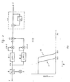
- Fig. 2(a) 1 is an input terminal (as in Fig. 1); 5 is an output terminal; 6 is an analog/digital converter (hereinafter referred to as A/D converter); 7 is a clock pulse source for use in sampling an input signal from the input terminal; 8 ⁇ 1, 8 ⁇ 2 are digital low-pass filters (cut-off frequencies, f c1 , f c2 respectively); 23-1, 23-2 are square circuits; 24 is a subtraction circuit; 25 is an accumulator which accumulates, for example, the outputs of subtraction circuit 24 over a time interval of 10 msec and then outputs the accumulated memory value simultaneously with clearing of the accumulator by a clear pulse; and Z -1 is a delay circuit.
- A/D converter analog/digital converter
- 7 is a clock pulse source for use in sampling an input signal from the input terminal
- 8 ⁇ 1, 8 ⁇ 2 are digital low-pass filters (cut-off frequencies, f c1 , f c2 respectively)
- 23-1, 23-2 are
- curves 10 and 11 illustrate the transmission characteristics of the digital low-pass filters 8-1, 8-2 of Figure 2(a) respectively.
- the horizontal axis indicates frequency f
- the vertical axis indicates transmission gain
- f c1 , f C2 respectively indicate the cut-off frequencies of the digital low-pass filters 8 ⁇ 1, 8 ⁇ 2
- f s is the sampling frequency of source 7.
- the voice signal input delivered to the input terminal 1 is sampled in response to sampling pulses sent from the sampling pulse source 7 in the A/D converter 6.
- a sampled digital signal series is input to digital low-pass filter 8-1 having the transmission characteristic 10 as shown in Figure 2(b), which provides an output y1 (n).
- the sampled signal series output from the A/D converter 6 is also input to the digital low-pass filter 8-2 having the transmission characteristic 11, providing an output y2(n).
- the respective outputs of the digital low-pass filters 8-1, 8-2 are squared by the square circuits 23 ⁇ 1, 23 ⁇ 2 and outputs y1(n) 2 , y2(n) 2 are obtained.
- the outputs of square circuits 23 ⁇ 1, 23-2 are subject to subtraction in the subtraction circuit 24.
- the result is input to the accumulator 25.
- the values of data fed thereto are memorised and accumulated in the accumulator 25 (which is a complete integral circuit) over a period of 10 msec and then output from the accumulator. Simultaneously, the accumulator memory value is cleared.
- the output value from the accumulator is proportional to the signal energy within the frequency band f c1 ⁇ f c2 and this accumulated value is output as voice spectrum analysis information.
- the transfer function of a band-pass filter is taken to be H(z) and the transfer functions of the digital low-pass filters 8 ⁇ 1, 8 ⁇ 2 are taken to be H 1 (z) and H z (z) respectively.
- equation (1) can be transformed into equation (2):-
- equation (2) can be transformed as follows:
- Equation (4) corresponds to the structure of the block diagram of Figure 2(a).
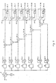
- FIG. 3 and Figure 4 illustrate embodiments of this invention, wherein the functions of n band- pass filters are provided through the use of n + 1 digital low-pass filters.
- the accumulators 28-1 to 28-6 are each provided with a co-efficient circuit 27. Thereby, the accumulators become imperfect integral circuits and provide that it is not necessary to clear previous data when accumulating new data to be input.
- a voice signal input to input terminal 1 of Figure 3 is subjected to A/D conversion at A/D converter 6.
- the output of the converter 6 is input to the digital low-pass filters 16 to 22 (n + 1 in number) and outputs Y 1 to y n+1 are obtained from the digital low-pass filters 16 to 22.
- the outputs of digital low-pass filters 16, 17, for example are respectively input to square circuits 23-1, 23-2.
- the cut-off frequencies of the digital low-pass filters 16, 17 are assumed to be f c1 , f c2 (refer to Figure 5).
- the outputs of the square circuits 23 ⁇ 1, 23 ⁇ 2 are respectively input to subtraction circuit 24-1 and outputs of subtraction circuit 24-1 are accumulated in the same way as explained with reference to Figure 2(a) at accumulator 25-1.
- low-pass filter 17 for instance, is used in common to provide the outputs from terminals 31 and 32 (i.e. outputs for two channel frequency bands).
- f c3 , f c4 , f c5 , f c6 , f C7 are cut-off frequencies of digital low-pass filters 18 to 22 respectively.
Landscapes
- Physics & Mathematics (AREA)
- Engineering & Computer Science (AREA)
- Signal Processing (AREA)
- Spectroscopy & Molecular Physics (AREA)
- General Physics & Mathematics (AREA)
- Computational Linguistics (AREA)
- Mathematical Physics (AREA)
- Health & Medical Sciences (AREA)
- Audiology, Speech & Language Pathology (AREA)
- Human Computer Interaction (AREA)
- Acoustics & Sound (AREA)
- Multimedia (AREA)
- Measurement Of Mechanical Vibrations Or Ultrasonic Waves (AREA)
- Transmission Systems Not Characterized By The Medium Used For Transmission (AREA)
Claims (5)
Applications Claiming Priority (2)
| Application Number | Priority Date | Filing Date | Title |
|---|---|---|---|
| JP136890/79 | 1979-10-23 | ||
| JP54136890A JPS584307B2 (ja) | 1979-10-23 | 1979-10-23 | スペクトル分析器 |
Publications (2)
| Publication Number | Publication Date |
|---|---|
| EP0028103A1 EP0028103A1 (fr) | 1981-05-06 |
| EP0028103B1 true EP0028103B1 (fr) | 1984-08-08 |
Family
ID=15185938
Family Applications (1)
| Application Number | Title | Priority Date | Filing Date |
|---|---|---|---|
| EP80303655A Expired EP0028103B1 (fr) | 1979-10-23 | 1980-10-16 | Analyseur de spectre |
Country Status (4)
| Country | Link |
|---|---|
| US (1) | US4358733A (fr) |
| EP (1) | EP0028103B1 (fr) |
| JP (1) | JPS584307B2 (fr) |
| DE (1) | DE3068890D1 (fr) |
Families Citing this family (14)
| Publication number | Priority date | Publication date | Assignee | Title |
|---|---|---|---|---|
| JPS57174000A (en) * | 1981-04-21 | 1982-10-26 | Tamura Kaken Co Ltd | Method of soldering printed circuit board |
| FR2509500A1 (fr) * | 1981-07-10 | 1983-01-14 | Efcis | Analyseur spectral a filtres communs a deux voies, notamment pour la reconnaissance vocale |
| JPS5884673A (ja) * | 1981-11-12 | 1983-05-20 | Tamura Kaken Kk | はんだ付け方法 |
| JPS5884672A (ja) * | 1981-11-12 | 1983-05-20 | Tamura Kaken Kk | はんだ付け方法 |
| US4556982A (en) * | 1983-06-27 | 1985-12-03 | Eaton Corporation | Energy discriminating channel select logic |
| US6811291B1 (en) * | 1984-03-28 | 2004-11-02 | Lockheed Martin Corporation | Detector for signals with harmonically related components |
| DE3505950A1 (de) * | 1985-02-21 | 1986-08-21 | Deutsche Itt Industries Gmbh, 7800 Freiburg | Integrierbare schaltungsanordnung zur identifizierung eines pilottones |
| US4847868A (en) * | 1988-02-22 | 1989-07-11 | Silicon Systems, Inc. | Non-coherent pattern detection |
| US5301123A (en) * | 1990-01-30 | 1994-04-05 | Board Of Governors For Higher Education, State Of Rhode Island And Providence Plantations | Zero crossing based spectrum analyzer and method |
| FR2685593B1 (fr) * | 1991-12-20 | 1994-02-11 | France Telecom | Dispositif de demultiplexage en frequence a filtres numeriques. |
| US20040218701A1 (en) * | 2003-04-29 | 2004-11-04 | Prashant Singh | Protocol agnostic method for adaptive equalization |
| GB2534603B (en) * | 2015-01-29 | 2019-07-31 | Michell Instruments Ltd | System for analysing the frequency of a signal, a method thereof and a system for measuring the relative phase between two input signals |
| GB201518240D0 (en) | 2015-10-15 | 2015-12-02 | Rolls Royce Plc | A method of performing real time decomposition of a signal into components |
| DE102017101653B3 (de) | 2017-01-27 | 2018-06-21 | Christian Zimmerli | System und Verfahren zur Ermittlung von zumindest einer Frequenz einer auditiven Wahrnehmung oder Schwächung der auditiven Wahrnehmung einer Person bei dieser Frequenz |
Family Cites Families (4)
| Publication number | Priority date | Publication date | Assignee | Title |
|---|---|---|---|---|
| US2851661A (en) * | 1955-12-06 | 1958-09-09 | Robert N Buland | Frequency analysis system |
| US3395345A (en) * | 1965-09-21 | 1968-07-30 | Massachusetts Inst Technology | Method and means for detecting the period of a complex electrical signal |
| US3789323A (en) * | 1972-05-19 | 1974-01-29 | Sigmatek Inc | Multiple input signal modulator and method therefor |
| JPS6016582B2 (ja) * | 1977-03-04 | 1985-04-26 | 日本電気株式会社 | デイジタル周波数分析装置 |
-
1979
- 1979-10-23 JP JP54136890A patent/JPS584307B2/ja not_active Expired
-
1980
- 1980-10-16 DE DE8080303655T patent/DE3068890D1/de not_active Expired
- 1980-10-16 EP EP80303655A patent/EP0028103B1/fr not_active Expired
- 1980-10-22 US US06/199,648 patent/US4358733A/en not_active Expired - Lifetime
Also Published As
| Publication number | Publication date |
|---|---|
| JPS584307B2 (ja) | 1983-01-25 |
| US4358733A (en) | 1982-11-09 |
| JPS5660358A (en) | 1981-05-25 |
| EP0028103A1 (fr) | 1981-05-06 |
| DE3068890D1 (en) | 1984-09-13 |
Similar Documents
| Publication | Publication Date | Title |
|---|---|---|
| EP0028103B1 (fr) | Analyseur de spectre | |
| US4737658A (en) | Centralized control receiver | |
| US4802222A (en) | Data compression system and method for audio signals | |
| EP0176596A1 (fr) | Circuit d'entree analogique | |
| EP0741472A3 (fr) | Méthode et circuit pour le traitement d'un signal à débit de symbole variable | |
| EP0420269A3 (fr) | Filtre numérique adaptatif comprenant un filtre passe-bas | |
| EP0657873A2 (fr) | Dispositif pour la compression et l'expansion de la largeur de bande d'un signal de parole, procédé de transmission d'un signal vocal à bande comprimée et procédé de reproduction | |
| DE2831059C2 (de) | Integrierender Kodeumsetzer | |
| CA1174384A (fr) | Transmultiplexeur numerique | |
| US4347408A (en) | Multi-frequency signal receiver | |
| EP0031085A3 (fr) | Appareil de traitement de signaux à transfert de charges | |
| JP3120931B2 (ja) | 同期加算装置 | |
| DE3750324T2 (de) | Vereinfachte Zurückgewinnung von Daten aus Signalen mit Quadraturträgern. | |
| CN207995070U (zh) | 一种数字信号和模拟信号转换装置 | |
| KR100687132B1 (ko) | 시간 이산 필터 및 톤 검출기 | |
| CN1191537C (zh) | 锚定物理实现滤波器冲激频率响应预定点的设备和方法 | |
| US5453741A (en) | Sampling frequency converter | |
| JPH0632023B2 (ja) | 音声分析装置 | |
| EP1453265A1 (fr) | Procedes de transmission d'informations | |
| JPS59122135A (ja) | 音声圧縮伝送方式 | |
| SU1145485A1 (ru) | Цифровое устройство преобразовани групповых сигналов систем св зи с частотным разделением каналов | |
| SU1320769A1 (ru) | Цифровой измеритель малых значений коэффициента гармоник | |
| CN100455006C (zh) | 应用于atsc高清数字电视上的变频多级滤波方法 | |
| SU805192A1 (ru) | Цифровой многоканальный спектральныйАНАлизАТОР элЕКТРичЕСКиХ СигНАлОВ | |
| SU974374A1 (ru) | Цифровой анализатор спектра |
Legal Events
| Date | Code | Title | Description |
|---|---|---|---|
| PUAI | Public reference made under article 153(3) epc to a published international application that has entered the european phase |
Free format text: ORIGINAL CODE: 0009012 |
|
| AK | Designated contracting states |
Designated state(s): DE FR GB |
|
| RBV | Designated contracting states (corrected) |
Designated state(s): DE FR GB |
|
| 17P | Request for examination filed |
Effective date: 19810730 |
|
| GRAA | (expected) grant |
Free format text: ORIGINAL CODE: 0009210 |
|
| AK | Designated contracting states |
Designated state(s): DE FR GB |
|
| REF | Corresponds to: |
Ref document number: 3068890 Country of ref document: DE Date of ref document: 19840913 |
|
| ET | Fr: translation filed | ||
| PLBE | No opposition filed within time limit |
Free format text: ORIGINAL CODE: 0009261 |
|
| STAA | Information on the status of an ep patent application or granted ep patent |
Free format text: STATUS: NO OPPOSITION FILED WITHIN TIME LIMIT |
|
| 26N | No opposition filed | ||
| PGFP | Annual fee paid to national office [announced via postgrant information from national office to epo] |
Ref country code: GB Payment date: 19890930 Year of fee payment: 10 |
|
| PGFP | Annual fee paid to national office [announced via postgrant information from national office to epo] |
Ref country code: FR Payment date: 19891030 Year of fee payment: 10 |
|
| PGFP | Annual fee paid to national office [announced via postgrant information from national office to epo] |
Ref country code: DE Payment date: 19891223 Year of fee payment: 10 |
|
| PG25 | Lapsed in a contracting state [announced via postgrant information from national office to epo] |
Ref country code: GB Effective date: 19901016 |
|
| GBPC | Gb: european patent ceased through non-payment of renewal fee | ||
| PG25 | Lapsed in a contracting state [announced via postgrant information from national office to epo] |
Ref country code: FR Effective date: 19910628 |
|
| PG25 | Lapsed in a contracting state [announced via postgrant information from national office to epo] |
Ref country code: DE Effective date: 19910702 |
|
| REG | Reference to a national code |
Ref country code: FR Ref legal event code: ST |