EP0028721B1 - Tintenstrahl-Drucker für das Drucken von rechts nach links oder von links nach rechts - Google Patents
Tintenstrahl-Drucker für das Drucken von rechts nach links oder von links nach rechts Download PDFInfo
- Publication number
- EP0028721B1 EP0028721B1 EP80106259A EP80106259A EP0028721B1 EP 0028721 B1 EP0028721 B1 EP 0028721B1 EP 80106259 A EP80106259 A EP 80106259A EP 80106259 A EP80106259 A EP 80106259A EP 0028721 B1 EP0028721 B1 EP 0028721B1
- Authority
- EP
- European Patent Office
- Prior art keywords
- signal
- printing
- characters
- supply means
- carriage
- Prior art date
- Legal status (The legal status is an assumption and is not a legal conclusion. Google has not performed a legal analysis and makes no representation as to the accuracy of the status listed.)
- Expired
Links
- 230000015654 memory Effects 0.000 claims description 35
- 230000002441 reversible effect Effects 0.000 claims description 12
- 238000001514 detection method Methods 0.000 claims description 2
- 230000004044 response Effects 0.000 claims 4
- 230000005284 excitation Effects 0.000 description 15
- 235000014676 Phragmites communis Nutrition 0.000 description 14
- 230000006870 function Effects 0.000 description 12
- 238000010586 diagram Methods 0.000 description 7
- 230000007246 mechanism Effects 0.000 description 6
- 230000007423 decrease Effects 0.000 description 4
- 230000000694 effects Effects 0.000 description 4
- 241000369389 Thereva Species 0.000 description 3
- 230000008901 benefit Effects 0.000 description 3
- 102100038576 F-box/WD repeat-containing protein 1A Human genes 0.000 description 2
- 101001030691 Homo sapiens F-box/WD repeat-containing protein 1A Proteins 0.000 description 2
- 101000709368 Mus musculus S-phase kinase-associated protein 2 Proteins 0.000 description 2
- 230000002457 bidirectional effect Effects 0.000 description 2
- 230000005540 biological transmission Effects 0.000 description 2
- 239000013078 crystal Substances 0.000 description 2
- 238000000034 method Methods 0.000 description 2
- 241001247437 Cerbera odollam Species 0.000 description 1
- 230000003321 amplification Effects 0.000 description 1
- 238000006073 displacement reaction Methods 0.000 description 1
- 230000006698 induction Effects 0.000 description 1
- 238000003199 nucleic acid amplification method Methods 0.000 description 1
- 230000008569 process Effects 0.000 description 1
- 230000000750 progressive effect Effects 0.000 description 1
- 230000009467 reduction Effects 0.000 description 1
- 230000008054 signal transmission Effects 0.000 description 1
Images


Classifications
-
- B—PERFORMING OPERATIONS; TRANSPORTING
- B41—PRINTING; LINING MACHINES; TYPEWRITERS; STAMPS
- B41J—TYPEWRITERS; SELECTIVE PRINTING MECHANISMS, i.e. MECHANISMS PRINTING OTHERWISE THAN FROM A FORME; CORRECTION OF TYPOGRAPHICAL ERRORS
- B41J2/00—Typewriters or selective printing mechanisms characterised by the printing or marking process for which they are designed
- B41J2/005—Typewriters or selective printing mechanisms characterised by the printing or marking process for which they are designed characterised by bringing liquid or particles selectively into contact with a printing material
- B41J2/01—Ink jet
- B41J2/07—Ink jet characterised by jet control
-
- B—PERFORMING OPERATIONS; TRANSPORTING
- B41—PRINTING; LINING MACHINES; TYPEWRITERS; STAMPS
- B41J—TYPEWRITERS; SELECTIVE PRINTING MECHANISMS, i.e. MECHANISMS PRINTING OTHERWISE THAN FROM A FORME; CORRECTION OF TYPOGRAPHICAL ERRORS
- B41J19/00—Character- or line-spacing mechanisms
- B41J19/14—Character- or line-spacing mechanisms with means for effecting line or character spacing in either direction
- B41J19/142—Character- or line-spacing mechanisms with means for effecting line or character spacing in either direction with a reciprocating print head printing in both directions across the paper width
Definitions
- the present invention relates to an inkjet printer capable of printing from left to right or from right to left.
- the print head print is mounted on a carriage in order to move from left to right to print characters in the French or English language, for example, these two languages normally written in this direction.
- the print head mounted on the carriage moves relative to the print medium, which generally consists of paper, a character then being printed on the latter by droplets selected ink from the print head.
- the ink jet printer of the present invention makes it possible to print characters from left to right or from right to left depending on the language in question.
- a single printer can therefore be used to print various languages, whether these are written from left to right or from right to left.
- Each of the languages that this printer can print can be stored as an assortment of separate characters as described in US-A-3,964,591. Although said patent does not include any description of a assortment of characters relating to a language printed only from right to left, such characters could be stored in an appropriate memory.
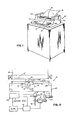
- an inkjet printer 10 comprising a keyboard 11 which allows it to operate in conversational mode.
- the keyboard 11 includes keys 12 which allow the operator to select characters which will be printed on a printing medium 14 consisting, for example, of paper, by means of ink droplets from an ink jet pressure 15 (see Figure 2) emanating from a nozzle 16, the droplets striking the printing medium 14 as indicated at 16 '.
- the nozzle 16 which can optionally be replaced by several nozzles, is mounted on a carriage 17 which moves along a first axis. This is practically horizontal and practically perpendicular to a second axis along which the printing medium 14 moves relative to the carriage 17.
- the pressurized ink jet 15 which leaves the nozzle 16 emanates from a droplet generator 18.
- the latter contains a piezoelectric crystal which is excited by an excitation circuit 19 (see FIG. 3) at a frequency chosen so causing the jet 15 to be divided into droplets having practically uniform dimensions and spacing as described in European patent application No. 0791039266 filed by the applicant on October 12, 1979 (Publication No. 0013296).
- the ink droplets thus formed pass through a charging electrode 20, then through deflection electrodes 21 so as to strike the printing medium 14 at desired locations and thus form the characters chosen.
- the carriage 17 is driven along the first axis in one direction or the other, as indicated by the arrow 22 in FIG. 2, by reversible drive means 23.
- the latter comprise, as described in the European patent application No. 791036171 filed by the applicant on September 24, 1979 (Publication No. 0010199), a direct current motor 24 which is connected by suitable means, such as a toothed belt 25, to a drum 26 on which a cable 27 is wound several times.
- the opposite ends of the cable 27 are connected to the opposite ends of the carriage 17 by means of several pulleys 28.
- the direction in which the motor 24 turns therefore makes it possible to determine the direction in which the carriage 17 moves along the first axis by report to print media 14.
- the printer 10 therefore comprises a locating device position, network which is of the type described in detail in European patent application No. 791015613 filed by the applicant on May 22, 1979. (Publication No. 0006441).
- This tracking device comprises a detector 30 (see Figure 3), which comprises a network 31 (see Figure 2), used in conjunction with a light emission and detection module 32 and a mirror 33, to supply electrical signals designated GRAA and GRBB (see Figures 9 to 12) which are 90 ° out of phase with each other, so as to indicate both the position of the carriage 17 with respect to a left reed switch 34 (see Figure 1) and to a straight reed switch 35, and in the direction of movement of the carriage 17 relative to one of the switches 34 and 35.
- a detector 30 see Figure 3
- a network 31 see Figure 2
- GRBB see Figures 9 to 12
- the switches 34 and 35 occupy fixed positions respectively located beyond the extreme left and right limits of the text printed on the support 14. Each of the switches 34 and 35 makes it possible to indicate a specific position of the carriage 17 when the latter is in position of one of these switches.
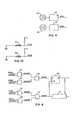
- the module 32 comprises a pair of detectors 36 and 37 (see Figure 4).
- the detector 36 transmits its output signal to a circuit 38 called channel A
- the detector 37 transmits its output signal to a circuit 39 called channel B.
- the circuits 38 and 39 are described in detail in said patent application European No. 0791015613.
- the output signals of circuits 38 and 39 are respectively the signals GRAA and GRBB already mentioned. As shown in Figures 9 to 12, the GRAA and GRBB signals are mutually 90 ° out of phase, and are square signals. The signals GRAA and GRBB are used to indicate both the position occupied by the carriage 17 (see Figure 1) relative to one of the switches 34 and 35 as well as the direction in which the carriage 17 moves relative to one of these switches.
- the carriage 17 is driven by the motor 24 ( Figure 2) so that this carriage moves along the first axis in one direction or the other relative to the scale 31.
- the speed and the direction of rotation of the motor 24 are controlled by a control circuit 40, which is described in more detail in the aforementioned European patent application No. 0791036171 and which. supplies signals to a drive circuit 41, described in more detail in this latter patent application.
- the control circuit 40 is informed of the speed and direction of rotation of the motuer 24 by means of a coding signal.
- the motor 24 has a shaft on which is mounted a coding wheel 42 which rotates at the same time as the motor.
- the coding wheel 42 has at its periphery a number of slots having the same angular spacing which pass between a diode or a photoluminescent transistor 43, on the one hand, and, on the other hand, a phototransistor and amplifier 44 forming part of 'an encoder 44'. In this way, a pulse is generated by the phototransistor 44 when the light emitted by the diode or by the transistor 43 passes through one of the slots of the wheel 42 and strikes this phototransistor.
- the control circuit 40 is part of a mechanism control circuit 45 (see Figure 3) incorporated into the electronic circuits 46 of the system, which are practically the same as those used in the IBM 6640 printer, model 1, which are described. in the aforementioned European patent application No. 0791039266, with the exception of circuit 45.
- the latter is connected via a bidirectional data bus 47 to an interface 49 of inkjet printer as described in said European patent application No. 0791039266.
- Each of the character selection keys 12 (see FIG. 1) and of the function keys 49 of the keyboard 11 makes it possible to transmit different signals to a microprocessor 50 (see FIG. 3).
- the latter, as well as keys 12 and 49 of the keyboard 11 or any other input device, function as the main system relative to the electronic circuits 46 shown diagrammatically in FIG. 3.
- the microprocessor 50 provides input to the interface 48 via an input / output channel 51 as a function of the signal received from the keyboard 11 (FIG. 1).
- channel 51 As specified in the aforementioned European patent application No. 0791039266, channel 51 (see Figure 3) comprises eight data lines, four control lines, an interrupt line and a line used for signal transmission provided by the main clock, a total of fourteen lines.
- the interface 48 conventionally provides gate signals, logic signals, synchronization signals, appropriate amplification and signals emanating from a main clock to a system clock 52 in which voltage dividing circuits divide the frequency of the signals received from the main clock into a number of frequencies, as described in detail in said European patent application No. 0791039266.
- the system clock 52 also makes it possible to excite the circuit 19, which acts on the piezoelectric crystal of the droplet generator 18, at the required frequency.
- the signals from the input / output channel 51 can be appropriately amplified and buffered so that instructions can be received in series from the microprocessor 50.
- the inkjet printer 10 of FIG. 1 has a memory 53 (FIG. 3) comprising several zones in each of which are stored information relating to the printing of characters forming part of an assortment relating to a specific language such as than French, English, Hebrew or Arabic.
- the storage of information in this different areas of the memory 53 is described in detail in the aforementioned patent US-A-3964591.
- the memory 53 has at least two of said zones respectively containing information relating to the printing of characters from left to right, as in the case of the French or English language, and from right to left, as in the case of Hebrew or Arabic.
- the memory 53 can include any number of said zones and is an unalterable memory.
- Each of the languages to which the information stored in the different areas of the memory 53 relates is selected by the operator by pressing at least one of the function keys 49 (see FIG. 1) of the keyboard 11. It may be necessary to press two of the keys 49 depending on whether the memory area 53 selected by the operator contains information relating to a language which is written from right to left or from left to right.
- Pressing one of the keys 49 has the effect of transmitting a signal to the microprocessor 50 of FIG. 3. The latter then transmits three bytes, via the eight data lines of the input / output channel 51 , at interface 48.
- the interface 48 then transmits an eight-bit signal via the bidirectional data bus 47 to a character generator 55.
- This signal makes it possible to select one of the zones of the memory 53 in the manner described in more detail. in the aforementioned patent US-A-3,964,591.
- the character generator 55 transmits an address via a bus 56 to the memory 53 in order to select the zone of the latter defined by the key 49 pressed by the operator.
- the subsequent pressing by the operator of various character selection keys 12 of the keyboard 11 results in the transmission of print commands to the mechanism control circuit 45 (FIG. 3) and to the character generator 55, by the same so that in the case of the IBM 6640 model 1 printer, (cf. the aforementioned European patent application No. 0791039266).
- This process includes the transmission of an address, from the character generator 55, to the memory 53 via the bus 56 to allow the selection of the character to be printed.
- the data extracted from the memory 53 are transmitted via a data bus 58 to the generator 55 and relate to a single vertical scan carried out by the print head of the printer 10 to form part of the particular character that the 'We wish to print, as described in more detail in said European patent application No. 0791039266.
- the generator 55 transmits a signal to the mechanism control circuit 45 via a control bus 59.
- the circuit 45 is put in a state in which it is ready to print.
- the generator 55 transmits a signal "ready for sweep ", via a bus 60, which is a 40-bit line, to a logic circuit for positioning the droplets 61, as described in more detail in the aforementioned European patent application No. 0791039266.
- Logic circuit 61 receives a second signal from circuit 45 via a bus 62. This last signal is said to be "start of scanning” and indicates that the carriage 17 occupies a predetermined position along the first axis, this position being given by the detector 30 of FIG. 3.
- the IBM 6640 printer model 1
- the IBM 6640 printer allows to compensate for the aerodynamic phenomena to which the ink droplets are subject and to correct the induction resulting from the presence of charged droplets which precedes a given droplet, so that the droplets used for printing can strike the printing medium 14 in FIG. 3 at the required locations.
- the compensation technique used in the IBM 6640 model 1 printer is described in US-A-4,086,601.
- a shift register that includes the logic circuit 61 of Figure 3 transmits an address, via a bus 63, to a correction data memory 64, which is a searchable table.
- the memory 64 transmits a signal representing the correct data, via a data bus 65, to the logic circuit 61.
- This latter signal is itself transmitted by the logic circuit 61 to a digital-analog converter (DAC) 67 via a bus 66.
- the converter 67 applies a voltage to the charge electrode 20 of FIG. 2.
- DAC digital-analog converter
- a charge of a selected magnitude is selectively applied to the ink droplets from the jet 15 such that each of the droplets used for printing strikes the support 14 at a desired location so as to form the character chosen as a function of the scanning information supplied to the character generator 55 by the memory 53.
- the mechanism control circuit 45 performs a large number of distinct functions.
- One of these consists in controlling and ensuring the chronology of a circuit 70, which monitors the ink jet 15 of FIG. 2 and determines at predetermined intervals if the height reached by a droplet which made the The object of a deviation is within the limits of certain tolerances.
- the circuit 70 of Figure 3 is described and shown in more detail in US-A-4,136,435.
- the control circuit 45 also includes a common decoder used for the purpose of synchronization operations and control of the ink pump.
- a common decoder used for the purpose of synchronization operations and control of the ink pump.
- An example of servo-control of this pump is cited in patent US-A-3,787,882.
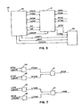
- the control circuit 45 further comprises a logic circuit 71 (see FIG. 5) to which the signals GRAA and GRBB from the position detector 30 of FIG. 3 are applied.
- the signal GRAA is applied, from the circuit 38 of FIG. 4 , to one of the inputs of each of two AND gates 72 and 73 (see Figure 6), while the GRBB signal is applied, from circuit 39 of Figure 4, to one of the inputs of each of two gates AND 74 and 75 (see Figure 6).
- the second input of each of the AND gates 72 and 75 receives a LGMODE signal, and the other input of each of the AND gates 73 and 74 receives a LGMODE * signal .
- the LGMODE signal is at the high level
- the LGMODE * signal is at the low level, and vice versa.
- the LGMODE signal is applied from a mechanical control logic circuit 76 ( Figure 5) that includes the control circuit 45.
- This signal is high when one of the function keys 49 ( Figure 1) of the keyboard 11 is pressed by the operator to select one of the areas of memory 53 ( Figure 3) in which are stored information relating to the printing of characters from left to right, as in the case of the French language, on the medium of printing 14.
- This same signal is at a low level when one of the function keys 49 is pressed by the operator to select one of the areas of the memory 53 containing information relating to the printing of characters from right to left , as in the case of Hebrew or Arabic.
- the high or low level of the LGMODE signal indicates the direction in which the carriage 17 moves to print characters.
- the logic circuit 71 includes an inverter so that the state of the LGMODE * signal is the inverse of that of the LGMODE signal. Consequently, when the LGMODE signal is at the high level and the LGMODE * signal is at the low level, the output of the AND gate 72 of FIG. 6 is a GRAA1A signal of high level when the GRAA signal is at the high level, and a low GRAA1A signal when the GRAA signal is low.
- the output of the AND gate 74 is a GRAA1B low level signal as long as the LGMODE sign is high because the LGMODE * signal is low.
- the outputs of AND gates 72 and 74 are applied to the inputs of an EXCLUSIVE OR gate 78.
- the output of the latter is therefore a GRAA1 signal of high level each time its inputs are opposite. Consequently, when the LGMODE signal is at the high level, the GRAA1 signal obtained at the output of the EXCLUSIVE OR gate 78 is the same as the GRAA signal, so that the GRAA1 signal goes to the high level and to the low level so as to constitute a square signal similar to the GRAA signal shown in Figure 9.
- the output of the AND gate 73 is a signal GRBB1B of low level each time that the signal LGMODE is on the high level.
- the outputs of AND gates 73 and 75 are applied to the inputs of an EXCLUSIVE OR gate 79.
- the output of the latter is therefore a signal GRBB1, which is the same as the GRBB signal when the LGMODE signal is high.
- the GRBB1 signal is therefore a square signal in phase with the GRBB signal, as shown in Figure 9.
- the signal GRAA1 obtained at the output of the AND gate 74 of Figure 6 is the same as the signal GRBB obtained at the output of circuit 39 of Figure 4.
- the signal GRAA1 obtained at the output of the OR gate 78 of Figure 6 is then in phase with the GRBB signal and not with the GRAA signal, as can be seen in Figure 10.
- the signal GRBB1 B obtained at the output of the AND gate 73 of FIG. 6 follows the signal GRAA when the signal LGMODE * is at the high level.
- the GRBB1 signal obtained at the output of the EXCLUSIVE OR gate 79 is therefore in phase with the GRAA signal, as shown in Figure 10 when no character is printed from right to left.
- the signal GRAA1 supplied by the gate OR EXCLUSIVE 78 of Figure 6 therefore always indicates the direction in which the carriage 17 moves to print characters on the print medium 14, while the signal GRBB1 obtained at the exit of the door OR EXCLUSIVE 79 of Figure 6 always indicates the direction in which the carriage 17 moves to return to its starting point and start printing a new line of characters.
- the signal GRAA1 supplied by gate 78 is applied to the input D of a D-type flip-flop 80.
- the signal GRBB1 supplied by gate 79 is applied to the clock input (CK) of the flip-flop 80 as well as a counter 81, which also receives the signal obtained at the output Q of this flip-flop. This arrangement of the flip-flop 80 and the counter 81 is described in the aforementioned patent application No. 791015613.
- the state of the signal obtained at the output Q of the flip-flop 80 determines whether the counter 81 performs progressive or declining counting each time the signal GRBB1 which it receives from the EXCLUSIVE OR gate 79 goes high.
- the digital output of the counter 81 makes it possible to indicate the position occupied by the carriage 17 relative to the left reed switch 34 or to the right reed switch 35, depending on the direction in which the printing of the characters must have location.
- the carriage 17 is successively moved until it is in the excitation position of the left switch 34, then of the right switch 35, before removing it. put in a determined print start position. If printing is to take place from right to left, the carriage 17 is successively moved until it is in the excitation position of the right switch 35, then of the left switch 35, before starting the impression.
- a high level LFSW signal (see FIG. 13) is generated and transmitted to the logic circuit 71 of FIG. 5.
- a high level RFSW signal (FIG. 13) is generated and transmitted to the logic circuit 71 of the control circuit 45.
- the LFSW signal ( Figure 13) is applied to one of the inputs of an ET 85 gate (see Figure 7), the other input of which receives the LGMODE signal.
- the RFSW signal is applied to one of the inputs of an AND gate 86, the other input of which receives the LGMODE * signal .
- the output of the gate ET 85 goes to the high level when the LFSW signal is at the high level, because the carriage 17 is in the excitation position of the left reed switch 34.
- a high level LFSWA signal is then obtained at the output of the AND gate 85 and applied to one of the inputs of an EXCLUSIVE OR gate 87.
- the output of the AND gate 86 is then always a low level LFSW signal due to the fact that the LGMODE * signal is always low. Consequently, a high level LHSW signal is obtained at the output of the EXCLUSIVE OR gate 87 each time the LFSW signal goes high, the LGMODE signal being high.
- the LHSW signal supplied by the EXCLUSIVE OR gate 87 is used to set the counter 81 of FIG. 6 to a determined value. The latter makes it possible to know at any time the position occupied by the carriage 17 relative to the left switch 34 in the case of printing carried out from left to right.
- the LGMODE signal When the characters have to be printed from right to left, the LGMODE signal is always at the low level so that the LFSWA signal obtained at the output of the ET 85 gate (see Figure 7) is always at the low level.
- the LGMODE * signal is always high while printing characters from right to left. Consequently, when the carriage 17 is put in the excitation position of the right reed switch 35, the signal RFSW goes high, so that the signal RFSWB obtained at the output of the AND gate 86 of FIG. 7 is at the high level. As a result, the LHSW signal obtained at the output of the EXCLUSIVE OR gate 87 is again at the high level. Since the high level LHSW signal is used to set the counter 81 of FIG.
- the value of the counter 81 always indicates the position occupied by the carriage 17 relative to the switch 35 in the case of a printing carried out from right to left.
- the counter value 81 therefore always indicates the position occupied by the carriage 17 with respect to a fixed reference position, which is either the left switch 34, or the right switch 35 depending on the direction in which the carriage 17 must move to print characters.
- the position of the carriage 17 is therefore always known with respect to this fixed reference position.
- One of the states of the signal obtained at the output Q of the flip-flop 80 of FIG. 6 indicates the direction in which the carriage 17 moves and in which the printing of the characters takes place, whether this printing takes place from right to left or left to right.
- the signal obtained at the output Q of the flip-flop 80 is at the high level, this indicates, for example, that the carriage 17 is moving in the direction in which the printing actually takes place, whether it is printing from right to left or from left to right.
- this signal is at a low level when the carriage 17 moves in the direction in which no printing takes place, whether the printing is carried out from left to right or from right to left.
- the signal GRAA1 is applied to the input D of the flip-flop 80 and the signal GRBB1 is applied to the input CK of this flip-flop, and this permanently.
- the signal GRAA1 is the signal GRAA when the carriage 17 moves from left to right to print characters and is the signal GRBB when the carriage 17 moves in the opposite direction.
- the signal GRAA1 is at the low level when the signal GRBB1 goes to the high level when the carriage 17 moves from right to left in the case where the printing of the characters takes place from left to right. This therefore lowers the signal obtained at the output Q of the flip-flip 80.
- the value of the counter 81 decreases by one.
- the value of the counter 81 therefore decreases when the carriage 17 moves from right to left, that is to say the direction in which no printing takes place, when the printing of the characters is carried out from left to right.
- the signal GRAA1 is at the low level when the signal GRBB1 goes to the high level, as indicated in FIG. 12, during the movement of the carriage 17 from left to right. This therefore causes the signal obtained at the output Q of the flip-flop 80 to go low to indicate that the carriage 17 is moving in the direction in which no printing takes place.
- the carriage 17 is also placed in the excitation position of that of the reed switches 34 and 35 which has not been used to define the value of the counter 81.
- the signal thus generated by the second switch, 34 or 35 is used for other purposes, for example to indicate the appearance of an error or the presence of a control cycle.
- the signal LFSW which goes high when the carriage 17 is put in the excitation position of the left reed switch 34, is also applied to one of the inputs of an AND gate 89 (see Figure 7).
- the other input of the latter receives the LGMODE * signal.
- the RFSW signal which goes high when the right reed switch 35 is excited by the carriage 17, is applied to one of the inputs of an AND gate 90 ( Figure 7), the other input of which receives the signal LGMODE.
- the AND gate 90 of FIG. 7 provides at its output a RFSWA signal of high level when the signal RFSW is at the high level.
- the AND gate 89 provides at its output a RFSWB signal of high level when the LFSW signal goes to high level due to the fact that the carriage 17 is in the excitation position of the left switch 34.
- the outputs of AND gates 89 and 90 are applied to the inputs of an EXCLUSIVE OR gate 91.
- the EXCLUSIVE OR gate 91 provides a signal at its output.
- RHSW high level to indicate that the carriage 17 is in the excitation position of the right switch 35. This RHSW high level signal is used for the needs of other functions, for example for the purposes of a cycle of enslavement.
- the LGMODE * signal is at the high level.
- Gate ET 90 will therefore not present a high RFSWA signal at its output, the LGMODE signal being at low level.
- AND gate 89 provides a high level RFSWB signal when the LFSW signal goes high due to the fact that the carriage 17 is in the energized position of the left reed switch 34. Consequently, the signal RHSW obtained at the exit of the EXCLUSIVE OR gate 91 of Figure 7 goes high when the left switch 34 is activated by the carriage 17 when the memory area 53 which has been selected requires the printing of characters from right to left.
- the high level RHSW signal is used for the needs of other functions, for example, for the purposes of a servo cycle.
- the speed and direction of rotation of the motor 24 in Figure 2 are controlled by a circuit 40, which is part of the mechanism control circuit 45 in Figure 3.
- the logic circuit 76 (see Figure 5) of the control circuit 45 supplies CARRTI and HIGHI signals to the circuit 40 as described in the aforementioned European patent application No. 0791036171. These signals determine the speed of rotation of the motor 24.
- the logic circuit 76 also provides a DIR signal as a function of an input signal received by the interface 48 (FIG. 3) of the microprocessor 50.
- this DIR signal is at the high level, the carriage 17 must move in the direction in which the printing of the characters must take place, that is to say from left to right when the characters are to be printed from left to right and from right to left when the characters are to be printed from right to left.
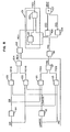
- the DIR signal generated by circuit 76 is applied to logic circuit 71 ( Figure 5). As shown in Figure 8, the DIR signal is applied to one of the two inputs of an AND gate 93, the other input of which receives the LGMODE signal. The DIR signal is inverted by the inverter 94, so that the output of the latter is a DIR signal, which is applied to one of the inputs of an AND gate 95, the other input of which receives the LGMODE * signal . , which is the signal obtained at the output of an inverter 95 which receives the LGMODE signal.
- the signal FRD obtained at the output of the OR gate 97 is applied to one of the inputs of an AND gate 98, the other input of which receives a signal RN.
- the latter is supplied by the logic circuit 76 of FIG. 5 which is part of the control circuit 45 and is at the high level each time that the motor 24 has to rotate, whatever the direction of its rotation.
- the signal RN is at the high level. If the signal DIR is at the high level to indicate that the carriage 17 must move in the direction in which the printing of the characters must take place, the signal LGMODE ets at the high level to indicate that the characters must be printed by the carriage 17 from left to right, and the signal RN is at the high level to indicate that the motor 24 must turn, and under these conditions a signal FRD of high level is obtained at the output of the gate AND 98.
- the signal FRD is applied to one of the inputs of an NI 99 gate which, with an NI 100 gate, constitutes a flip-flop 101.
- the output of the NI 99 gate is applied to one of the inputs of the NI 100 gate the other input of which receives a REV signal from an AND gate 102.
- the output of the NI 100 gate constitutes the other input of the NI 99 gate.
- the output of the NI 100 gate makes it possible to obtain a FWDI signal at the , exit from rocker 101.
- the signal FRD supplied by the AND gate 98 is at the high level due to the fact that the carriage 17 must move from left to right, the signal FWDI supplied by the flip-flop 101 is at the high level.
- the signal FWD1 is applied to the control circuit 40 to determine the direction in which the motor 24 rotates. If this signal is high, the motor 24 rotates so that the carriage 17 moves from left to right, and s' it is at the low level, the carriage moves from right to left.
- the LGMODE * signal is at the high level, as previously mentioned. If the DIR signal is at the low level, so that the DIR signal is at the high level, no character should be printed during the movement of the carriage 17, the two inputs of the AND gate 95 are at the high level, and this door provides a high level FRDA signal. As a result, the signal FRD supplied by the OR gate 97 goes high.
- the AND gate 98 supplies a signal FRD of high level. This again has the effect of making the signal FWDI supplied by the flip-flop 101 go high, so that the carriage 17 moves from left to right, which is the direction in which no impression occurs when the language whose it is written from right to left.
- the high level FWDI signal always has the effect of causing the carriage 17 to move from left to right. This happens when printing has to take place from left to right and that the carriage 17 must return to its starting point to start printing another line of characters when the latter are written from right to left.
- the DIR signal is also applied to one of the inputs of an ET 103 gate ( Figure 8), the other input of which receives the LGMODE * signal. Consequently, these latter signals are high when the carriage 17 has to move from right to left for the purpose of printing.
- the output of the AND gate 103 is constituted by a signal REVB, which is applied to one of the inputs of an OR gate 104.
- the output of the latter is constituted by a REV signal, which is applied to one of the inputs of the AND gate 102, the other input of which receives the signal RN.
- the signal REV is at the high level since the signal REVB coming from the AND gate 103 is also at the high level.
- the AND gate 102 provides a high level REV signal.
- the signal FRD supplied by the AND gate 98 is at the low level.
- the high level REV signal supplied by the ET gate 102 results in obtaining a low level FWDI signal at the output of the flip-flop 101. Therefore, the carriage 17 must move from right to left. This happens when you want to print characters from right to left, which is indicated by the fact that the DIR and LGMODE * signals are both high.
- An AND gate 105 receives on its two inputs the signal LMf and the signal LGMODE. When these two signals are at high level, the AND gate 105 provides a REVA signal at high level. This occurs when the carriage 17 has to move from right to left without printing characters, the latter having to be printed from left to right as indicated by the fact that the signals DIR and LGMODE are at the high level.
- the REVA signal obtained at the output of AND gate 105 is applied to one of the inputs of OR gate 104. Therefore, when the REVA signal is at high level, a high signal REV signal is obtained at the output from door 104.
- the FWDI signal provided by the flip-flop 101 is used in the control circuit 40 ( Figure 2) as described in detail in the aforementioned patent application No. 954374.
- the state of this signal has the effect of rotating the motor 24 in the correct direction.
- the signal FRD obtained at the output of the AND gate 98 is also applied to one of the inputs of an AND gate 107 via an inverter 106.
- the signal applied to this input is therefore an FRD signal, which is the inverse of the FRD signal.
- the REV signal obtained at the output of the AND gate 102 is applied via an inverter 108 to the other input of the AND gate 107. This latter input therefore receives a REV signal, which is the inverse of the signal REV.
- the operation of the ink jet printer 10 (see Figure 1) of the present invention is described below.
- the operator presses at least one of the function keys 49 of the keyboard 11 to select one of the zones of the memory 53 (FIG. 3). If the zone thus selected contains information relating to characters whose printing requires a displacement of the carriage 17 from left to right, the signal LGMODE supplied by the logic circuit 76 (FIG. 5) of the control circuit 45 is at the high level; in the case of printing from right to left, this signal is low.
- the GRAA1 signal supplied by the gate OR EXCLUSIVE 78 of Figure 6 is the same as the GRAA signal supplied by the circuit 38 of Figure 4, as can be seen in Figures 9 and 11, and the signal GRBB1 supplied by the EXCLUSIVE OR gate 79 in Figure 6 is the same as the signal GRBB supplied by the circuit 39 in Figure 4, as shown in Figures 9 and 11.
- the counter 81 in Figure 6 is initialized when switching to the high level of the LHSW signal obtained at the exit of the gate OR EXCLUSIVE 87 of FIG. 7 due to the fact that the carriage 17 is in the excitation position of the left reed switch 34 of the Figure 1, and the position of the carriage 17, in accordance with the value of the counter 81, is determined relative to the switch 34.
- the signal LGMODE being at the high level
- the signal FWDI obtained at the output of the logic circuit 71 of FIG. 5 is at the high level when the signal DIR is at the high level at the low level when the signal DIR is at the high level.
- the carriage 17 therefore moves from left to right when the DIR signal is at the high level, printing of characters from left to right.
- the GRAA1 signal supplied by the gate OR EXCLUSIVE 78 is the GRBB signal supplied by the circuit 39, as shown in Figures 10 and 12 and the signal GRBB1 supplied by the gate OR EXCLUSIVE 79 of FIG. 6 is the signal GRAA supplied by the circuit 38 of FIG. 4, as shown in FIGS. 10 and 12. Thanks to this arrangement, the signal LHSW supplied by the door OR EXCLUSIVE 87 to initialize the counter 81 is obtained due to the passage of the RFSW signal at the high level when the carriage 17 is in the excitation position of the right reed switch 35 before the start of printing. The position of the carriage 17, in accordance with the value of the counter 81, is determined relative to the switch 34.
- the signal LGMODE being at the low level and the signal LGMODE * at the high level
- the signal FWD1 supplied by the flip-flop 101 of FIG. 8 is at the low level when the signal DIR is at the high level.
- the carriage 17 moves including from right to left, which is the direction in which the printing of the characters must take place when the signal LGMODE * is at the high level.
- the FWDI signal obtained at the output of flip-flop 101 goes to level high to cause the carriage 17 to move from left to right. This is the direction of the return of the carriage 17 when the printing of the characters takes place from right to left.
- the motor 24 is controlled via the control circuit 40, the same result could be obtained by other means.
- the outputs of ET gate 98 and 102 could be used with a different circuit to cause the motor 24 to rotate in the desired direction.
- the circuit 40 nevertheless constitutes the preferred solution for controlling the rotation of the motor 24.
- the print medium 14 moves relative to the carriage 17 along the second axis, which is substantially perpendicular to the first axis
- the print medium 14 could be placed on a flat surface , for example, and the carriage 17 could move relatively to said support along the second axis. It therefore suffices that there is a relative movement between the printing medium 14 and the carriage 17 or between the latter and the support 14.
- One of the advantages of the present invention lies in the fact that it allows the operator to see the characters forming in the direction in which the language to which they belong is written normally. Another advantage of the invention results from the fact that a single inkjet printer can be used to print characters forming part of languages which are normally written from right to left or from left to right, which means by a reduction in cost.
Landscapes
- Character Spaces And Line Spaces In Printers (AREA)
- Record Information Processing For Printing (AREA)
- Particle Formation And Scattering Control In Inkjet Printers (AREA)
- Dot-Matrix Printers And Others (AREA)
Claims (9)
Applications Claiming Priority (2)
| Application Number | Priority Date | Filing Date | Title |
|---|---|---|---|
| US92601 | 1979-11-08 | ||
| US06/092,601 US4289411A (en) | 1979-11-08 | 1979-11-08 | Multilingual ink jet printer |
Publications (3)
| Publication Number | Publication Date |
|---|---|
| EP0028721A2 EP0028721A2 (de) | 1981-05-20 |
| EP0028721A3 EP0028721A3 (en) | 1982-09-22 |
| EP0028721B1 true EP0028721B1 (de) | 1985-06-12 |
Family
ID=22234057
Family Applications (1)
| Application Number | Title | Priority Date | Filing Date |
|---|---|---|---|
| EP80106259A Expired EP0028721B1 (de) | 1979-11-08 | 1980-10-15 | Tintenstrahl-Drucker für das Drucken von rechts nach links oder von links nach rechts |
Country Status (5)
| Country | Link |
|---|---|
| US (1) | US4289411A (de) |
| EP (1) | EP0028721B1 (de) |
| JP (1) | JPS5682288A (de) |
| CA (1) | CA1130642A (de) |
| DE (1) | DE3070757D1 (de) |
Families Citing this family (17)
| Publication number | Priority date | Publication date | Assignee | Title |
|---|---|---|---|---|
| BE891911A (fr) * | 1982-01-27 | 1982-05-17 | Europ Agence Spatiale | Dispositif numerique pour commander la representation graphique de caracteres |
| JPS59154527A (ja) * | 1983-02-22 | 1984-09-03 | Tokyo Electric Co Ltd | 電子タイプライタ− |
| IT1163792B (it) * | 1983-07-15 | 1987-04-08 | Honeywell Inf Systems Italia | Apparato di controllo mircoprogrammato per stampante seriale |
| JPH0738704B2 (ja) * | 1983-08-12 | 1995-04-26 | ソニー株式会社 | テレビジヨン受像機 |
| FR2573011B1 (fr) * | 1984-11-15 | 1988-03-11 | Imaje Sa | Procede de commande de tete d'impression a jet d'encre et atelier flexible ainsi equipe |
| JPH0246490A (ja) * | 1988-08-06 | 1990-02-15 | Mitsubishi Electric Corp | メモリ回路 |
| EP0435694B1 (de) * | 1989-12-29 | 1995-08-09 | Canon Kabushiki Kaisha | Drucker und elektronische Schreibmaschine |
| JP2666202B2 (ja) * | 1991-09-11 | 1997-10-22 | キヤノン株式会社 | 障害者用意志伝達装置 |
| US7039637B2 (en) | 1998-12-31 | 2006-05-02 | International Business Machines Corporation | System and method for evaluating characters in an inputted search string against a character table bank comprising a predetermined number of columns that correspond to a plurality of pre-determined candidate character sets in order to provide enhanced full text search |
| US6813747B1 (en) | 1998-12-31 | 2004-11-02 | International Business Machines Corporation | System and method for output of multipart documents |
| US6760887B1 (en) | 1998-12-31 | 2004-07-06 | International Business Machines Corporation | System and method for highlighting of multifont documents |
| US7031002B1 (en) | 1998-12-31 | 2006-04-18 | International Business Machines Corporation | System and method for using character set matching to enhance print quality |
| US6718519B1 (en) | 1998-12-31 | 2004-04-06 | International Business Machines Corporation | System and method for outputting character sets in best available fonts |
| US7103532B1 (en) | 1998-12-31 | 2006-09-05 | International Business Machines Corp. | System and method for evaluating character in a message |
| US6539118B1 (en) | 1998-12-31 | 2003-03-25 | International Business Machines Corporation | System and method for evaluating character sets of a message containing a plurality of character sets |
| US7191114B1 (en) | 1999-08-27 | 2007-03-13 | International Business Machines Corporation | System and method for evaluating character sets to determine a best match encoding a message |
| US20040205675A1 (en) * | 2002-01-11 | 2004-10-14 | Thangaraj Veerappan | System and method for determining a document language and refining the character set encoding based on the document language |
Family Cites Families (10)
| Publication number | Priority date | Publication date | Assignee | Title |
|---|---|---|---|---|
| DE2143571A1 (de) * | 1971-08-31 | 1973-03-15 | Siemens Ag | Tintenstrahlschreibeinrichtung, mit einem in zeilenrichtung beweglichen schreibkopf |
| US3970183A (en) * | 1974-06-05 | 1976-07-20 | Centronics Data Computer Corporation | Random access line printer |
| US3964591A (en) * | 1975-06-10 | 1976-06-22 | International Business Machines Corporation | Font selection system |
| US4150902A (en) * | 1976-07-19 | 1979-04-24 | Ing. C. Olivetti & C. | Electronic printer having a single tracing element for tracing out alphanumeric characters |
| JPS5353926A (en) * | 1976-10-26 | 1978-05-16 | Tokyo Electric Co Ltd | Reciprocating print unit for dot printer |
| DE2721654C3 (de) * | 1977-05-13 | 1980-01-10 | Triumph-Werke Nuernberg Ag, 8500 Nuernberg | Schreibmaschine mit einem auswechselbaren Typenkörper |
| US4152083A (en) * | 1977-08-10 | 1979-05-01 | Teletype Corporation | Margin control for printing apparatus |
| JPS5341491A (en) * | 1977-09-14 | 1978-04-14 | Terukatsu Miyauchi | Enzymatic reaction method |
| US4204777A (en) * | 1978-01-16 | 1980-05-27 | Ncr Corporation | Matrix printer control system |
| US4180703A (en) * | 1978-06-28 | 1979-12-25 | International Business Machines Corporation | Bi-directional, self imaging grating detection apparatus |
-
1979
- 1979-11-08 US US06/092,601 patent/US4289411A/en not_active Expired - Lifetime
-
1980
- 1980-09-18 CA CA360,476A patent/CA1130642A/en not_active Expired
- 1980-10-15 DE DE8080106259T patent/DE3070757D1/de not_active Expired
- 1980-10-15 EP EP80106259A patent/EP0028721B1/de not_active Expired
- 1980-11-07 JP JP15602080A patent/JPS5682288A/ja active Pending
Also Published As
| Publication number | Publication date |
|---|---|
| JPS5682288A (en) | 1981-07-04 |
| CA1130642A (en) | 1982-08-31 |
| DE3070757D1 (en) | 1985-07-18 |
| EP0028721A3 (en) | 1982-09-22 |
| US4289411A (en) | 1981-09-15 |
| EP0028721A2 (de) | 1981-05-20 |
Similar Documents
| Publication | Publication Date | Title |
|---|---|---|
| EP0028721B1 (de) | Tintenstrahl-Drucker für das Drucken von rechts nach links oder von links nach rechts | |
| EP0013296B1 (de) | Tintenstrahldrucker mit mehreren Geschwindigkeitsstufen | |
| FR2505737A1 (fr) | Dispositif electronique d'enregistrement et d'extraction de textes a imprimer sur une machine a ecrire | |
| EP1106371B1 (de) | Drucker mit vereinfachtem Herstellungsverfahren und Herstellungsverfahren | |
| EP0012881B1 (de) | Vorrichtung zur automatischen Randbegrenzung an einer Schreibmaschine in Abhängigkeit von der Papierbreite | |
| US3965476A (en) | Laser printing method and system | |
| IT7370877A1 (it) | Unita' di stampa elettrotermica di tipo perfezionato | |
| US5189436A (en) | Recording method that selects a movement velocity in conformity with a recognized recording width to accomplish recording and recording apparatus using the same method | |
| FR2472973A1 (fr) | Machine a ecrire electronique | |
| JPH0230564A (ja) | プリンタ | |
| EP0958923A2 (de) | Appareil d'impression à usages multiples | |
| FR2514173A1 (fr) | Procede de determination de positions de depart d'impression pour une imprimante par points du type a percussion | |
| FR2541630A1 (fr) | Imprimante a roue porte-caracteres comportant un mecanisme d'effacement d'un caractere imprime par frappe d'un caractere a travers un ruban effaceur | |
| US5156474A (en) | Method of controlling an ink ribbon moving speed in a dot line printer | |
| FR2534189A1 (fr) | Procede d'impression pour une imprimante par points | |
| FR2578197A1 (fr) | Appareil d'enregistrement | |
| JP2933970B2 (ja) | 記録方法及び前記記録方法を用いた記録装置 | |
| JPS6220917B2 (de) | ||
| US4401395A (en) | Typewriter | |
| FR2575417A1 (fr) | Appareil d'enregistrement dans lequel un bati portant un ruban encreur est monte de facon a pouvoir osciller | |
| FR2671311A1 (fr) | Machine d'impression du type a impact et procede d'impression l'utilisant. | |
| JPH06182979A (ja) | インクジェット記録装置 | |
| JP2705244B2 (ja) | 波形記録装置 | |
| JPH10181135A (ja) | プリンタ | |
| JPS6145277B2 (de) |
Legal Events
| Date | Code | Title | Description |
|---|---|---|---|
| PUAI | Public reference made under article 153(3) epc to a published international application that has entered the european phase |
Free format text: ORIGINAL CODE: 0009012 |
|
| AK | Designated contracting states |
Designated state(s): DE FR GB IT |
|
| 17P | Request for examination filed |
Effective date: 19810828 |
|
| PUAL | Search report despatched |
Free format text: ORIGINAL CODE: 0009013 |
|
| AK | Designated contracting states |
Designated state(s): DE FR GB IT |
|
| GRAA | (expected) grant |
Free format text: ORIGINAL CODE: 0009210 |
|
| AK | Designated contracting states |
Designated state(s): DE FR GB IT |
|
| PG25 | Lapsed in a contracting state [announced via postgrant information from national office to epo] |
Ref country code: IT Free format text: LAPSE BECAUSE OF FAILURE TO SUBMIT A TRANSLATION OF THE DESCRIPTION OR TO PAY THE FEE WITHIN THE PRESCRIBED TIME-LIMIT;WARNING: LAPSES OF ITALIAN PATENTS WITH EFFECTIVE DATE BEFORE 2007 MAY HAVE OCCURRED AT ANY TIME BEFORE 2007. THE CORRECT EFFECTIVE DATE MAY BE DIFFERENT FROM THE ONE RECORDED. Effective date: 19850612 |
|
| REF | Corresponds to: |
Ref document number: 3070757 Country of ref document: DE Date of ref document: 19850718 |
|
| PLBE | No opposition filed within time limit |
Free format text: ORIGINAL CODE: 0009261 |
|
| STAA | Information on the status of an ep patent application or granted ep patent |
Free format text: STATUS: NO OPPOSITION FILED WITHIN TIME LIMIT |
|
| 26N | No opposition filed | ||
| REG | Reference to a national code |
Ref country code: FR Ref legal event code: GC |
|
| REG | Reference to a national code |
Ref country code: GB Ref legal event code: 732 |
|
| REG | Reference to a national code |
Ref country code: FR Ref legal event code: TP |
|
| PGFP | Annual fee paid to national office [announced via postgrant information from national office to epo] |
Ref country code: FR Payment date: 19990917 Year of fee payment: 20 |
|
| PGFP | Annual fee paid to national office [announced via postgrant information from national office to epo] |
Ref country code: GB Payment date: 19990920 Year of fee payment: 20 Ref country code: DE Payment date: 19990920 Year of fee payment: 20 |
|
| PG25 | Lapsed in a contracting state [announced via postgrant information from national office to epo] |
Ref country code: GB Free format text: LAPSE BECAUSE OF EXPIRATION OF PROTECTION Effective date: 20001014 |
|
| REG | Reference to a national code |
Ref country code: GB Ref legal event code: PE20 Effective date: 20001014 |