EP0029345A2 - Procédé et dispositif pour le cintrage arrondi de tôle d'un article essentiellement cylindrique - Google Patents
Procédé et dispositif pour le cintrage arrondi de tôle d'un article essentiellement cylindrique Download PDFInfo
- Publication number
- EP0029345A2 EP0029345A2 EP80304061A EP80304061A EP0029345A2 EP 0029345 A2 EP0029345 A2 EP 0029345A2 EP 80304061 A EP80304061 A EP 80304061A EP 80304061 A EP80304061 A EP 80304061A EP 0029345 A2 EP0029345 A2 EP 0029345A2
- Authority
- EP
- European Patent Office
- Prior art keywords
- plate
- mandrel
- rollers
- pressure means
- rolling
- Prior art date
- Legal status (The legal status is an assumption and is not a legal conclusion. Google has not performed a legal analysis and makes no representation as to the accuracy of the status listed.)
- Granted
Links
- 238000005096 rolling process Methods 0.000 title claims abstract description 16
- 238000000034 method Methods 0.000 title claims description 11
- 238000005452 bending Methods 0.000 description 4
- 229910000831 Steel Inorganic materials 0.000 description 3
- 230000002093 peripheral effect Effects 0.000 description 3
- 239000010959 steel Substances 0.000 description 3
- JJLJMEJHUUYSSY-UHFFFAOYSA-L Copper hydroxide Chemical compound [OH-].[OH-].[Cu+2] JJLJMEJHUUYSSY-UHFFFAOYSA-L 0.000 description 1
- 230000015572 biosynthetic process Effects 0.000 description 1
- 238000012423 maintenance Methods 0.000 description 1
- 230000007246 mechanism Effects 0.000 description 1
- 230000000979 retarding effect Effects 0.000 description 1
- 238000009987 spinning Methods 0.000 description 1
Images


Classifications
-
- B—PERFORMING OPERATIONS; TRANSPORTING
- B21—MECHANICAL METAL-WORKING WITHOUT ESSENTIALLY REMOVING MATERIAL; PUNCHING METAL
- B21D—WORKING OR PROCESSING OF SHEET METAL OR METAL TUBES, RODS OR PROFILES WITHOUT ESSENTIALLY REMOVING MATERIAL; PUNCHING METAL
- B21D5/00—Bending sheet metal along straight lines, e.g. to form simple curves
- B21D5/14—Bending sheet metal along straight lines, e.g. to form simple curves by passing between rollers
- B21D5/143—Bending sheet metal along straight lines, e.g. to form simple curves by passing between rollers making use of a mandrel
Definitions
- This invention relates to pla.te rolling and more particularly, but not exclusively to the rolling of steel plate in substantially cylindrical form to produce a pipe.
- a method of rolling a plate to form a substantially cylindrical article on apparatus comprising a support bed for the plate, a rotatable mandrel with a gripper means for engaging an edge of the plate, pressure means adjacent said mandrel adapted to engage said plate, including the steps of engaging an edge of the plate by said gripper means, turning the mandrel to advance said plate past said pressure means to curve said plate into a cylinder shape characterized in that said mandrel and said pressure means are relatively movable to create a force on said advancing plate at least during the final stages of rolling to prevent relative movement of the plate and said mandrel.
- an apparatus for carrying out the method described in the preceding paragraphs comprising a mandrel rotatable above a plate support bed, pressure roller means mounted adjacent said mandrel for contacting and supporting said plate, said mandrel and said pressure roller means being relatively movable during a plate rolling operation at least during the final stages of said operation to apply a force against said plate as it is advanced.
- lateral forces may or may not include frictional forces brought about for example by contact between the internal surface of the plate and said mandrel.
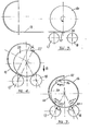
- plate rolling apparatus comprising a horizontal framework 11 embodying supporting rollers 12 or other like means upon which steel or other plate 13 may be advanced horizontally at a convenient height.
- the framework 11 has a well 14 through which a massive supporting I-beam 15 extends in a direction at right-angles to the direction of advancement of the plate 13 with its flanges horizontal.
- the upper flange 16 supports two horizontal rollers 17 and 18 the axes of which extend in the longitudinal direction of the I-beam 15 at an appropriate height for the upper surface of the rollers 17 and 18 to be at the same height as the upper surfaces of the rollers 12.
- flat plate advanced along the rollers 12 also contacts and runs upon the rollers 17 and 18.
- rollers 17 and 18 are sufficiently great to engage the full width of the plate 13.
- the rollers 17 and 18 are shown supported by end brackets 19 fixed on the flange 16 and it is to be understood that as many intermediate supporting brackets may be provided along the rollers 17 and 18 as are deemed necessary to prevent significant flexing.
- the flange 16 is provided with means for supporting a mandrel 20 with its axis above the web of the I-beam 15 centrally spaced between the rollers 17 and 18 but above them.
- the supporting means comprises two hydraulic cylinders 21 and 22.
- One cylinder 21 is fixed in position with a shaft bearing 23 mounted on the upper end of its piston rod 24.
- the other cylinder 22 also has a piston rod 25 with a shaft bearing 26 mounted on its end, but instead of being fixed to the flange 16 it is connected by a pivot pin 27 to a bracket 28 fixed on the flange 16.
- the cylinder 22 is pivotally connected to the piston rod 29 of a further hydraulic cylinder 30 pivoted to the web of the I-beam 15 so that by retraction of the piston rod 29 into the cylinder 30 the cylinder 22 together with its piston rod 25 and bearing 26 can be swung downwardly from the full line position shown in Figure 2 into the position shown in dotted lines in which it is entirely below the path of movement of the plate 13.
- cylinder 22 With the cylinder 22 in its erect position shown in full lines in Figure 2, its bearing 26 and the bearing 23 provide support for the shaft 31 of the mandrel. Mandrels of different diameters can be used with appropriate raising or lowering of the piston rods 24 and 25.
- Suitable drive means is provided for the shaft 31 comprising a motor 32 and reduction and reversing gear box 33, both mounted on the I-beam 15 with a double universal drive connection 34 extending from the gear box 33 to the shaft 31.
- FIGS 3 to 5 show schematically the various stages of completion of formation of a pipe according to the present invention using the apparatus described in Figures 1 to 2.
- the torque applied to the mandrel which is constant for practically the full forming cycle, and equal to the plastic moment (MPL) of the plate 13, is in fact applied to the plate edge via the gripper 36.
- the mandrel 20 acts as guide and there is contact but little pressure between the mandrel 20 and the plate 13. Whilst the plate is in contact with the mandrel there exists all around the plate a bending moment equal to the plastic moment (MPL).
- the opposing moments are generated by lowering the mandrel by operation of power cylinders 21, 22 in the direction of arrow B or raising the rollers (by means not shown) until both rollers are engaged by the plate thereby creating lateral forces Fr 1 and Fr 2 .
- the action of the forces creates a horizontal component of force HFr 2 and HFr 2 , which give rise to these opposing moments.
Landscapes
- Engineering & Computer Science (AREA)
- Mechanical Engineering (AREA)
- Bending Of Plates, Rods, And Pipes (AREA)
Priority Applications (1)
| Application Number | Priority Date | Filing Date | Title |
|---|---|---|---|
| AT80304061T ATE7274T1 (de) | 1979-11-15 | 1980-11-13 | Verfahren und apparat zum walzen von blech zum herstellen eines im wesentlichen zylindrischen gegenstandes. |
Applications Claiming Priority (2)
| Application Number | Priority Date | Filing Date | Title |
|---|---|---|---|
| AU1342/79 | 1979-11-15 | ||
| AUPE134279 | 1979-11-15 |
Publications (3)
| Publication Number | Publication Date |
|---|---|
| EP0029345A2 true EP0029345A2 (fr) | 1981-05-27 |
| EP0029345A3 EP0029345A3 (en) | 1981-11-04 |
| EP0029345B1 EP0029345B1 (fr) | 1984-05-02 |
Family
ID=3768336
Family Applications (1)
| Application Number | Title | Priority Date | Filing Date |
|---|---|---|---|
| EP80304061A Expired EP0029345B1 (fr) | 1979-11-15 | 1980-11-13 | Procédé et dispositif pour le cintrage arrondi de tôle d'un article essentiellement cylindrique |
Country Status (9)
| Country | Link |
|---|---|
| EP (1) | EP0029345B1 (fr) |
| JP (1) | JPS56111524A (fr) |
| AR (1) | AR225199A1 (fr) |
| AT (1) | ATE7274T1 (fr) |
| BR (1) | BR8007426A (fr) |
| CA (1) | CA1138761A (fr) |
| NZ (1) | NZ195554A (fr) |
| PH (1) | PH23274A (fr) |
| ZA (1) | ZA807076B (fr) |
Cited By (12)
| Publication number | Priority date | Publication date | Assignee | Title |
|---|---|---|---|---|
| EP0049079A1 (fr) * | 1980-09-19 | 1982-04-07 | Kenneth Michael Hume | Procédé pour le cintrage de tôle |
| EP0182868A4 (fr) * | 1984-05-16 | 1986-09-04 | Kaiser Steel Corp | Procede et appareil de laminage de tuyaux. |
| WO1994022608A1 (fr) * | 1993-04-05 | 1994-10-13 | Kenneth Michael Hume | Machine a former des tuyaux |
| ITMI20091174A1 (it) * | 2009-07-02 | 2011-01-03 | Marco Zambolin | Procedimento di realizzazione di moduli di canalizzazione per impianti di distribuzione di aria e condotto ottenuto mediante tale procedimento |
| ITMI20111380A1 (it) * | 2011-07-25 | 2013-01-26 | Marco Zambolin | Procedimento di realizzazione di moduli di canalizzazione per impianti di distribuzione di aria e condotto ottenuto mediante tale procedimento |
| ITMI20111384A1 (it) * | 2011-07-25 | 2013-01-26 | Marco Zambolin | Procedimento di realizzazione di moduli di canalizzazione per impianti di distribuzione di aria e condotto ottenuto mediante tale procedimento |
| ITMI20111382A1 (it) * | 2011-07-25 | 2013-01-26 | Marco Zambolin | Procedimento di realizzazione di moduli di canalizzazione per impianti di distribuzione di aria e condotto ottenuto mediante tale procedimento |
| CN104690431A (zh) * | 2015-01-22 | 2015-06-10 | 安徽万嘉新能源科技有限公司 | 一种带有激光切割装置的太阳能热水器加工设备 |
| CN105013890A (zh) * | 2015-07-29 | 2015-11-04 | 成都市松川金属材料有限公司 | 一种方便送料的卷圆机 |
| TWI610778B (zh) * | 2016-10-27 | 2018-01-11 | 宜營機械有限公司 | 板材輾壓機 |
| CN111318596A (zh) * | 2020-03-25 | 2020-06-23 | 江门市腾宏金属制品有限公司 | 一种不锈钢管制管机 |
| CN117181873A (zh) * | 2023-10-25 | 2023-12-08 | 四川烨晶化工装备有限公司 | 一种弯管装置 |
Family Cites Families (8)
| Publication number | Priority date | Publication date | Assignee | Title |
|---|---|---|---|---|
| DE7122636U (de) * | 1972-12-21 | Mori Masuri | Stahlblechbiegevorrichtung | |
| DE618901C (de) * | 1933-12-23 | 1935-09-20 | Wilhelm Heinen | Vorrichtung zum Biegen von Blechstreifen o. dgl., insbesondere zu mehr oder weniger g eschlossenen Roehren |
| GB1099191A (en) * | 1963-12-19 | 1968-01-17 | Scottish Machine Tool Corp Ltd | Improvements in or relating to plate bending machines |
| FR1553901A (fr) * | 1967-11-29 | 1969-01-17 | ||
| DE1752666C3 (de) * | 1968-06-29 | 1975-09-25 | Wilhelmsburger Maschinenfabrik, Hinrichs & Sohn, 2054 Geesthacht | Blechplattenbiegemaschine |
| FR2097182A7 (en) * | 1970-07-04 | 1972-03-03 | Ferranti Albino | Sheet metal cylinders - bending of long lengths |
| US3738149A (en) * | 1971-10-01 | 1973-06-12 | B Archer | Pipe forming apparatus and method |
| US3879994A (en) * | 1973-08-16 | 1975-04-29 | Kenneth Michael Hume | Plate rolling |
-
1980
- 1980-11-13 AT AT80304061T patent/ATE7274T1/de not_active IP Right Cessation
- 1980-11-13 BR BR8007426A patent/BR8007426A/pt not_active IP Right Cessation
- 1980-11-13 EP EP80304061A patent/EP0029345B1/fr not_active Expired
- 1980-11-14 PH PH24858A patent/PH23274A/en unknown
- 1980-11-14 JP JP16064380A patent/JPS56111524A/ja active Granted
- 1980-11-14 NZ NZ195554A patent/NZ195554A/en unknown
- 1980-11-14 ZA ZA00807076A patent/ZA807076B/xx unknown
- 1980-11-14 CA CA000364652A patent/CA1138761A/fr not_active Expired
- 1980-11-17 AR AR283262A patent/AR225199A1/es active
Cited By (14)
| Publication number | Priority date | Publication date | Assignee | Title |
|---|---|---|---|---|
| EP0049079A1 (fr) * | 1980-09-19 | 1982-04-07 | Kenneth Michael Hume | Procédé pour le cintrage de tôle |
| EP0182868A4 (fr) * | 1984-05-16 | 1986-09-04 | Kaiser Steel Corp | Procede et appareil de laminage de tuyaux. |
| WO1994022608A1 (fr) * | 1993-04-05 | 1994-10-13 | Kenneth Michael Hume | Machine a former des tuyaux |
| GB2291609A (en) * | 1993-04-05 | 1996-01-31 | Kenneth Michael Hume | Pipe forming machine |
| ITMI20091174A1 (it) * | 2009-07-02 | 2011-01-03 | Marco Zambolin | Procedimento di realizzazione di moduli di canalizzazione per impianti di distribuzione di aria e condotto ottenuto mediante tale procedimento |
| WO2011001279A1 (fr) * | 2009-07-02 | 2011-01-06 | Marco Zambolin | Procédé pour réaliser des modules de canalisations dinstallations de distribution dair, module de canalisation, et procédé demballage et procédé dassemblage desdits modules |
| ITMI20111380A1 (it) * | 2011-07-25 | 2013-01-26 | Marco Zambolin | Procedimento di realizzazione di moduli di canalizzazione per impianti di distribuzione di aria e condotto ottenuto mediante tale procedimento |
| ITMI20111384A1 (it) * | 2011-07-25 | 2013-01-26 | Marco Zambolin | Procedimento di realizzazione di moduli di canalizzazione per impianti di distribuzione di aria e condotto ottenuto mediante tale procedimento |
| ITMI20111382A1 (it) * | 2011-07-25 | 2013-01-26 | Marco Zambolin | Procedimento di realizzazione di moduli di canalizzazione per impianti di distribuzione di aria e condotto ottenuto mediante tale procedimento |
| CN104690431A (zh) * | 2015-01-22 | 2015-06-10 | 安徽万嘉新能源科技有限公司 | 一种带有激光切割装置的太阳能热水器加工设备 |
| CN105013890A (zh) * | 2015-07-29 | 2015-11-04 | 成都市松川金属材料有限公司 | 一种方便送料的卷圆机 |
| TWI610778B (zh) * | 2016-10-27 | 2018-01-11 | 宜營機械有限公司 | 板材輾壓機 |
| CN111318596A (zh) * | 2020-03-25 | 2020-06-23 | 江门市腾宏金属制品有限公司 | 一种不锈钢管制管机 |
| CN117181873A (zh) * | 2023-10-25 | 2023-12-08 | 四川烨晶化工装备有限公司 | 一种弯管装置 |
Also Published As
| Publication number | Publication date |
|---|---|
| CA1138761A (fr) | 1983-01-04 |
| BR8007426A (pt) | 1981-05-26 |
| EP0029345A3 (en) | 1981-11-04 |
| NZ195554A (en) | 1984-10-19 |
| AR225199A1 (es) | 1982-02-26 |
| PH23274A (en) | 1989-06-23 |
| JPS56111524A (en) | 1981-09-03 |
| ZA807076B (en) | 1981-11-25 |
| EP0029345B1 (fr) | 1984-05-02 |
| JPS6321570B2 (fr) | 1988-05-07 |
| ATE7274T1 (de) | 1984-05-15 |
Similar Documents
| Publication | Publication Date | Title |
|---|---|---|
| EP0029345A2 (fr) | Procédé et dispositif pour le cintrage arrondi de tôle d'un article essentiellement cylindrique | |
| US3879994A (en) | Plate rolling | |
| US4706488A (en) | Method of roll forming cylindrical pipe | |
| JPH0379082B2 (fr) | ||
| US3461703A (en) | Apparatus for uncoiling and processing metal strip | |
| US5245849A (en) | Apparatus for forming a pipe from a sheet metal plate | |
| US4406141A (en) | Straightening apparatus for steel pipes and the like | |
| US4606208A (en) | Pipe forming apparatus | |
| EP0035483A2 (fr) | Méthode de cintrage d'une tôle ondulée et appareil mettant en oeuvre cette méthode | |
| US4628721A (en) | Method of roll forming cylindrical pipe | |
| CN211613912U (zh) | 一种自动翻边卷板机 | |
| CN220501110U (zh) | 一种具有调节功能的钢管包装机 | |
| SU1119602A3 (ru) | Способ гибки-прокатки толстого листа и устройство дл гибки-прокатки толстого листа | |
| CN205571068U (zh) | 薄壁板材卷圆设备 | |
| AU634220B2 (en) | Apparatus for forming a pipe from a sheet metal plate | |
| JPH01104419A (ja) | 管端部変形矯正装置 | |
| CN219899733U (zh) | 楔横轧轴件矫直装置 | |
| DE1777354C3 (de) | Bördelmaschine zur Kalt- und/ oder Warmumformung des Bordrandes flacher oder gewölbter Behälterboden. Ausscheidung aus: 1777251 | |
| CN222856445U (zh) | 一种汽车生产用钢板冲孔装置 | |
| CN2153423Y (zh) | 油压传动式大尺寸轮管机 | |
| CN212884280U (zh) | 一种带导向装置的卷板机 | |
| JPH0970622A (ja) | ロール曲げ方法及びその方法を実施する装置 | |
| JP7656573B2 (ja) | ベンディングロール | |
| US3602029A (en) | Roll forming assembly | |
| CN119346666B (zh) | 一种热轧板材用精密多辊矫直机 |
Legal Events
| Date | Code | Title | Description |
|---|---|---|---|
| PUAI | Public reference made under article 153(3) epc to a published international application that has entered the european phase |
Free format text: ORIGINAL CODE: 0009012 |
|
| AK | Designated contracting states |
Designated state(s): AT BE CH DE FR GB IT LU NL SE |
|
| PUAL | Search report despatched |
Free format text: ORIGINAL CODE: 0009013 |
|
| AK | Designated contracting states |
Designated state(s): AT BE CH DE FR GB IT LU NL SE |
|
| RHK1 | Main classification (correction) |
Ipc: B21C 37/08 |
|
| 17P | Request for examination filed |
Effective date: 19820419 |
|
| ITF | It: translation for a ep patent filed | ||
| GRAA | (expected) grant |
Free format text: ORIGINAL CODE: 0009210 |
|
| AK | Designated contracting states |
Designated state(s): AT BE CH DE FR GB IT LI LU NL SE |
|
| REF | Corresponds to: |
Ref document number: 7274 Country of ref document: AT Date of ref document: 19840515 Kind code of ref document: T |
|
| REF | Corresponds to: |
Ref document number: 3067712 Country of ref document: DE Date of ref document: 19840607 |
|
| ET | Fr: translation filed | ||
| PLBE | No opposition filed within time limit |
Free format text: ORIGINAL CODE: 0009261 |
|
| STAA | Information on the status of an ep patent application or granted ep patent |
Free format text: STATUS: NO OPPOSITION FILED WITHIN TIME LIMIT |
|
| 26N | No opposition filed | ||
| ITTA | It: last paid annual fee | ||
| EPTA | Lu: last paid annual fee | ||
| EAL | Se: european patent in force in sweden |
Ref document number: 80304061.7 |
|
| PGFP | Annual fee paid to national office [announced via postgrant information from national office to epo] |
Ref country code: GB Payment date: 19971104 Year of fee payment: 18 |
|
| PGFP | Annual fee paid to national office [announced via postgrant information from national office to epo] |
Ref country code: DE Payment date: 19971121 Year of fee payment: 18 |
|
| PGFP | Annual fee paid to national office [announced via postgrant information from national office to epo] |
Ref country code: SE Payment date: 19981105 Year of fee payment: 19 |
|
| PGFP | Annual fee paid to national office [announced via postgrant information from national office to epo] |
Ref country code: FR Payment date: 19981110 Year of fee payment: 19 |
|
| PGFP | Annual fee paid to national office [announced via postgrant information from national office to epo] |
Ref country code: AT Payment date: 19981112 Year of fee payment: 19 |
|
| PG25 | Lapsed in a contracting state [announced via postgrant information from national office to epo] |
Ref country code: GB Free format text: LAPSE BECAUSE OF NON-PAYMENT OF DUE FEES Effective date: 19981113 |
|
| PGFP | Annual fee paid to national office [announced via postgrant information from national office to epo] |
Ref country code: CH Payment date: 19981120 Year of fee payment: 19 |
|
| PGFP | Annual fee paid to national office [announced via postgrant information from national office to epo] |
Ref country code: NL Payment date: 19981126 Year of fee payment: 19 |
|
| PGFP | Annual fee paid to national office [announced via postgrant information from national office to epo] |
Ref country code: LU Payment date: 19981214 Year of fee payment: 19 |
|
| PGFP | Annual fee paid to national office [announced via postgrant information from national office to epo] |
Ref country code: BE Payment date: 19990119 Year of fee payment: 19 |
|
| GBPC | Gb: european patent ceased through non-payment of renewal fee |
Effective date: 19981113 |
|
| PG25 | Lapsed in a contracting state [announced via postgrant information from national office to epo] |
Ref country code: DE Free format text: LAPSE BECAUSE OF NON-PAYMENT OF DUE FEES Effective date: 19990901 |
|
| PG25 | Lapsed in a contracting state [announced via postgrant information from national office to epo] |
Ref country code: LU Free format text: LAPSE BECAUSE OF NON-PAYMENT OF DUE FEES Effective date: 19991113 Ref country code: AT Free format text: LAPSE BECAUSE OF NON-PAYMENT OF DUE FEES Effective date: 19991113 |
|
| PG25 | Lapsed in a contracting state [announced via postgrant information from national office to epo] |
Ref country code: SE Free format text: LAPSE BECAUSE OF NON-PAYMENT OF DUE FEES Effective date: 19991114 |
|
| PG25 | Lapsed in a contracting state [announced via postgrant information from national office to epo] |
Ref country code: LI Free format text: LAPSE BECAUSE OF NON-PAYMENT OF DUE FEES Effective date: 19991130 Ref country code: CH Free format text: LAPSE BECAUSE OF NON-PAYMENT OF DUE FEES Effective date: 19991130 Ref country code: BE Free format text: LAPSE BECAUSE OF NON-PAYMENT OF DUE FEES Effective date: 19991130 |
|
| BERE | Be: lapsed |
Owner name: HUME KENNETH MICHAEL Effective date: 19991130 |
|
| PG25 | Lapsed in a contracting state [announced via postgrant information from national office to epo] |
Ref country code: NL Free format text: LAPSE BECAUSE OF NON-PAYMENT OF DUE FEES Effective date: 20000601 |
|
| REG | Reference to a national code |
Ref country code: CH Ref legal event code: PL |
|
| EUG | Se: european patent has lapsed |
Ref document number: 80304061.7 |
|
| PG25 | Lapsed in a contracting state [announced via postgrant information from national office to epo] |
Ref country code: FR Free format text: LAPSE BECAUSE OF NON-PAYMENT OF DUE FEES Effective date: 20000731 |
|
| NLV4 | Nl: lapsed or anulled due to non-payment of the annual fee |
Effective date: 20000601 |
|
| REG | Reference to a national code |
Ref country code: FR Ref legal event code: ST |