EP0035483A2 - Méthode de cintrage d'une tôle ondulée et appareil mettant en oeuvre cette méthode - Google Patents
Méthode de cintrage d'une tôle ondulée et appareil mettant en oeuvre cette méthode Download PDFInfo
- Publication number
- EP0035483A2 EP0035483A2 EP81850033A EP81850033A EP0035483A2 EP 0035483 A2 EP0035483 A2 EP 0035483A2 EP 81850033 A EP81850033 A EP 81850033A EP 81850033 A EP81850033 A EP 81850033A EP 0035483 A2 EP0035483 A2 EP 0035483A2
- Authority
- EP
- European Patent Office
- Prior art keywords
- bending
- sheet
- ridges
- shaped
- valleys
- Prior art date
- Legal status (The legal status is an assumption and is not a legal conclusion. Google has not performed a legal analysis and makes no representation as to the accuracy of the status listed.)
- Ceased
Links
Images


Classifications
-
- B—PERFORMING OPERATIONS; TRANSPORTING
- B21—MECHANICAL METAL-WORKING WITHOUT ESSENTIALLY REMOVING MATERIAL; PUNCHING METAL
- B21D—WORKING OR PROCESSING OF SHEET METAL OR METAL TUBES, RODS OR PROFILES WITHOUT ESSENTIALLY REMOVING MATERIAL; PUNCHING METAL
- B21D11/00—Bending not restricted to forms of material mentioned in only one of groups B21D5/00, B21D7/00, B21D9/00; Bending not provided for in groups B21D5/00 - B21D9/00; Twisting
- B21D11/20—Bending sheet metal, not otherwise provided for
- B21D11/206—Curving corrugated sheets
-
- B—PERFORMING OPERATIONS; TRANSPORTING
- B21—MECHANICAL METAL-WORKING WITHOUT ESSENTIALLY REMOVING MATERIAL; PUNCHING METAL
- B21D—WORKING OR PROCESSING OF SHEET METAL OR METAL TUBES, RODS OR PROFILES WITHOUT ESSENTIALLY REMOVING MATERIAL; PUNCHING METAL
- B21D11/00—Bending not restricted to forms of material mentioned in only one of groups B21D5/00, B21D7/00, B21D9/00; Bending not provided for in groups B21D5/00 - B21D9/00; Twisting
- B21D11/08—Bending by altering the thickness of part of the cross-section of the work
-
- B—PERFORMING OPERATIONS; TRANSPORTING
- B21—MECHANICAL METAL-WORKING WITHOUT ESSENTIALLY REMOVING MATERIAL; PUNCHING METAL
- B21D—WORKING OR PROCESSING OF SHEET METAL OR METAL TUBES, RODS OR PROFILES WITHOUT ESSENTIALLY REMOVING MATERIAL; PUNCHING METAL
- B21D11/00—Bending not restricted to forms of material mentioned in only one of groups B21D5/00, B21D7/00, B21D9/00; Bending not provided for in groups B21D5/00 - B21D9/00; Twisting
- B21D11/20—Bending sheet metal, not otherwise provided for
Definitions
- This invention relates to a method of bending shaped or corrugated metal sheet, which has alternatingly occurring longitudinal ridges and valleys, the side portions of which also constitute,the side portions of the ridges, about an axis, which extends perpendicularly to the longitudinal direction of the ridges and valleys and is in parallel with the plane of the metal sheet.
- the invention further relates to an apparatus for carrying out the method.
- the present inventiqn therefore, has the object a.o. to provide a bending method, which can be applied to substantially all existing types of shaped or corrugated metal sheet, and which renders possible the bending of such shaped sheet up to at least 90° in one step or bending moment, and which, besides, shall be careful to the sheet and not weaken it to an appreciable degree at and about the place of bending.
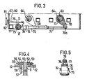
- the apparatus according to the present invention for bending corrugated metal sheet comprises a bending or pressing frame which consists of a stand 2 and is provided with a bending tool generally designated by 3.
- This tool is assembled of several parts, viz. a punch 3a, which by screw or bolt joint 4 is detachably, and thus exchangeably, secured on an upper vertically movable tool holder 5, and three dies 3b, 3c, of which the one designated by 3b by a screw or bolt joint 6 is detachably connected to a plate 7, which as an anvil or dolly is rigidly secured in the stand 2, while the two remaining dies 3c by screw or bolt joints 8 are connected each to a lower tool holder 9, which are provided on each side of the anvil plate 7 and each are movable in a plane 10 forming an angle ⁇ with the anvil plate 7.
- This angle X can be between 10 and 50° and should preferably be about 30°, as shown at the embodiment illustrated in the drawings.
- the upper tool holder 5 is a plate 11, to the lower edge of which the punch 3a is detachably attached, and which extends between end walls 12 of the stand. At these end walls the plate 11,.by means of slide strips 13 attached to its ends, is movably guided between parallel guide strips 15, which by means of screws 14 are connected to the end walls 12 and are adjustable by means of set screws 16 provided in bars 17 attached to the end walls 12. In order to prevent the plate 11 from moving in its longitudinal direction between the end walls 12, the plate is provided at each end with guide rollers 180 co-operating with the guide strips 15.
- the tool holder plate 11 is suspended on two spaced links 18, each of which consists of two parallel parts, which are connected to the plate 11 each by its axle 19.
- Ech axle 19 is rotatably mounted in the plate 11 by means of bearings 20 located between the parts of the respective link.
- each link 18 is connected to an axle 21, which is rotatably mounted each in a swinging arm 22 through a bearing 23 located with the parts of the respective link.
- the axles 21 of the two swinging arms are interconnected through a parallel guide rod 24 consisting of two parallel parts and like the axles 19 are provided at each end with washers 25 and locking rings 26, which-fix the axles against movement in axial direction.
- Each swinging arm 23 is rotatably suspended on an eccentric axle 27, which by axle journals 28 are rotatably mounted in bearings 29, with bearing holders 30 secured by screws in the upper sidewalls 31 of the stand.
- One of said swinging arms 22 is formed at one end with a stop shoulder 32, which in co-operation with a stud 33 provided in the associated link 18 between the parts thereof limits the clockwise movement of the swinging arm to the position shown in Fig. 2, and at its other end is formed with a fastening lug 34 for a piston-cylinder device 35, which operates between said fastening lug and the stand 2 for swinging the swinging arms 22.
- the swinging arm 22 connected to the piston rod is swung counter-clockwise about the centre point 37 of the eccentric axle, and to a corresponding degree also the other swinging arm is swung about its axis, due to the parallel guide bar 24, whereby also the tool holder plate 11 with the punch 3a is lifted from the position of preparedness for bending to an upper starting position for obatining a relatively large gap between the upper and the lower tool parts.
- the piston rod 3a of the piston-cylinder device is caused to move in opposite direction and thereby swings the swinging arms 22 clockwise until the stop shoulder 32 meshes with the stud 33, whereby said position of preparedness has been obtained. Due to the piston-cylinder device 35 acting directly on one swinging arm 22, the lowering and lifting of the plate 11, and therewith of the punch 3a, takes place rapidly between the starting position and the position of preparedness.
- a piston-cylinder device 38 For lowering the tool holder plate 11 with its punch 3a from the position of preparedness to a bending position, and for effecting necessary bending or pressing forces for bending corrugated metal sheet inserted between the punch 3a and the die 3b, a piston-cylinder device 38 is provided. This' device is hingedly attached at one end to the stand 2; and its piston rod 39 is rotatably mounted by means of a journal 40 and a. bearing 41 in a rotary lug 42, which is rigidly connected with one eccentric axle 27.
- an additional rotary lug 43 is fastened, which is connected to a corresponding rotary lug 44 mounted on the other eccentric axle 27 through a link rod 45, which preferably is adjustable as to its length and at its ends is rotatably mounted in the respective rotary lug by means of journals 46 and bearings 47.
- this link rod 45 thus, the eccentric axles are rotated simultaneously and to the same extent about the respective rotary axles 48.
- the two eccentric axles Upon projecting the piston rod 39 of the piston-cylinder device in the position of preparedness shown in Fig. 1, the two eccentric axles, thus, are rotated simultaneously about the respective rotary axle 48 and thereby through their ecc- entrics 49 cause the swinging arms 22 together with the links 18 and the tool holder 5 to be moved downward to the bending position with the force required for bending a sheet to a predetermined angle by co-operation of the punch with the stationary die 3b.
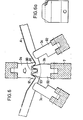
- the movable dies 3c are in a retracted position, as shown in Fig. 6.
- the piston-cylinder device 35 During the bending phase, i.e. during the movement of the punch 3a to and from the bending position, the piston-cylinder device 35 is in floating position, so that its piston rod 36 can move freely.
- Each of the lower tool holder plates 9 carrying the dies 3c which plates are arranged identically each in a lower part 50 of the stand, extends outward through openings 51 in the end walls 12 of the stand and is provided at its ends with slide strips 52, by means of which they are movably guided between parallel guide strips 54 attached by screws 53 to the end walls 12. Said guide strips are adjustable by means of set screws 55 located on bars 56 attached to the end walls.
- the tool holder plate 9 In order to prevent the tool holder plate 9 from moving in its longitudinal direction between the end walls 12, it is provided with at least one guide roller 57 at each end, which rollers co-operate with a guide bar 58 attached to the inside of the end wall, possibly by means of the same screws 53, which are used for attaching the guide strip 54 located on the outside of the end wall.
- Each tool holder 9 formed as a plate carries two spaced links 60, each of which is hingedly connected to the plate 9 by means of a stud 61 and a bearing 62, and at its other end is rotatably mounted each on an eccentric axle 63, which by means of their axle journals 64 are mounted in bearings 55 in bearing holders 66 secured by screws in the sidewalls 67 of the stand.
- the two eccentric axles 63 are provided each with a rotary lug 68, and these lugs 68, which are rigidly connected to the axles 63, are interconnected by a link rod 69 for effecting simultaneous rotation of the two axles 63.
- One of said axles further is provided with an additional rotary lug 70, in which a piston rod of a piston-cylinder device 72 hingedly attached to the stand 2 is hingedly attached by means of a stud 70a.
- the eccentric axles 63 about their centre of rotation 73 and thereby for lifting and lowering the tool holder 9 in response to the movement of the upper tool holder 9 to and from the bending position, the piston-cylinder devices 72 of the two tool holders 9 are synchronized with one another, so that the movement of the tool holders, and therewith of the dies 3c, to and from bending position takes place simultaneously.
- each piston-cylinder device is connected at its end remote from the piston rod 71 to a cylinder mounting 74, which is located on an axle 75.
- Said axle 75 is located eccentrically within a greater axle 76, which is mounted in brackets 77 attached to the stand.
- a rotary lug 78 connected non-rotary to the axle 76 is provided which rotatably carries a stud 79 with a threaded hole, into which a threaded adjusting rod 80 is screwn.
- Said rod extends through the stand wall 67 and outside of this is provided with a wheel 81 and is rotatably mounted in the wall 57 through a bearing bushing 82,
- the rotary lug 78 rotates the axle 76, and thereby the axle 75 eccentrically located therein, and therewith said cylinder mounting 74, are moved in one direction or the other, depending on whether the rod is rotated clockwise or counter-clockwise. It is thereby possible to adjust the rotary lugs 68 connected to the eccentric axles 63 to the desired angular position for obtaining the intended bending position for the dies 3c, i.e. their upper end position. This end position, however, is adjustable in vertical direction and by changing this upper end position it is also possible to change the angle to which the sheet is to be bent. The greater the desired bending angle, the higher the upper end position is located.
- the end positions of the movable dies also can be determined, for example, by stationary guide members 84,85.
- arms 86,87 are provided which are connected to the axle journal 64 of one eccentric axle and adjustable relative to each other.
- the arm 86 has contacted the guide member 84, which thereby causes the piston-cylinder devices 72 to change the direction of movement in order to lower the dies 3c, and when the lower end position has been assumed the arm.
- 87 actuates the guide member 85, which thereby causes the piston-cylinder devices 72 to remain in this position and to wait for a starting impulse.
- the tool 3 comprises an upper punch 3a, which has three downward projecting fingers 90 and 91, which in strip shape extend over the entire length of the punch and therewith over the entire width of the sheet to be bent.
- the central finger 90 thereof is located in the plane of vertical movement of the punch, while the remaining two fingers 91 are located angularly relative to the central one, which angle can vary from one case to another, but preferably should correspond to the angle between the plane of movement 10 of the dies and that of the punch.
- the tool further comprises the dies 3b and 3c, each of which has at least the same length as the punch 3a, and which show support members or teeth 92 and recesses therebetween, which alternate in a way corresponding to the ridges and valleys or corrugations of the shaped sheet to be bent.
- the support members 92 may have the lateral form shown in Fig. 6a, i.e. a form adapted to the cross-sectional form of the ridges and valleys.
- the cross--sectional form of the support members of the dies is as shown in Figs. 6 and 7.
- the bending is carried out in two subsequent steps.
- the punch 3a is moved from its position of preparedness to the bending position, which.is shown in Fig. 6, and in which the punch with its central finger 90 projecting through a longer distance than the two outer fingers 91 has effected an impression in those portions of the sheet A inserted between.the punch 3a and the dies 3b and 3c which are facing to the punch 3a.
- Said impression is located between the projections 93 of the support members 92, which projections are upwardly rounded--off.
- the punch With its outer fingers 91 the punch has effected slightly less deep impressions on both sides of the impression made by the finger 90.
- the sheet A thereby has been bent partially.
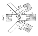
- the movable lateral dies 3c are caused to project upward on the outside of the outer fingers 91 of the punch, but first after the punch 3a has completed its movement stroke and clamps the sheet against the die 3b. Said dies 3c thereby bend the sheet A about the fingers 91 of the punch.and, thus, complete the bending of the sheet to the desired angle, as shown in Fig. 7, where the bending angle is 90°.
- the bending angle is 90°.
- other bending angles can be obtained.
- each such stripper is shown to comprise a carrying beam 96, which extends between the end walls 12 of the stand, and which at its ends is attached to swinging arms 97, which are connected pivotally each with an arm 98, which are attached to a bracket 99 secured by screws in the respective end wall 1'2.
- a number-of bogie wheels 100 acting as dollies are suspended by means of mountings 101, in which the bogie wheels are freely pivotal.
- rotary sheet holders 102 are provided, which are rotated by a motor 103.
- the carrying beam 96 is supported on a piston-cylinder device 104, which is hingedly attached to the upper sidewall 31 of the stand, and by means of which the carrying beam 96 can be pivoted about the swinging centre 105 of the swinging arms 97.
- the sheet is pivoted upward by the movable dies 3c and thereby, contacts the bogie wheels 100, which thereby adjust after the sheet A. Thereafter the motors 103 pivot the sheet holders 102 below the edges of the sheet and clamp the sheet A against the bogie wheels 100. The sheet thereby is locked in the stripper 95, When then the upper punch 3a returns to its position of preparedness, the sheet is released automatically from the punch 3a. By means of the piston-cylinder device 104 the sheet then can be pivoted downward and placed on a conveyor (not shown in Figs. 8 and 9) for being advanced through the bending frame, whereafter the stripper automatically returns to its starting position shown in Fig. 8 for handling the next sheet.
- a conveyor not shown in Figs. 8 and 9
- a plant for manufacturing pallets is shown schematically.
- blanks of corrugated sheet metal and preferably trapezoid corrugated sheet metal cut to a suitable length are bent.
- the plant comprises, in addition to a bending frame 110 according to the invention, a supply table 111 with a supply of cut to size sheet metal blanks 112, an infeed table 113 and a discharge table 114.
- a magnetic lifting device 116 which is movable along guide means 115 and tranfers the sheet blank to the infeed table 113, whereafter the lifting device returns for fetching the next sheet blank.
- the sheet blank On the infeed table the sheet blank is carried on roller conveyors 117 and guided by a guide bar 119 provided with rollers 118 while it is advanced by means cf dog members 120, which by a cross-rod 121 are connected to two cylinders 122, preferably so-called Origa-cylinders. acting as drive means.
- a number of carrying bars 123 are provided, which are hingedly attached to the infeed table and are carried by the stationary die 3b in recesses between the supporting members 92 thereof for guiding the sheet into correct position in the bending frame.
- the discharge table 114 shown in greater detail in Figs. 13 and 14 comprises two conveyor belts 128, which are driven by a worm gear motor 125 via a shaft 126 and elastic coupling 127.
- Each conveyor belt 128 is provided with a belt stretcher 129, a guide bar 131 provided with rollers 130 for guiding the sheet, and a movable sheet stop member 132 adjustable in different positions and moved to the different positions by means of a cylinder.133, preferably pneumatic and of Origa- type Said cylinder 133 is supported on a cylinder stand 134 with mounting plates 135, and the stand in its turn is supported on links 137 hingedly attached to the table frame by axles 136.
- Said links also are hingedly attached to the mounting plates 135 of the cylinder stand by means of axles 139 mounted in bearing bushings 138.
- a piston-cylinder device 140 preferably pneumatic or hydraulic, is provided between the table frame and the cylinder stand 134 for lifting and lowering the cylinder stand 134 and therewith a stop member 141, which is located at the stand end facing to the bending frame 110.
- a number of clamping tools 142 and a number of limit switches (not shown) for the different positions of the movable stop member 132 are also provided.
- the bending frame is started again and carries out its bending operation for effecting a second bending of the sheet blank through 90°, as shown at 145 in Fig. 15b.
- the movable stop member 132 moves to a rear end position , and the sheet blank 112 is advanced against said stop member, whereafter the sheet blank is bent through 90° at its other end as shown at 146 in Fig. 15c.
- the sheet blank is moved in the opposite direction by the stop member 132 to a new position, in which the sheet blank is bent through 90° inside of the bending 146 effected last, as shown at 147 in Fig. 15d.
- the sheet blank has been bent four times and formed to a pallet.
- the punch 3a For rendering it possible to remove the pallet from the bending frame 110, the punch 3a must be lifted to the said starting position. This lifting is effected by the piston--cylinder device 35.
- Figs. 16a-e a similar bending sequence as the one shown in Figs. 15a-d is illustrated, but in this case for producing a pallet of type other than that shown in Figs. 15a-d, as supporting legs.
- the sheet blank is bent at first through 45°, as shown in Fig. 16a at 151, then advanced through one step and bent through 45°, as shown in Fig. 16b at 152, then advanced through a further step and bent through 90°, as shown in Fig. 16c at 153, and then advanced through a long step to be bent at its other edge through 45 0 , as shown in Fig. 16d at 154. Thereafter the sheet blank is fed in the opposite direction through one step and bent through 45°, as shown at 155 in Fig. 16d, and finally it is advanced through a further step in the same direction to be bent through 90°, as shown at 156 in Fig. 16d.
- the edge portions 150 now can be folded inward by means of a pressure bar 161 pivotal about an axle 160 to the position shown'in Fig. 16e.
- the pallet abuts a support 161 as shown schematically in Fig. 16e.
Landscapes
- Engineering & Computer Science (AREA)
- Mechanical Engineering (AREA)
- Bending Of Plates, Rods, And Pipes (AREA)
- Electrical Discharge Machining, Electrochemical Machining, And Combined Machining (AREA)
- Crushing And Grinding (AREA)
Applications Claiming Priority (2)
| Application Number | Priority Date | Filing Date | Title |
|---|---|---|---|
| SE8001670A SE431519B (sv) | 1980-03-04 | 1980-03-04 | Sett att bocka profilerad plat samt anordning for genomforande av settet |
| SE8001670 | 1980-03-04 |
Publications (2)
| Publication Number | Publication Date |
|---|---|
| EP0035483A2 true EP0035483A2 (fr) | 1981-09-09 |
| EP0035483A3 EP0035483A3 (fr) | 1981-09-16 |
Family
ID=20340408
Family Applications (1)
| Application Number | Title | Priority Date | Filing Date |
|---|---|---|---|
| EP81850033A Ceased EP0035483A3 (fr) | 1980-03-04 | 1981-03-02 | Méthode de cintrage d'une tôle ondulée et appareil mettant en oeuvre cette méthode |
Country Status (18)
| Country | Link |
|---|---|
| US (2) | US4449388A (fr) |
| EP (1) | EP0035483A3 (fr) |
| JP (1) | JPH03125B2 (fr) |
| AT (1) | AT389657B (fr) |
| AU (1) | AU548493B2 (fr) |
| BR (1) | BR8107200A (fr) |
| CH (1) | CH653928A5 (fr) |
| DE (1) | DE3137616T1 (fr) |
| DK (1) | DK161682C (fr) |
| FI (1) | FI77585C (fr) |
| GB (1) | GB2081621B (fr) |
| IE (1) | IE50737B1 (fr) |
| MX (1) | MX154101A (fr) |
| NL (1) | NL186225B (fr) |
| NO (1) | NO158927C (fr) |
| SE (1) | SE431519B (fr) |
| SU (1) | SU1207390A3 (fr) |
| WO (1) | WO1981002535A1 (fr) |
Cited By (1)
| Publication number | Priority date | Publication date | Assignee | Title |
|---|---|---|---|---|
| EP0144304A1 (fr) * | 1983-11-02 | 1985-06-12 | VOEST-ALPINE Aktiengesellschaft | Dispositif pour le cintrage des tôles |
Families Citing this family (9)
| Publication number | Priority date | Publication date | Assignee | Title |
|---|---|---|---|---|
| US5295384A (en) * | 1990-03-15 | 1994-03-22 | Lift Verkaufsgerate Gesellschaft M.B.H. | Sheet-metal bending device |
| US5303572A (en) * | 1992-05-07 | 1994-04-19 | Knudson Gary Art | Panel bending apparatus and method |
| SE9201684D0 (sv) * | 1992-06-01 | 1992-06-01 | Sven Erik Zetterberg | Foerfarande och verktyg foer framstaellning av lastpallar samt lastpallar tillverkade enligt foerfarandet och med verktyget |
| US7313941B1 (en) * | 2005-12-02 | 2008-01-01 | Sen-Jung Chuang | Corrugated sheet member bending machine |
| CN101983795B (zh) * | 2010-08-30 | 2012-10-31 | 张家港市明华机械制造有限公司 | 弯管机上送料轴套的旋转驱动装置 |
| US20120324977A1 (en) * | 2011-06-22 | 2012-12-27 | Wu yong-ping | Stamping tool |
| RU2624260C2 (ru) * | 2013-04-11 | 2017-07-03 | Йорозу Корпорейшн | Полученный прессованием в форме продукт и способ его изготовления |
| FR3061046B1 (fr) * | 2016-12-23 | 2019-05-24 | Gaztransport Et Technigaz | Dispositif de pliage pour former une ondulation dans une tole metallique et procede d'utilisation dudit dispositif |
| DE102022003799B3 (de) * | 2022-10-14 | 2024-03-28 | Wolfram Hochstrate | Schwenkbiegemaschine zum Biegen von Sicken oder ähnlichen Querschnittsformen mit geteiltem Sickenwerkzeug und zum Runden |
Family Cites Families (20)
| Publication number | Priority date | Publication date | Assignee | Title |
|---|---|---|---|---|
| GB190724147A (en) * | 1907-11-01 | 1908-11-02 | William Edwin Morris | Improvements in the Manufacture of Fenders, Fender Curbs, Ash Pans and Dust Preventers. |
| US1535295A (en) * | 1924-07-16 | 1925-04-28 | William M Connery | Corrugation-forming dies for metal plates |
| US2699134A (en) * | 1947-07-17 | 1955-01-11 | John A Maxwell | Method of forming stainless steel soda fountain tops |
| US2967560A (en) * | 1956-06-11 | 1961-01-10 | Republic Steel Corp | Machine and process for corner bending corrugated sheet |
| US2944583A (en) * | 1957-05-06 | 1960-07-12 | Smith Corp A O | Die structure for tangent bending of corrugated sheet metal |
| US2936986A (en) * | 1957-05-29 | 1960-05-17 | Powell Pressed Steel Co | Lift truck platform |
| DE1402828B1 (de) * | 1961-05-12 | 1969-09-04 | Hoesch Ag | Verfahren zum scharfen,beispielsweise rechtwinkeligen Abbiegen von Profilen aus Stahlblech |
| US3395438A (en) * | 1964-10-21 | 1968-08-06 | Steel Rolling Corp Africa Prop | Metal corrugated roofing sheets |
| AT262021B (de) * | 1966-08-19 | 1968-05-27 | Haemmerle Ag Maschf | Biegebearbeitungseinrichtung |
| US3472056A (en) * | 1966-11-25 | 1969-10-14 | Walker Mfg Co | Pipe bending apparatus and method of bending |
| US3664170A (en) * | 1970-03-16 | 1972-05-23 | Pacific Roller Die Co Inc | Curving method and apparatus for ridged sheet material |
| NL7203324A (fr) * | 1972-03-14 | 1973-09-18 | ||
| US3824664A (en) * | 1972-03-29 | 1974-07-23 | M Seeff | Cladding sheets |
| US3927548A (en) * | 1973-12-28 | 1975-12-23 | Stanray Corp | Apparatus for forming arched roof sheets for automotive carrier vehicle |
| US4005597A (en) * | 1975-11-18 | 1977-02-01 | Coon James A | File forming press |
| DE2727287C2 (de) * | 1975-12-18 | 1983-11-03 | Korsträsk Mekaniska G. Näslund, Älvsbyn | Vorrichtung zum Biegen profilierter Platten |
| US4220031A (en) * | 1975-12-18 | 1980-09-02 | Groko Maskin Ab | Method for bending section-sheet, plate strip and like material |
| AU504467B2 (en) * | 1976-06-11 | 1979-10-18 | Harold Rex Jury And Heather Joy Jury | Bending corrugated sheetmetal |
| GB1573849A (en) * | 1977-06-16 | 1980-08-28 | Korstraesk Mek G Naeslund | Method and device for bending corrugated sheet and a bent corrugated sheet |
| SE7811538L (sv) * | 1978-11-08 | 1980-05-09 | Groko Maskin Ab | Forfarande och anordning for bockning av profilerad plat |
-
1980
- 1980-03-04 SE SE8001670A patent/SE431519B/sv unknown
-
1981
- 1981-03-02 DE DE813137616T patent/DE3137616T1/de active Granted
- 1981-03-02 NL NLAANVRAGE8120041,A patent/NL186225B/xx not_active IP Right Cessation
- 1981-03-02 WO PCT/SE1981/000054 patent/WO1981002535A1/fr not_active Ceased
- 1981-03-02 AT AT0902081A patent/AT389657B/de not_active IP Right Cessation
- 1981-03-02 BR BR8107200A patent/BR8107200A/pt unknown
- 1981-03-02 GB GB8132566A patent/GB2081621B/en not_active Expired
- 1981-03-02 AU AU67855/81A patent/AU548493B2/en not_active Ceased
- 1981-03-02 CH CH7225/81A patent/CH653928A5/de not_active IP Right Cessation
- 1981-03-02 EP EP81850033A patent/EP0035483A3/fr not_active Ceased
- 1981-03-02 US US06/315,609 patent/US4449388A/en not_active Expired - Fee Related
- 1981-03-02 JP JP56500818A patent/JPH03125B2/ja not_active Expired
- 1981-03-03 MX MX186193A patent/MX154101A/es unknown
- 1981-03-03 IE IE461/81A patent/IE50737B1/en unknown
- 1981-10-29 FI FI813396A patent/FI77585C/fi not_active IP Right Cessation
- 1981-11-03 NO NO81813715A patent/NO158927C/no unknown
- 1981-11-03 DK DK485581A patent/DK161682C/da active
- 1981-11-03 SU SU813365881A patent/SU1207390A3/ru active
-
1984
- 1984-03-05 US US06/586,185 patent/US4580433A/en not_active Expired - Fee Related
Cited By (1)
| Publication number | Priority date | Publication date | Assignee | Title |
|---|---|---|---|---|
| EP0144304A1 (fr) * | 1983-11-02 | 1985-06-12 | VOEST-ALPINE Aktiengesellschaft | Dispositif pour le cintrage des tôles |
Also Published As
| Publication number | Publication date |
|---|---|
| DK485581A (da) | 1981-11-03 |
| NL8120041A (nl) | 1982-02-01 |
| AU6785581A (en) | 1981-09-23 |
| SU1207390A3 (ru) | 1986-01-23 |
| SE431519B (sv) | 1984-02-13 |
| FI813396L (fi) | 1981-10-29 |
| DK161682C (da) | 1992-01-13 |
| SE8001670L (sv) | 1981-09-05 |
| DE3137616T1 (de) | 1982-05-06 |
| NL186225B (nl) | 1990-05-16 |
| FI77585C (fi) | 1989-04-10 |
| NO158927C (no) | 1988-11-16 |
| GB2081621B (en) | 1983-06-15 |
| NO813715L (no) | 1981-11-03 |
| ATA902081A (de) | 1989-06-15 |
| US4580433A (en) | 1986-04-08 |
| AT389657B (de) | 1990-01-10 |
| DK161682B (da) | 1991-08-05 |
| JPS57500371A (fr) | 1982-03-04 |
| FI77585B (fi) | 1988-12-30 |
| JPH03125B2 (fr) | 1991-01-07 |
| CH653928A5 (de) | 1986-01-31 |
| NO158927B (no) | 1988-08-08 |
| AU548493B2 (en) | 1985-12-12 |
| EP0035483A3 (fr) | 1981-09-16 |
| IE50737B1 (en) | 1986-06-25 |
| US4449388A (en) | 1984-05-22 |
| DE3137616C2 (fr) | 1992-10-22 |
| BR8107200A (pt) | 1982-03-09 |
| WO1981002535A1 (fr) | 1981-09-17 |
| MX154101A (es) | 1987-05-08 |
| IE810461L (en) | 1981-09-04 |
| GB2081621A (en) | 1982-02-24 |
Similar Documents
| Publication | Publication Date | Title |
|---|---|---|
| US4706488A (en) | Method of roll forming cylindrical pipe | |
| GB2040746A (en) | Apparatus and method for forming seamed tube | |
| EP0035483A2 (fr) | Méthode de cintrage d'une tôle ondulée et appareil mettant en oeuvre cette méthode | |
| CA2357707C (fr) | Profilage par presse revolver | |
| US4606208A (en) | Pipe forming apparatus | |
| US4628721A (en) | Method of roll forming cylindrical pipe | |
| JPH061403Y2 (ja) | 板状体折曲げ装置 | |
| RU2102170C1 (ru) | Гибочно-правильный станок | |
| KR870000604B1 (ko) | 성형금속판의 절곡방법 | |
| EP1050349A2 (fr) | Mandrin de serrage | |
| CN221209549U (zh) | 一种用于打印机生产的冲压机 | |
| CN222643769U (zh) | 一种面板/水槽生产线 | |
| SU878390A1 (ru) | Устройство дл гибки заготовок | |
| CN210412142U (zh) | 一种桥架盖板全自动成型机 | |
| CN111497328A (zh) | 一种纸箱生产用冲压平台 | |
| CN215755574U (zh) | 一种适用于印刷纸张的裁边装置 | |
| DE1275346B (de) | Vorrichtung zum Herstellen von rohrfoermigen Werkstuecken, insbesondere Behaelterruempfen aus Zuschnitten aus flexiblen Werkstoffen | |
| SU725742A1 (ru) | Устройство дл подгибки кромок изделий из листового материала | |
| CN212019188U (zh) | 一种模具加工用的打孔装置 | |
| SU1119602A3 (ru) | Способ гибки-прокатки толстого листа и устройство дл гибки-прокатки толстого листа | |
| SU1641484A1 (ru) | Зигмашина | |
| SU763019A1 (ru) | Установка дл правки | |
| SU1324727A1 (ru) | Устройство дл отделени плоской заготовки от стопы | |
| SU1009548A1 (ru) | Устройство дл изготовлени обечаек | |
| JPH0691329A (ja) | 異形断面を有する円筒状部材の曲げ加工装置 |
Legal Events
| Date | Code | Title | Description |
|---|---|---|---|
| PUAI | Public reference made under article 153(3) epc to a published international application that has entered the european phase |
Free format text: ORIGINAL CODE: 0009012 |
|
| PUAL | Search report despatched |
Free format text: ORIGINAL CODE: 0009013 |
|
| AK | Designated contracting states |
Designated state(s): AT BE CH DE FR GB IT NL |
|
| AK | Designated contracting states |
Designated state(s): AT BE CH DE FR GB IT NL |
|
| 17P | Request for examination filed |
Effective date: 19820223 |
|
| STAA | Information on the status of an ep patent application or granted ep patent |
Free format text: STATUS: THE APPLICATION HAS BEEN REFUSED |
|
| 18R | Application refused |
Effective date: 19840608 |
|
| RIN1 | Information on inventor provided before grant (corrected) |
Inventor name: ABERG, SEARD |