EP0031151A2 - Vorrichtung zur Befestigung eines Zusatzgerätes an einen Abschnitt eines Endoskopokulars - Google Patents
Vorrichtung zur Befestigung eines Zusatzgerätes an einen Abschnitt eines Endoskopokulars Download PDFInfo
- Publication number
- EP0031151A2 EP0031151A2 EP80108034A EP80108034A EP0031151A2 EP 0031151 A2 EP0031151 A2 EP 0031151A2 EP 80108034 A EP80108034 A EP 80108034A EP 80108034 A EP80108034 A EP 80108034A EP 0031151 A2 EP0031151 A2 EP 0031151A2
- Authority
- EP
- European Patent Office
- Prior art keywords
- face
- attachment
- cylindrical
- ocular section
- coupling ring
- Prior art date
- Legal status (The legal status is an assumption and is not a legal conclusion. Google has not performed a legal analysis and makes no representation as to the accuracy of the status listed.)
- Granted
Links
Images

Classifications
-
- A—HUMAN NECESSITIES
- A61—MEDICAL OR VETERINARY SCIENCE; HYGIENE
- A61B—DIAGNOSIS; SURGERY; IDENTIFICATION
- A61B1/00—Instruments for performing medical examinations of the interior of cavities or tubes of the body by visual or photographical inspection, e.g. endoscopes; Illuminating arrangements therefor
- A61B1/00112—Connection or coupling means
- A61B1/00121—Connectors, fasteners and adapters, e.g. on the endoscope handle
- A61B1/00126—Connectors, fasteners and adapters, e.g. on the endoscope handle optical, e.g. for light supply cables
-
- A—HUMAN NECESSITIES
- A61—MEDICAL OR VETERINARY SCIENCE; HYGIENE
- A61B—DIAGNOSIS; SURGERY; IDENTIFICATION
- A61B1/00—Instruments for performing medical examinations of the interior of cavities or tubes of the body by visual or photographical inspection, e.g. endoscopes; Illuminating arrangements therefor
- A61B1/00112—Connection or coupling means
- A61B1/00121—Connectors, fasteners and adapters, e.g. on the endoscope handle
- A61B1/00128—Connectors, fasteners and adapters, e.g. on the endoscope handle mechanical, e.g. for tubes or pipes
-
- A—HUMAN NECESSITIES
- A61—MEDICAL OR VETERINARY SCIENCE; HYGIENE
- A61B—DIAGNOSIS; SURGERY; IDENTIFICATION
- A61B1/00—Instruments for performing medical examinations of the interior of cavities or tubes of the body by visual or photographical inspection, e.g. endoscopes; Illuminating arrangements therefor
- A61B1/00163—Optical arrangements
- A61B1/00195—Optical arrangements with eyepieces
-
- A—HUMAN NECESSITIES
- A61—MEDICAL OR VETERINARY SCIENCE; HYGIENE
- A61B—DIAGNOSIS; SURGERY; IDENTIFICATION
- A61B1/00—Instruments for performing medical examinations of the interior of cavities or tubes of the body by visual or photographical inspection, e.g. endoscopes; Illuminating arrangements therefor
- A61B1/04—Instruments for performing medical examinations of the interior of cavities or tubes of the body by visual or photographical inspection, e.g. endoscopes; Illuminating arrangements therefor combined with photographic or television appliances
-
- G—PHYSICS
- G02—OPTICS
- G02B—OPTICAL ELEMENTS, SYSTEMS OR APPARATUS
- G02B23/00—Telescopes, e.g. binoculars; Periscopes; Instruments for viewing the inside of hollow bodies; Viewfinders; Optical aiming or sighting devices
- G02B23/24—Instruments or systems for viewing the inside of hollow bodies, e.g. fibrescopes
- G02B23/2476—Non-optical details, e.g. housings, mountings, supports
- G02B23/2484—Arrangements in relation to a camera or imaging device
-
- G—PHYSICS
- G02—OPTICS
- G02B—OPTICAL ELEMENTS, SYSTEMS OR APPARATUS
- G02B7/00—Mountings, adjusting means, or light-tight connections, for optical elements
- G02B7/02—Mountings, adjusting means, or light-tight connections, for optical elements for lenses
Definitions
- This invention relates to a device for fitting an endoscope ocular section with an attachment such as a photographic camera.
- a photographic camera or any other attachment is generally fitted to an endoscope ocular section by a bayonet mechanism.
- the ocular section and attachment are relatively rotated for mutual engagement.
- the end face of the attachment slidably contacting the end face of the ocular section is undesirably rubbed to present a light reflective or glossy surface.
- An endoscope attachment-fitting device embodying this invention comprises a cylindrical receptacle which is formed in an endoscope ocular section and has an end face, a mount which is set on an ocular attachment and fitted around the cylindrical receptacle by relative rotation between the cylindrical receptacle and the mount, a coupling ring which is rotatably provided in the mount and whose end face is made to abut against the end face of the cylindrical receptacle, and means for connecting the coupling ring and cylindrical receptacle together in a relatively immovable state.
- Provision of the coupling means prevents the end face of the cylindrical receptacle and that of the coupling ring from sliding over each other, thereby eliminating the appearance of a gloss on the end face of the cylindrical receptacle due to its rubbing against that of the coupling ring and the resultant obstruction of a coeliac observation.
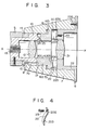
- an endoscope 1 comprises a substantially rectangular box-shaped control section 2, a tubular insertion section 3 projecting from one end of the control section 2, an umbilical cord or connection cord 4 which extends from one lateral wall of the control section 2 and whose free end is fitted with a connector 4a coupled to an external light source (not shown), and a cylindrical ocular section 5 connected to the other end of the control section 2.
- the distal end of the tubular insertion section 3 is provided with an. observation window and an illumination window.
- the observation window is optically connected to the ocular section 5 by means of an image-transmitting optical system extending through the control section 2 and tubular insertion section 3.
- an illumination light supplied from the external light source by means of an illumination optical guide extending through the control section 2, tubular insertion section 3 and umbilical cord 4.
- the other parts of the endoscope of this invention are constructed in the same way as those of the conventional endoscope, description thereof being omitted.
- a photographic camera 6 one of the ocular attachments, is detachably fitted to the ocular section 5 of the endoscope 1 by a bayonet mechanism.
- a hollow cylindrical adapter 7 is formed on the front wall of the photographic camera 6.
- a plurality of bayonet pawls 9 radially project from the inner peripheral wall of the foremost edge portion of the distal end opening 8 equidistantly in the circumferential direction.
- a bayonet ring 10 having an outer diameter substantially equal to the inner diameter of the adapter 7.
- Bayonet grooves 11 engageable with the bayonet pawls 9 are formed in the outer peripheral wall of the bayonet ring 10 equidistantly in the circumferential direction.
- the bayonet grooves 11 receive the corresponding bayonet pawls 9.
- the bayonet pawls 9 act as engagement members, and the bayonet ring 10 is used as a receptacle of the engagement members.
- an ocular 12 is set so as to face the proximal end of an image guide 13 formed of an optical fiber bundle constituting part of the image-transmitting optical system.
- An operation ring 14 is rotatably set on the outer periphery of the ocular section 5 close to the bayonet ring 10.
- Formed in the outer peripheral wall of the operation ring 14 are axially extending notches 15 corresponding to the bayonet grooves 11. Where the notches 15 are aligned with the corresponding grooves 11 by rotating the operation ring 14 in inserting the ocular section 5 into the adapter 7 of the photographic camera 6, the bayonet pawls 9 pass through the bayonet grooves 11 to be engaged with the corresponding notches 15.
- the bayonet ring 10 is securely fitted into the opening 8 of the adapter 7. Later when the adapter 7 is rotated, the operation ring 14 is turned in the same direction, causing the bayonet pawls 9 to be caught by the notches 15 and the inner end of the bayonet ring 10, and enabling the photographic camera 6 to be securely connected to the ocular section 5.
- a smaller diameter cylindrical hole 7a is formed close to the forward end of the adapter 7.
- a larger diameter cylindrical hole 7b is formed close to the rear end of the adapter 7 concentrically with said smaller diameter cylindrical hole 7a.
- the cylindrical holes 7a, 7b are rendered coaxial with the optical axis X-X of the ocular 12.
- a coupling ring 16 comprises a hollow cylindrical body 16a slidably contacting the inner wall of the smaller diameter cylindrical hole 7a and a flange 18 formed concentrically with the hollow cylindrical body 16a at one end thereof and set in a larger diameter cylindrical hole 7b.
- a notch 24 is cut out in the front end portion of a hollow cylindrical body 16a.
- An engagement pin 25 axially projecting from the front end face or distal end face 17 of the bayonet ring 10 in the proximity of the outer periphery of the distal end face 17 of the bayonet ring 10 of the ocular section 5 is carried into the notch 24 when the bayonet ring 10 is inserted into the adapter 7.
- the notch 24 and engagement pin 25 jointly constitute means for preventing the relative rotation of the bayonet ring 10 and coupling ring 16.
- a hollow cylindrical lens mount 22 fixed to the front wall of the photographic camera 6 by set screws 22a.
- a space is provided between the front end face 22b of the lens mount 22 and the front end face 16b of the coupling ring 16, thereby allowing the coupling ring 16 to reciprocate axially of the adapter 7.
- Set in the lens mount 22 is an objective 21 which is rendered coaxial with an optical axis X-X of the ocular 12 when the photographic camera 6 is fitted to the ocular section 5.
- elastically urging means is provided between the front side 22b of the lens mount 22 and the corresponding front end face 16b of the coupling ring 16 normally to urge the coupling ring 16 toward the front end of the adapter 7.
- the rear end face 16c of the coupling ring 16 elastically abuts against the end face 17 of the ocular section 5 by the urging means, and clamps the bayonet ring 10 of the ocular section 5 between the coupling ring 16 and bayonet pawls 9.
- the above-mentioned urging means comprises, for example, a plurality of plate springs 20 shown in Figs. 3 and 4.
- Each plate spring 20 comprises a base portion 20a securely set on the front end face 22b of the lens mount 22 in parallel therewith by a set screw 23 and an arm 20b which extends from the base portion 20a toward the front end face 16b of the coupling ring 16 in an outward convexed form and whose free end portion contacts the front end face 16b in parallel therewith.
- three plate springs 20 are provided (only two are indicated in Fig. 3).
- the rear end face 16c of the coupling ring 16 abuts against the distal end face 17 of the ocular section 5.
- the engagement pin 25 of the ocular section 5 is engaged with the notch 24 of the coupling ring 16. Therefore, the coupling ring 16 and ocular section 5 are assembled as if into a single body, thereby preventing the bayonet ring 10 and coupling ring 16 from being rotated relative to each other even when the adapter 7 is later rotated. In other words, when sliding on the side of the adapter 7, the coupling ring 16 does not rub the distal end face 17 of the ocular section 5. Thus, the distal end face 17 is not mirror polished.
- the coupling ring 16 is pressed by the distal end face 17 of the ocular section 5, and is retracted against the urging force of the plate spring 20, thus remaining in a pressed state in tight contact with the end face 17 of the ocular section 5.
- the bayonet pawls 9 are stopped at the rear end of the bayonet ring 10 and the coupling ring 16 is pressed against the bayonet ring 10 when connection is effected between the ocular section 5 and coupling ring 16, the photographic camera 6 is securely supported by the ocular section 5.
- an endoscope attachment is detachably fitted to the ocular section of the endoscope, it is possible to suppress the appearance of an unnecessary gloss on the end face of the ocular section due to its rubbing.
- an endoscope is applied, for example, in a room where an illumination source is set, the front end face of the ocular section fitted with a photographic camera does not shine at all, thereby eliminating the obstruction of a coeliac observation.
- a photographic camera was used as an attachment to the ocular section of the endoscope.
- this invention is obviously applicable to the case when any other attachment (for example, a teaching scope) is fitted to the ocular section of the endoscope.
Landscapes
- Health & Medical Sciences (AREA)
- Life Sciences & Earth Sciences (AREA)
- Physics & Mathematics (AREA)
- Surgery (AREA)
- Optics & Photonics (AREA)
- Engineering & Computer Science (AREA)
- Heart & Thoracic Surgery (AREA)
- Animal Behavior & Ethology (AREA)
- Radiology & Medical Imaging (AREA)
- Nuclear Medicine, Radiotherapy & Molecular Imaging (AREA)
- Biophysics (AREA)
- Biomedical Technology (AREA)
- Veterinary Medicine (AREA)
- Medical Informatics (AREA)
- Molecular Biology (AREA)
- Pathology (AREA)
- General Health & Medical Sciences (AREA)
- Public Health (AREA)
- General Physics & Mathematics (AREA)
- Mechanical Engineering (AREA)
- Multimedia (AREA)
- Astronomy & Astrophysics (AREA)
- Instruments For Viewing The Inside Of Hollow Bodies (AREA)
- Endoscopes (AREA)
Priority Applications (1)
| Application Number | Priority Date | Filing Date | Title |
|---|---|---|---|
| AT80108034T ATE9615T1 (de) | 1979-12-24 | 1980-12-18 | Vorrichtung zur befestigung eines zusatzgeraetes an einen abschnitt eines endoskopokulars. |
Applications Claiming Priority (2)
| Application Number | Priority Date | Filing Date | Title |
|---|---|---|---|
| JP167775/79 | 1979-12-24 | ||
| JP16777579A JPS5689232A (en) | 1979-12-24 | 1979-12-24 | Endoscope apparatus |
Publications (3)
| Publication Number | Publication Date |
|---|---|
| EP0031151A2 true EP0031151A2 (de) | 1981-07-01 |
| EP0031151A3 EP0031151A3 (en) | 1982-02-10 |
| EP0031151B1 EP0031151B1 (de) | 1984-09-26 |
Family
ID=15855871
Family Applications (1)
| Application Number | Title | Priority Date | Filing Date |
|---|---|---|---|
| EP80108034A Expired EP0031151B1 (de) | 1979-12-24 | 1980-12-18 | Vorrichtung zur Befestigung eines Zusatzgerätes an einen Abschnitt eines Endoskopokulars |
Country Status (5)
| Country | Link |
|---|---|
| US (1) | US4323304A (de) |
| EP (1) | EP0031151B1 (de) |
| JP (1) | JPS5689232A (de) |
| AT (1) | ATE9615T1 (de) |
| DE (1) | DE3069321D1 (de) |
Cited By (6)
| Publication number | Priority date | Publication date | Assignee | Title |
|---|---|---|---|---|
| US4600277A (en) * | 1984-02-13 | 1986-07-15 | Murray Jr Joseph E | Telescope with multiple image-viewing assemblies |
| WO1990013841A1 (en) * | 1989-05-01 | 1990-11-15 | MILLER, Patricia, Hermione (heir of MILLER, David, Dushko (deceased)) | Endoscope support system |
| US5249082A (en) * | 1991-05-08 | 1993-09-28 | Eastman Kodak Company | Exact constraint arrangement for and methods of mounting an element such as a lens |
| US5673143A (en) * | 1995-10-11 | 1997-09-30 | Hughes Electronics | Thermal imaging device with selectively replaceable telescopic lenses and automatic lens identification |
| EP2003482A1 (de) * | 2007-06-11 | 2008-12-17 | Swarovski-Optik KG | Adapter zur Verbindung eines optischen Aufzeichnungsgeräts mit einem Beobachtungsgerät |
| EP2674811A3 (de) * | 2012-06-11 | 2014-01-15 | Swarovski Optik Kg | Objektiv für ein Bildaufzeichnungsgerät |
Families Citing this family (29)
| Publication number | Priority date | Publication date | Assignee | Title |
|---|---|---|---|---|
| US4638792A (en) * | 1979-12-20 | 1987-01-27 | Burgin Kermit H | Adjustable speculum with incorporated lighting system |
| USD270643S (en) | 1981-03-17 | 1983-09-20 | Polaroid Corporation | Photographic camera or similar article |
| JPS5865133A (ja) * | 1981-10-12 | 1983-04-18 | オリンパス光学工業株式会社 | 内視鏡 |
| GB2149932B (en) * | 1983-11-12 | 1986-11-19 | Warner Lambert Tech | Improved endoscope |
| JPH0514258Y2 (de) * | 1985-09-05 | 1993-04-16 | ||
| US4776668A (en) * | 1986-01-09 | 1988-10-11 | Machida, Inc. | Image focusing ocular piece for a viewing scope including mechanism for accommodating differential expansion |
| US4807594A (en) * | 1988-01-15 | 1989-02-28 | Medical Concepts, Incorporated | Adapter assembly for endoscopic video camera |
| US4844071A (en) * | 1988-03-31 | 1989-07-04 | Baxter Travenol Laboratories, Inc. | Endoscope coupler device |
| US5419313A (en) * | 1988-10-27 | 1995-05-30 | Rosemarie Lemke | Microwave sterilizable and reusable endoscope |
| US5205280A (en) * | 1990-12-21 | 1993-04-27 | Mp Video, Inc. | Quick-release endoscopic coupling assembly |
| US5846186A (en) * | 1996-09-24 | 1998-12-08 | Mercury Enterprises, Inc. | Endoscope system and coupling arrangement for use therewith |
| US6106457A (en) * | 1997-04-04 | 2000-08-22 | Welch Allyn, Inc. | Compact imaging instrument system |
| US6840903B2 (en) | 2002-03-21 | 2005-01-11 | Nuvista Technology Corporation | Laryngoscope with image sensor |
| FR2857248B1 (fr) * | 2003-07-07 | 2006-01-27 | Acep France | Dispositif destine a assurer l'examen de la retine d'un patient |
| WO2006122303A2 (en) * | 2005-05-11 | 2006-11-16 | Boston Scientific Limited | Visualization system |
| US20070179342A1 (en) * | 2006-01-12 | 2007-08-02 | Kb Port Llc | Wireless Laryngoscope with Internal Antennae and One Piece Construction Adapted for Laryngoscopy Training |
| US9622651B2 (en) | 2012-01-27 | 2017-04-18 | Kbport Llc | Wireless laryngoscope simulator with onboard event recording adapted for laryngoscopy training |
| DE102012008970B3 (de) * | 2012-05-03 | 2013-06-27 | Joimax Gmbh | Chirurgische Werkzeugeinrichtung |
| JP5980559B2 (ja) * | 2012-05-07 | 2016-08-31 | オリンパス株式会社 | カメラ |
| WO2015020124A1 (ja) * | 2013-08-08 | 2015-02-12 | シャープ株式会社 | 体内監視カメラシステム、体内監視カメラシステムの支持管 |
| JP2015052746A (ja) * | 2013-09-09 | 2015-03-19 | ソニー株式会社 | 立体視内視鏡 |
| CN105555184B (zh) * | 2013-10-31 | 2017-05-24 | 夏普株式会社 | 体内监视摄像机系统 |
| DE102014222880A1 (de) * | 2014-11-10 | 2016-05-12 | Xion Gmbh | Adapter für die Endoskopie |
| JP6464104B2 (ja) * | 2016-01-20 | 2019-02-06 | 富士フイルム株式会社 | 内視鏡用コネクタ、内視鏡および内視鏡システム |
| JP6527646B2 (ja) * | 2017-05-26 | 2019-06-05 | オリンパス株式会社 | 光学ユニット |
| JP7086641B2 (ja) * | 2018-02-28 | 2022-06-20 | ソニー・オリンパスメディカルソリューションズ株式会社 | カメラヘッド及び内視鏡 |
| DE102018130553A1 (de) | 2018-11-30 | 2020-06-04 | Henke-Sass, Wolf Gmbh | Endoskop |
| US11766166B2 (en) * | 2021-06-21 | 2023-09-26 | Karl Storz Se & Co. Kg | Endoscope eyepiece grasping mechanism and endoscope camera head with endoscope eyepiece grasping mechanism |
| DE102021119204A1 (de) | 2021-07-23 | 2023-01-26 | Xion Gmbh | Kamerakopf für Endoskope |
Family Cites Families (15)
| Publication number | Priority date | Publication date | Assignee | Title |
|---|---|---|---|---|
| GB598572A (en) * | 1945-07-07 | 1948-02-20 | Kershaw & Sons Ltd A | Improvements in or relating to securing means for mounting detachable components |
| US2500050A (en) * | 1948-01-07 | 1950-03-07 | Eastman Kodak Co | Camera lens attaching and clamping mechanism |
| DE861754C (de) * | 1948-03-12 | 1953-01-05 | Kern & Co Ag | Fassung fuer photographische Objektive mit einem Blenden- und einem Distanzring |
| US2870674A (en) * | 1956-11-01 | 1959-01-27 | Cecil I Mize | Microscope |
| SU143572A1 (ru) | 1961-04-25 | 1961-11-30 | А.П. Ломовцев | Фотоприставка |
| US3680459A (en) * | 1970-11-06 | 1972-08-01 | Asahi Optical Co Ltd | Camera objective adjustable for flash and non-flash photography |
| GB1423836A (en) * | 1972-07-04 | 1976-02-04 | Makepeace A P W | Coupling together of an instrument for bodily examination and another instrument such as a camera |
| DE2257191A1 (de) * | 1972-11-22 | 1974-05-30 | Weber Josef | Kameraobjektiv |
| JPS5127677A (ja) * | 1974-08-30 | 1976-03-08 | Osaka Denki Co Ltd | Intaarotsukuseigyosochi |
| JPS52144179A (en) * | 1976-05-27 | 1977-12-01 | Fuji Photo Optical Co Ltd | Device for operating endscope camera |
| JPS5922927B2 (ja) * | 1977-02-04 | 1984-05-30 | キヤノン株式会社 | カメラの附属品の装着装置 |
| US4188942A (en) * | 1978-02-27 | 1980-02-19 | American Hospital Supply Corporation | Endoscope and urological instrument lock |
| CH640951A5 (fr) * | 1978-05-22 | 1984-01-31 | Shinano Kikaku Co Ltd | Unite accessoire a fixer sur un objectif. |
| US4157216A (en) * | 1978-06-26 | 1979-06-05 | Polaroid Corporation | Adapter for optically coupling a photographic camera with a viewing device |
| FR2453421A1 (fr) * | 1979-04-06 | 1980-10-31 | Beaulieu Sa | Dispositif de fixation d'objectifs sur camera |
-
1979
- 1979-12-24 JP JP16777579A patent/JPS5689232A/ja active Pending
-
1980
- 1980-12-12 US US06/215,755 patent/US4323304A/en not_active Expired - Lifetime
- 1980-12-18 DE DE8080108034T patent/DE3069321D1/de not_active Expired
- 1980-12-18 AT AT80108034T patent/ATE9615T1/de not_active IP Right Cessation
- 1980-12-18 EP EP80108034A patent/EP0031151B1/de not_active Expired
Cited By (9)
| Publication number | Priority date | Publication date | Assignee | Title |
|---|---|---|---|---|
| US4600277A (en) * | 1984-02-13 | 1986-07-15 | Murray Jr Joseph E | Telescope with multiple image-viewing assemblies |
| WO1990013841A1 (en) * | 1989-05-01 | 1990-11-15 | MILLER, Patricia, Hermione (heir of MILLER, David, Dushko (deceased)) | Endoscope support system |
| US5249082A (en) * | 1991-05-08 | 1993-09-28 | Eastman Kodak Company | Exact constraint arrangement for and methods of mounting an element such as a lens |
| US5673143A (en) * | 1995-10-11 | 1997-09-30 | Hughes Electronics | Thermal imaging device with selectively replaceable telescopic lenses and automatic lens identification |
| EP2003482A1 (de) * | 2007-06-11 | 2008-12-17 | Swarovski-Optik KG | Adapter zur Verbindung eines optischen Aufzeichnungsgeräts mit einem Beobachtungsgerät |
| US7924515B2 (en) | 2007-06-11 | 2011-04-12 | Swarovski-Optik Kg. | Adapter for connecting an optical recording device to an observation device |
| CN101414042B (zh) * | 2007-06-11 | 2014-05-07 | 施华洛世奇光学公司 | 用于连接光学记录装置与观察装置的连接器 |
| EP2674811A3 (de) * | 2012-06-11 | 2014-01-15 | Swarovski Optik Kg | Objektiv für ein Bildaufzeichnungsgerät |
| US9883087B2 (en) | 2012-06-11 | 2018-01-30 | Swarovski-Optik Kg. | Objective for an image recording device |
Also Published As
| Publication number | Publication date |
|---|---|
| ATE9615T1 (de) | 1984-10-15 |
| JPS5689232A (en) | 1981-07-20 |
| DE3069321D1 (en) | 1984-10-31 |
| EP0031151B1 (de) | 1984-09-26 |
| US4323304A (en) | 1982-04-06 |
| EP0031151A3 (en) | 1982-02-10 |
Similar Documents
| Publication | Publication Date | Title |
|---|---|---|
| EP0031151B1 (de) | Vorrichtung zur Befestigung eines Zusatzgerätes an einen Abschnitt eines Endoskopokulars | |
| US4643170A (en) | Endoscope apparatus | |
| JP3739592B2 (ja) | 腹腔鏡装置 | |
| US4727859A (en) | Right angle detachable prism assembly for borescope | |
| US5101807A (en) | Endoscope connecting apparatus | |
| US4534339A (en) | Endoscope | |
| JP5283722B2 (ja) | プッシュ−プッシュ式の挿入/引抜き機構、シャッターモジュラーコネクタおよびシャッターアダプタを有する超小型フォームファクターの単芯光ファイバ相互接続システム、並びにその使用方法 | |
| JP4328711B2 (ja) | 光コネクタプラグ及び光コネクタ | |
| US6540668B1 (en) | Endoscope with a coupling device (video coupler) for connection of a video camera | |
| JP5000778B2 (ja) | 光コネクタプラグ | |
| US5264928A (en) | Universal adapter for mounting cameras to microscopes | |
| US5800343A (en) | Endoscope light guide connector allowing adjustment of the angle of incident light rays | |
| US4569334A (en) | Apparatus for restoring the light transmittance of an image-transmitting optical fiber bundle used in a fiber optic endoscope | |
| US6007255A (en) | Adapter assembly for light source | |
| EP0027651B1 (de) | Endoskopokularteil | |
| JPH0627393A (ja) | 観察装置 | |
| US6522466B2 (en) | Apparatus for observing interior from an ultramicropore space | |
| JPH10178A (ja) | 内視鏡装置における照明光伝送系アダプター | |
| JP4450912B2 (ja) | 内視鏡保持装置 | |
| CA1204973A (en) | Endoscope | |
| JPH05281439A (ja) | 光コネクタ | |
| JPH10300985A (ja) | 多心光コネクタ | |
| EP0392718B1 (de) | Optischer Stecker für Endoskop | |
| JPH0353831B2 (de) | ||
| JPH03224534A (ja) | 内視鏡用コネクタ装置 |
Legal Events
| Date | Code | Title | Description |
|---|---|---|---|
| PUAI | Public reference made under article 153(3) epc to a published international application that has entered the european phase |
Free format text: ORIGINAL CODE: 0009012 |
|
| AK | Designated contracting states |
Designated state(s): AT BE CH DE FR GB IT NL SE |
|
| PUAL | Search report despatched |
Free format text: ORIGINAL CODE: 0009013 |
|
| RHK1 | Main classification (correction) |
Ipc: G02B 7/02 |
|
| AK | Designated contracting states |
Designated state(s): AT BE CH DE FR GB IT NL SE |
|
| 17P | Request for examination filed |
Effective date: 19820204 |
|
| GRAA | (expected) grant |
Free format text: ORIGINAL CODE: 0009210 |
|
| AK | Designated contracting states |
Designated state(s): AT BE CH DE FR GB IT LI NL SE |
|
| PG25 | Lapsed in a contracting state [announced via postgrant information from national office to epo] |
Ref country code: SE Effective date: 19840926 Ref country code: NL Effective date: 19840926 Ref country code: LI Effective date: 19840926 Ref country code: IT Free format text: LAPSE BECAUSE OF FAILURE TO SUBMIT A TRANSLATION OF THE DESCRIPTION OR TO PAY THE FEE WITHIN THE PRESCRIBED TIME-LIMIT;WARNING: LAPSES OF ITALIAN PATENTS WITH EFFECTIVE DATE BEFORE 2007 MAY HAVE OCCURRED AT ANY TIME BEFORE 2007. THE CORRECT EFFECTIVE DATE MAY BE DIFFERENT FROM THE ONE RECORDED. Effective date: 19840926 Ref country code: FR Free format text: THE PATENT HAS BEEN ANNULLED BY A DECISION OF A NATIONAL AUTHORITY Effective date: 19840926 Ref country code: CH Effective date: 19840926 Ref country code: BE Effective date: 19840926 Ref country code: AT Effective date: 19840926 |
|
| REF | Corresponds to: |
Ref document number: 9615 Country of ref document: AT Date of ref document: 19841015 Kind code of ref document: T |
|
| REF | Corresponds to: |
Ref document number: 3069321 Country of ref document: DE Date of ref document: 19841031 |
|
| REG | Reference to a national code |
Ref country code: CH Ref legal event code: PL |
|
| NLV1 | Nl: lapsed or annulled due to failure to fulfill the requirements of art. 29p and 29m of the patents act | ||
| GBPC | Gb: european patent ceased through non-payment of renewal fee | ||
| PLBE | No opposition filed within time limit |
Free format text: ORIGINAL CODE: 0009261 |
|
| STAA | Information on the status of an ep patent application or granted ep patent |
Free format text: STATUS: NO OPPOSITION FILED WITHIN TIME LIMIT |
|
| EN | Fr: translation not filed | ||
| 26N | No opposition filed | ||
| PG25 | Lapsed in a contracting state [announced via postgrant information from national office to epo] |
Ref country code: GB Effective date: 19881118 |
|
| PGFP | Annual fee paid to national office [announced via postgrant information from national office to epo] |
Ref country code: DE Payment date: 19951222 Year of fee payment: 16 |
|
| PG25 | Lapsed in a contracting state [announced via postgrant information from national office to epo] |
Ref country code: DE Effective date: 19970902 |