EP0031880A2 - Verfahren zum Herstellen eines Faserverbundbauteils - Google Patents
Verfahren zum Herstellen eines Faserverbundbauteils Download PDFInfo
- Publication number
- EP0031880A2 EP0031880A2 EP80106661A EP80106661A EP0031880A2 EP 0031880 A2 EP0031880 A2 EP 0031880A2 EP 80106661 A EP80106661 A EP 80106661A EP 80106661 A EP80106661 A EP 80106661A EP 0031880 A2 EP0031880 A2 EP 0031880A2
- Authority
- EP
- European Patent Office
- Prior art keywords
- fiber composite
- glass mold
- separating layer
- reinforcing fibers
- composite component
- Prior art date
- Legal status (The legal status is an assumption and is not a legal conclusion. Google has not performed a legal analysis and makes no representation as to the accuracy of the status listed.)
- Granted
Links
- 238000004519 manufacturing process Methods 0.000 title claims abstract description 7
- 239000000835 fiber Substances 0.000 claims abstract description 52
- 239000002131 composite material Substances 0.000 claims abstract description 41
- 239000011521 glass Substances 0.000 claims abstract description 30
- 238000000034 method Methods 0.000 claims abstract description 20
- 239000012783 reinforcing fiber Substances 0.000 claims description 15
- PCHJSUWPFVWCPO-UHFFFAOYSA-N gold Chemical compound [Au] PCHJSUWPFVWCPO-UHFFFAOYSA-N 0.000 claims description 11
- 239000010931 gold Substances 0.000 claims description 11
- 229910052737 gold Inorganic materials 0.000 claims description 11
- 229920003002 synthetic resin Polymers 0.000 claims description 11
- 239000000057 synthetic resin Substances 0.000 claims description 11
- OKTJSMMVPCPJKN-UHFFFAOYSA-N Carbon Chemical compound [C] OKTJSMMVPCPJKN-UHFFFAOYSA-N 0.000 claims description 5
- 229920000049 Carbon (fiber) Polymers 0.000 claims description 5
- 239000004917 carbon fiber Substances 0.000 claims description 5
- 239000002904 solvent Substances 0.000 claims description 5
- 238000004544 sputter deposition Methods 0.000 claims description 5
- 239000002241 glass-ceramic Substances 0.000 claims description 4
- 229910002804 graphite Inorganic materials 0.000 claims description 3
- 239000010439 graphite Substances 0.000 claims description 3
- 239000000203 mixture Substances 0.000 claims description 3
- 230000003746 surface roughness Effects 0.000 claims description 3
- 229910000510 noble metal Inorganic materials 0.000 claims description 2
- 238000007789 sealing Methods 0.000 claims 1
- 229920005989 resin Polymers 0.000 description 7
- 239000011347 resin Substances 0.000 description 7
- 235000019592 roughness Nutrition 0.000 description 7
- 239000003795 chemical substances by application Substances 0.000 description 4
- 229910052751 metal Inorganic materials 0.000 description 4
- 239000002184 metal Substances 0.000 description 4
- 238000000889 atomisation Methods 0.000 description 3
- 239000003822 epoxy resin Substances 0.000 description 3
- 238000000465 moulding Methods 0.000 description 3
- 229920000647 polyepoxide Polymers 0.000 description 3
- CSCPPACGZOOCGX-UHFFFAOYSA-N Acetone Chemical compound CC(C)=O CSCPPACGZOOCGX-UHFFFAOYSA-N 0.000 description 2
- 239000000470 constituent Substances 0.000 description 2
- 238000010276 construction Methods 0.000 description 2
- 230000007547 defect Effects 0.000 description 2
- 239000012528 membrane Substances 0.000 description 2
- 239000000758 substrate Substances 0.000 description 2
- 239000000956 alloy Substances 0.000 description 1
- 229910045601 alloy Inorganic materials 0.000 description 1
- 238000007664 blowing Methods 0.000 description 1
- 238000004140 cleaning Methods 0.000 description 1
- 239000011248 coating agent Substances 0.000 description 1
- 238000000576 coating method Methods 0.000 description 1
- 238000001816 cooling Methods 0.000 description 1
- 230000000694 effects Effects 0.000 description 1
- 238000001704 evaporation Methods 0.000 description 1
- 230000008020 evaporation Effects 0.000 description 1
- 239000007789 gas Substances 0.000 description 1
- 238000000227 grinding Methods 0.000 description 1
- 238000010438 heat treatment Methods 0.000 description 1
- 239000011261 inert gas Substances 0.000 description 1
- 239000007788 liquid Substances 0.000 description 1
- 239000000463 material Substances 0.000 description 1
- 230000003287 optical effect Effects 0.000 description 1
- 235000011837 pasties Nutrition 0.000 description 1
- 238000005498 polishing Methods 0.000 description 1
- 238000012805 post-processing Methods 0.000 description 1
- 230000005855 radiation Effects 0.000 description 1
- 238000000926 separation method Methods 0.000 description 1
- 229920002545 silicone oil Polymers 0.000 description 1
- 239000001993 wax Substances 0.000 description 1
Images

Classifications
-
- B—PERFORMING OPERATIONS; TRANSPORTING
- B29—WORKING OF PLASTICS; WORKING OF SUBSTANCES IN A PLASTIC STATE IN GENERAL
- B29C—SHAPING OR JOINING OF PLASTICS; SHAPING OF MATERIAL IN A PLASTIC STATE, NOT OTHERWISE PROVIDED FOR; AFTER-TREATMENT OF THE SHAPED PRODUCTS, e.g. REPAIRING
- B29C33/00—Moulds or cores; Details thereof or accessories therefor
- B29C33/42—Moulds or cores; Details thereof or accessories therefor characterised by the shape of the moulding surface, e.g. ribs or grooves
-
- B—PERFORMING OPERATIONS; TRANSPORTING
- B29—WORKING OF PLASTICS; WORKING OF SUBSTANCES IN A PLASTIC STATE IN GENERAL
- B29C—SHAPING OR JOINING OF PLASTICS; SHAPING OF MATERIAL IN A PLASTIC STATE, NOT OTHERWISE PROVIDED FOR; AFTER-TREATMENT OF THE SHAPED PRODUCTS, e.g. REPAIRING
- B29C33/00—Moulds or cores; Details thereof or accessories therefor
- B29C33/56—Coatings, e.g. enameled or galvanised; Releasing, lubricating or separating agents
- B29C33/60—Releasing, lubricating or separating agents
-
- B—PERFORMING OPERATIONS; TRANSPORTING
- B29—WORKING OF PLASTICS; WORKING OF SUBSTANCES IN A PLASTIC STATE IN GENERAL
- B29C—SHAPING OR JOINING OF PLASTICS; SHAPING OF MATERIAL IN A PLASTIC STATE, NOT OTHERWISE PROVIDED FOR; AFTER-TREATMENT OF THE SHAPED PRODUCTS, e.g. REPAIRING
- B29C70/00—Shaping composites, i.e. plastics material comprising reinforcements, fillers or preformed parts, e.g. inserts
- B29C70/04—Shaping composites, i.e. plastics material comprising reinforcements, fillers or preformed parts, e.g. inserts comprising reinforcements only, e.g. self-reinforcing plastics
- B29C70/28—Shaping operations therefor
- B29C70/40—Shaping or impregnating by compression not applied
- B29C70/42—Shaping or impregnating by compression not applied for producing articles of definite length, i.e. discrete articles
- B29C70/44—Shaping or impregnating by compression not applied for producing articles of definite length, i.e. discrete articles using isostatic pressure, e.g. pressure difference-moulding, vacuum bag-moulding, autoclave-moulding or expanding rubber-moulding
-
- B—PERFORMING OPERATIONS; TRANSPORTING
- B29—WORKING OF PLASTICS; WORKING OF SUBSTANCES IN A PLASTIC STATE IN GENERAL
- B29C—SHAPING OR JOINING OF PLASTICS; SHAPING OF MATERIAL IN A PLASTIC STATE, NOT OTHERWISE PROVIDED FOR; AFTER-TREATMENT OF THE SHAPED PRODUCTS, e.g. REPAIRING
- B29C35/00—Heating, cooling or curing, e.g. crosslinking or vulcanising; Apparatus therefor
- B29C35/02—Heating or curing, e.g. crosslinking or vulcanizing during moulding, e.g. in a mould
- B29C35/0227—Heating or curing, e.g. crosslinking or vulcanizing during moulding, e.g. in a mould using pressure vessels, e.g. autoclaves, vulcanising pans
-
- B—PERFORMING OPERATIONS; TRANSPORTING
- B29—WORKING OF PLASTICS; WORKING OF SUBSTANCES IN A PLASTIC STATE IN GENERAL
- B29C—SHAPING OR JOINING OF PLASTICS; SHAPING OF MATERIAL IN A PLASTIC STATE, NOT OTHERWISE PROVIDED FOR; AFTER-TREATMENT OF THE SHAPED PRODUCTS, e.g. REPAIRING
- B29C43/00—Compression moulding, i.e. applying external pressure to flow the moulding material; Apparatus therefor
- B29C43/02—Compression moulding, i.e. applying external pressure to flow the moulding material; Apparatus therefor of articles of definite length, i.e. discrete articles
- B29C43/10—Isostatic pressing, i.e. using non-rigid pressure-exerting members against rigid parts or dies
- B29C43/12—Isostatic pressing, i.e. using non-rigid pressure-exerting members against rigid parts or dies using bags surrounding the moulding material or using membranes contacting the moulding material
-
- B—PERFORMING OPERATIONS; TRANSPORTING
- B29—WORKING OF PLASTICS; WORKING OF SUBSTANCES IN A PLASTIC STATE IN GENERAL
- B29K—INDEXING SCHEME ASSOCIATED WITH SUBCLASSES B29B, B29C OR B29D, RELATING TO MOULDING MATERIALS OR TO MATERIALS FOR MOULDS, REINFORCEMENTS, FILLERS OR PREFORMED PARTS, e.g. INSERTS
- B29K2909/00—Use of inorganic materials not provided for in groups B29K2803/00 - B29K2807/00, as mould material
- B29K2909/08—Glass
-
- B—PERFORMING OPERATIONS; TRANSPORTING
- B29—WORKING OF PLASTICS; WORKING OF SUBSTANCES IN A PLASTIC STATE IN GENERAL
- B29L—INDEXING SCHEME ASSOCIATED WITH SUBCLASS B29C, RELATING TO PARTICULAR ARTICLES
- B29L2009/00—Layered products
-
- B—PERFORMING OPERATIONS; TRANSPORTING
- B32—LAYERED PRODUCTS
- B32B—LAYERED PRODUCTS, i.e. PRODUCTS BUILT-UP OF STRATA OF FLAT OR NON-FLAT, e.g. CELLULAR OR HONEYCOMB, FORM
- B32B38/00—Ancillary operations in connection with laminating processes
- B32B2038/0052—Other operations not otherwise provided for
- B32B2038/0064—Smoothing, polishing, making a glossy surface
-
- Y—GENERAL TAGGING OF NEW TECHNOLOGICAL DEVELOPMENTS; GENERAL TAGGING OF CROSS-SECTIONAL TECHNOLOGIES SPANNING OVER SEVERAL SECTIONS OF THE IPC; TECHNICAL SUBJECTS COVERED BY FORMER USPC CROSS-REFERENCE ART COLLECTIONS [XRACs] AND DIGESTS
- Y10—TECHNICAL SUBJECTS COVERED BY FORMER USPC
- Y10T—TECHNICAL SUBJECTS COVERED BY FORMER US CLASSIFICATION
- Y10T428/00—Stock material or miscellaneous articles
- Y10T428/30—Self-sustaining carbon mass or layer with impregnant or other layer
Definitions
- the invention relates to a method for producing a fiber composite component with a high surface quality.
- the main difficulty is to find a shape of minimal waviness and roughness, from which the fiber composite material can be removed after curing without damaging its surface.
- metal molds are usually used, on their mold surfaces to prevent adhesion between the metal surface and on this hardening fiber composite material liquid or pasty release agents, for. B. dissolved waxes or silicone oils or -pastes, baked and then polished.
- the object of the invention is to provide a method with which fiber composite components of optical surface quality, ie. H. Those for which the maximum approved roughness depth is significantly less than 1 ⁇ m and can even be below 0.2 ⁇ m can be produced without any problems.
- this object is achieved by the method characterized in claim 1.
- the use of a glass mold, the surface quality of which far exceeds that of a metal mold (roughness depths of less than 0.01 ⁇ m can be achieved), and the special, uniformly thin, continuous coating of the glass mold surface with a release agent free of volatile constituents, according to the invention Obtain fiber composite component which can be easily separated from the molded part after curing and which has a surface which is highly precise in terms of ripple and roughness in the region of visible radiation and which reflects almost without distortion.
- the fiber composite component produced according to the invention is particularly suitable for applications, for example in satellite construction, where in addition to an extremely low construction weight, high rigidity and low thermal expansion coefficient, an optically high-quality, mirror-smooth surface finish is required.
- the separating layer can be evaporated, but is preferably applied by sputtering onto the glass mold surface (sputtering), as a result of which an extremely uniform layer thickness can be achieved and post-processing of the separating layer, which would impair the surface accuracy of the fiber composite component, is omitted .
- sputtering sputtering
- it is expediently not or not substantially thicker than the maximum permitted roughness depth of the fiber composite component and has a preferred layer thickness of approximately 200-400 ⁇ .
- any material that can be vapor-deposited or sputtered onto glass can be used as a release agent, which does not adhere more strongly to the glass mold than to the fiber composite material, but expediently, however, the separating layer according to claim 2 consists of gold or a similar noble metal, which is then removed from the mold after demolding. collar component is removed according to claim 5 by a suitable solvent.
- the fiber arrangement according to claim 8 is expediently chosen.
- a very thin, pure synthetic resin layer is preferably first applied to the separating layer, and only after this synthetic resin layer has hardened are the reinforcing fibers applied, graphite also being admixed with the synthetic resin for reasons of low shrinkage.
- the hardening of the fiber composite material on the glass mold is expediently carried out in an autoclave according to claims 14 and 15, with evacuation of the mold space in order to remove possible air pockets, the autoclave pressure being kept substantially lower than usual so that the reinforcing fibers do not press through into the separating layer and Mark on the surface of the fiber composite component.
- the glass mold After the demolding of the fiber composite component together with the separating layer, the glass mold can be used again, but is expediently freed of any residues beforehand according to claim 16.
- a glass mold is produced in the form of a glass ceramic plate 2, which is brought to a surface roughness of approximately 0.008 ⁇ m by grinding and polishing. Then the polished glass mold surface is continuously coated with a closed, uniformly thin separating layer 4 made of gold, namely the gold layer 4 is either vapor-deposited or - as preferred - applied by sputtering in the atomization chamber 6 shown schematically in FIG.
- a gas tank 16 is introduced into the chamber 6 via a micrometer valve 18 and an electrical voltage is applied between the substrate holder 8 and the gold target 12 until the glass mold surface is sputtered with a gold separating layer 4 in the desired thickness - approximately 200-400 A.
- the glass mold 2 is then placed with the gold separating layer 4 upwards on a heating plate and heated to approximately 100-120 ° C.
- An intermediate layer 20 of fiber-free synthetic resin is now applied in an amount of approximately 0.1 g resin per cm 2 of separating layer area.
- the intermediate layer 20 consists of an epoxy resin mixture which contains about 20% intensely mixed graphite powder in order to keep the shrinkage coefficient small.
- the graphite resin system is distributed from the center to the edges of the gold separating layer 4, and any air bubbles which may be formed are removed by blowing the intermediate layer 20 with hot air.
- the carbon fibers pre-impregnated with resin are placed in the form of a fiber composite material layer 22 consisting of unidirectional fiber bundles, depending on the desired layer structure and layer thickness, and covered with a multi-layer tear-off film 24.
- This arrangement is then closed in a pressure-tight manner by a flexible membrane 26 and cured in an autoclave 28 (FIG. 2) at approximately 150 ° C. and with evacuation of the interior delimited by the membrane 26.
- an autoclave pressure p of about 0.5-1.0 bar is used. Vakeum and pressure should also be maintained during the cooling phase.
- the fiber composite component including the gold separating layer 4 is pressed off from the glass molding plate 2, and the gold layer 4 can be effortlessly removed by a solvent, e.g. B. acetone, remove.
- the finished fiber composite component then has almost the same surface quality as the glass molding plate 2. This can be reused after cleaning with a solvent, for example 1-methylpyrolidone- (2).
- thermal expansion coefficients of the same size are chosen for the glass molding plate 2, the reinforcing fibers and the synthetic resin.
- This interference caused by different thermal expansion can, if desired, be selected by choosing a suitable type or mixture of fibers, the thermal expansion coefficient of which is closer to that of the epoxy resin component, or possibly also by keeping the operating temperature of the fiber composite component at or near the curing temperature .
- resin shrinkage Another disruptive factor affecting the surface quality of the fiber composite component is resin shrinkage, which is approximately 3%.
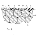
- the intermediate layer 20 is applied somewhat thicker, and the reinforcing fibers 30 are only placed on the intermediate layer 20 after it has hardened, so that the component surface designated by B in FIG. 3 is formed.
- the fiber composite component surfaces obtained with the described method are optically reflective and have surface roughnesses of less than 0.2 ⁇ m.
Landscapes
- Engineering & Computer Science (AREA)
- Mechanical Engineering (AREA)
- Chemical & Material Sciences (AREA)
- Composite Materials (AREA)
- Moulds For Moulding Plastics Or The Like (AREA)
- Moulding By Coating Moulds (AREA)
- Laminated Bodies (AREA)
- Casting Or Compression Moulding Of Plastics Or The Like (AREA)
Abstract
Description
- Die Erfindung bezieht sich auf ein Verfahren zum Herstellen eines Faserverbundbauteils hoher Oberflächengüte.
- Bei der Herstellung von Faserverbundbauteilen mit hochglatter, z. B. optisch spiegelnder Oberfläche besteht die Hauptschwierigkeit darin, eine Formfläche minimaler Welligkeit und Rauhtigkeit zu finden, von der sich der Faserverbundwerkstoff nach dem Aushärten ohne Beschädigung seiner Oberfläche ablösen läßt. Zu diesem Zweck werden üblicherweise Metallformen verwendet, auf deren Formflächen zur Verhinderung einer Adhäsion zwischen Metallfläche und auf dieser aushärtendem Faserverbundwerkstoff flüssige oder pastöse Trennmittel, z. B. gelöste Wachse oder Silikonöle oder -pasten, eingebrannt und dann poliert werden. Bedingt durch die kristalline Struktur solcher Metallformen, sowie aufgrund von Legierungserscheinungen und Feinstrißbildungen an der Oberfläche, und weil zudem nach dem Verdampfen der flüchtigen Bestandteile des Trennmittels eine Trennschicht ungleichförmiger Schichtdicke zurückbleibt, liegt aber die auf diese Weise an solchen Formflächen erzielbare Rauhtiefe und Welligkeit weit über denjenigen Grenzwerten, die für die Herstellung von Faserverbundbauteilen mit optisch hochwertiger Oberflächenqualität erforderlich sind.
- Aufgabe der Erfindung ist es, ein Verfahren anzugeben, mit dem sich Faserverbundbauteile optischer Oberflächengüte, d. h. solche, für die die maximal zugelassene Rauhtiefe wesentlich kleiner als 1 µm ist und sogar unter 0, 2 µm liegen kann, problemlos herstellen lassen.
- Diese Aufgabe wird erfindungsgemäß durch das imAnspruch 1 gekennzeichnete Verfahren gelöst.
- Durch die Verwendung einer Glasform, deren Oberflächengüte die einer Metallform bei weitem übertrifft (es sind Rauhtiefen von unter 0, 01 µm erzielbar), sowie die besondere, gleichmäßig dünne, durchgehende Beschichtung der Glasform-Oberfläche mit einem von flüchtigen Bestandteilen freien Trennmittel wird erfindungsgemäß ein Faserverbundbauteil erhalten, das sich nach dem Aushärten leicht von dem Formteil trennen läßt und eine hinsichtlich Welligkeit und Rauigkeit hochpräzise im Bereich der sichtbaren Strahlung nahezu verzerrungsfrei spiegelnde Oberfläche aufweist. Das erfindungsgemäß hergestellte Faserverbundbauteil ist insbesondere für Anwendungsfälle, etwa im Satellitenbau, geeignet, wo neben einem extrem niedrigen Baugewicht, hoher Steifigkeit und geringem thermischen Ausdehnungskoeffizienten eine optisch hochwertige, spiegelglatte Oberflächenbeschaffenheit gefordert wird.
- Die Trennschicht kann aufgedampft werden, wird aber vorzugsweise gemäß Anspruch 2 im Wege: der Kathodenzerstäubung auf die Glasform-Oberfläche aufgebracht (aufgesputtert), wodurch sich eine äußerst gleichförmige Schichtdicke erzielen läßt und eine Nachbearbeitung der Trennschicht, die die Oberflächengenauigkeit des Faserverbundbauteils beeinträchtigen würde, entfällt. Ebenfalls um durch das Auftragen der Trennschicht bedingte Oberflächenfehler zu vermeiden, ist diese gemäß Anspruch 4 zweckmäßigerweise nicht oder nicht wesentlich dicker als die maximal zugelassene Rauhtiefe des Faserverbundbauteils und hat eine bevorzugte Schichtdicke von etwa 200 - 400 Ä.
- Im Prinzip läßt sich als Trennmittel jedes auf Glas aufdampfbare oder aufsputterbare Material verwenden, das an der Glasform nicht stärker als an dem Faserverbundwerkstoff haftet, zweckmäßigerweise aber besteht die Trennschicht gemäß Anspruch 2 aus Gold oder einem ähnlichen Edelmetall, das dann nach dem Entformen des Faserver.bundbauteils gemäß Anspruch 5 durch ein geeignetes Lösungsmittel entfernt wird.
- Um die, wenn auch im allgemeinen geringen,Oberflächenfehler, die sich beim Aushärten und bei der Anwendung des Faserverbundbauteils unter der Wirkung von Temperaturänderungen ergeben, weitgehend auszuschalten, empfiehlt es sich gemäß den Ansprüchen 6, 7 und 13, die thermischen Ausdehnungskoeffizienten von Glasform und Verstärkungsfasern einerseits und von Kunstharz und Verstärkungsfasern andererseits zumindest annähernd gleichzuhalten. Aus dem gleichen Grund, und um zudem ein örtliches Durchdrücken einzelner Verstärkungsfasern beim Aushärten unter Druckeinwirkung zu verhindern, wird zweckmäßigerveise die Faseranordnung gemäß Anspruch 8 gewählt. Um den durch die Schrumpfung der Kunstharzkomponente des Faserverbundwerkstoffs beim Aushärten bedingten Störeinfluß kleinzuhalten und sicherzustellen, daß sich die oberste Faserlage nicht auf der Oberfläche des Faserverbundbauteils abzeichnet, wird gemäß den Ansprüchen 9 - 12 vorzugsweise zunächst eine sehr dünne, reine Kunstharzschicht auf die Trennschicht aufgetragen, und erst nach dem Anhärten dieser Kunstharzschicht werden die Verstärkungsfasern aufgelegt, wobei dem Kunstharz ebenfalls aus Gründen einer geringen Schrumpfung Graphit beigemischt ist.
- Das Aushärten des Faserverbundwerkstoffs auf der Glasform wird zweckmäßigerweise gemäß den Ansprüchen 14 und 15 imAutoklaven durchgeführt, und zwar unter Evakuierungdes Formraums, um mögliche Lufteinschlüsse zu entfernen, wobei der Autoklavendruck wesentlich niedriger als üblich gehalten wird, damit sich die Verstärkungsfasern nicht in die Trennschicht durchdrücken und auf der Oberfläche des Faserverbundbauteils abzeichnen.
- Nach dem Entformen des Faserverbundbauteils zusammen mit der Trennschicht ist die Glasform erneut verwendbar, wird aber zuvor zweckmäßigerweise gemäß Anspruch 16 von eventuellen Rückständen befreit.
- Die Erfindung wird nunmehr anhand eines Ausführungsbeispiels in Verbindung mit den Zeichnungen näher erläutert. Es zeigt:
- Fig. 1 eine schematische Darstellung einer Zerstäubungskammer zum Aufsputtern der Trennschicht auf die Glasform;
- Fig. 2 die aus Glasform und Faserverbundwerkstoff bestehende Anordnung beim Aushärten im Autoklaven;
- Fig. 3 eine stark vergrößerte Teildarstellung der Oberflächenstruktur des fertigen Faserverbundbauteils.
- Das Verfahren wird anhand der Herstellung eines ebenen Faserverbundbauteils aus mit Kunstharz vorimprägnierten Carbonfasern mit einem Faserdurchmesser d = 8 pm beschrieben.
- Zunächst wird eine Glasform in Form einer Glaskeramikplatte 2 hergestellt, die durch Schleifen und Polieren auf eine Oberflächenrautiefe von etwa 0, 008 µm gebracht wird. Dann wird die polierte Glasformfläche durchgehend mit einer geschlossenen, gleichmäßig dünnen Trennschicht 4 aus Gold überzogen, und zwar wird die Goldschicht 4 entweder aufgedampft oder - wie bevorzugt - durch Kathodenzerstäubung in der in Figur 1 schematisch gezeigten Zerstäubungskammer 6 aufgebracht (aufgesputtert). Diese enthält einen als Anode wirkenden Substrathalter 8, auf den die Glaskeramikplatte 2 mit der polierten Glasfläche nach oben aufgelegt wird, und ein als Kathode wirkendes, zwischen Abschirmelementen 10 angeordnetes Goldtarget 12. Nach dem Evakuieren der Zerstäubungskammer 6 über eine Vakeumpumpe 14 wird ein Inertgas aus einem Gastank 16 über ein Mikrometerventil 18 in die Kammer 6 eingebracht und eine elektrische Spannung zwischen Substrathalter 8 und Goldtarget 12 angelegt, bis die Glasformfläche mit einer Gold-Trennschicht 4 in der gewünschten Dicke - etwa 200 - 400 A - besputtert ist.
- Die Glasform 2 wird dann mit der Gold-Trennschicht 4 nach oben auf eine Heizplatte gelegt und auf ca. 100 - 120 °C erwärmt. Nunmehr wird eine Zwischenschicht 20 aus faserfreiem Kunstharz in einer Menge von etwa 0, 1 g Harz pro cm2 Trennschichtfläche aufgetragen. Die Zwischenschicht 20 besteht aus einem Epoxidharzgemisch, das etwa 20 % intensiv vermischtes Graphitpulver enthält, um den Schrumpfungskoeffizienten kleinzuhalten. Das Graphit-Harzsystem wird von der Mitte zu den Rändern der Gold-Trennschicht 4 verteilt,und evtl. entstehende Luftblasen werden durch Anblasen der Zwischenschicht 20 mit Heißluft entfernt. Nach dem Anhärten der Zwischenschicht 20 (nach etwa 1 - 2 h) werden die mit Harz vorimprägnierten Carbonfasern in Form einer aus unidirektionalen Faserbündeln bestehenden Faserverbundwerkstoffschicht 22 je nach gewünschten Lagenaufbau und Schichtdicke aufgelegt und mit einer mehrlagigen Abreißfolie 24 abgedeckt.
- Diese Anordnung wird dann durch eine flexible Membran 26 druckdicht verschlossen und in einem Autoklaven 28 (Figur 2) bei etwa 150 0c und unter Evakuierung des von der Membran 26 begrenzten Innenraums ausgehärtet. Um ein Durchdrücken der Faserstruktur zu verhindern, wird mit einem reduzierten Autoklavendruck p von etwa 0, 5 - 1, 0 bar gearbeitet. Vakeum und Druck sind auch während der Abkühlphase beizubehalten.
- Nach dem Aushärten wird das Faserverbundbauteil einschließlich der Gold-Trennschicht 4 von der Glasformplatte 2 abgedrückt, und die Goldschicht 4 läßt sich bei Bedarf mühelos durch ein Lösungsmittel, z. B. Aceton, entfernen. Das fertige Faserverbundbauteil hat dann nahezu die gleiche Oberflächenqualität wie die Glasformplatte 2. Diese ist nach Reinigung mit einem Lösungsmittel, etwa 1-Methylpyrolidon- (2) wiederverwendbar.
- Um die durch Temperaturänderungen beim Aushärten und im Gebrauch des Faserverbundbauteils bedingten Oberflächenungenauigkeiten kleinzuhalten, werden für die Glasformplatte 2, die Verstärkungsfasern und das Kunstharz möglichst gleich große thermische Ausdehnungskoeffizienten gewählt. Glaskeramik und Carbonfasern haben annähernd den gleichen Wärmeausdehnungskoeffizienten, hingegen liegt der Ausdehnungskoeffizient üblicher Epox i d harzsysteme etwa 3 mal so hoch wie der von Carbonfasern, was bei einem Temperaturgradienten von 150 °C und einem Faserdurchmesser d = 8 µm eine Oberflächenra4tiefe von etwa 0, 013 um ergibt. Dieser, durch unterschiedliche Wärmeausdehnung bedingte Störeinfluß läßt sich gewünschtenfalls durch Wahl einer geeigneten Fasersorte oder -mischung, deren thermischer Ausdehnungskoeffizient näher an dem der Epox i d harzkomponente liegt, oder evtl. auch dadurch verringern, daß die Betriebstemperatur des Faserverbundbauteils auf oder nahe der Aushärttemperatur gehalten wird.
- Ein weiterer, die Oberflächengüte des Faserverbundbauteils beeinträchtigender Störfaktor ist der Harzschrumpf, der etwa 3 % beträgt. Zur Verringerung dieses Störfaktors ist dem Harzsystem der Zwischenschicht 20 Graphitpulver zugemischt, und wenn diese Zwischenschicht 20 nur die Zwischenräume zwischen den Verstärkungsfasern 30 der obersten Faserlage 32 (Figur 3) ausfüllt, ergibt sich unter Berücksichtigung des Harzschrumpfes ein zwischen den Einzelfasern 30 konkav gewölbtes Oberflächenprofil A mit einer Rauhtiefe t = 0, 12 pm. Um den Einfluß des Harzschrumpfes weiter zu verringern, wird die Zwischenschicht 20 etwas dicker aufgetragen, und die Verstärkungsfasern 30 werden erst nach dem Anhärten der Zwischenschicht 20 auf diese aufgelegt, so daß die in Figur 3 mit B bezeichnete Bauteil-Oberfläche entsteht.
- Die mit dem beschriebenen Verfahren erhaltenen Faserverbundbauteil-Oberflächen sind optisch spiegelnd und haben Raütiefen von weniger als 0,2 µm.
Claims (16)
Applications Claiming Priority (2)
| Application Number | Priority Date | Filing Date | Title |
|---|---|---|---|
| DE3000216 | 1980-01-04 | ||
| DE19803000216 DE3000216A1 (de) | 1980-01-04 | 1980-01-04 | Verfahren zum herstellen eines faserverbundbauteils |
Publications (3)
| Publication Number | Publication Date |
|---|---|
| EP0031880A2 true EP0031880A2 (de) | 1981-07-15 |
| EP0031880A3 EP0031880A3 (en) | 1983-03-09 |
| EP0031880B1 EP0031880B1 (de) | 1985-07-10 |
Family
ID=6091549
Family Applications (1)
| Application Number | Title | Priority Date | Filing Date |
|---|---|---|---|
| EP80106661A Expired EP0031880B1 (de) | 1980-01-04 | 1980-10-30 | Verfahren zum Herstellen eines Faserverbundbauteils |
Country Status (4)
| Country | Link |
|---|---|
| US (1) | US4353964A (de) |
| EP (1) | EP0031880B1 (de) |
| JP (1) | JPS56101830A (de) |
| DE (1) | DE3000216A1 (de) |
Cited By (2)
| Publication number | Priority date | Publication date | Assignee | Title |
|---|---|---|---|---|
| FR2707427A1 (fr) * | 1993-07-07 | 1995-01-13 | Deutsche Forsch Luft Raumfahrt | Procédé de réalisation d'un moule négatif pour réflecteurs d'antennes paraboliques réflecteur obtenu et dispositif de presse pour réaliser des corps composites pour ces réflecteurs. |
| EP0716118A3 (de) * | 1994-08-05 | 1997-04-09 | Sasib Spa | Gefüllte Epoxidharzmischung und Verfahren zum Giessen von statischen Maschinenteilen daraus |
Families Citing this family (21)
| Publication number | Priority date | Publication date | Assignee | Title |
|---|---|---|---|---|
| US4489027A (en) * | 1982-08-11 | 1984-12-18 | The United States Of America As Represented By The Administrator Of The National Aeronautics And Space Administration | Process for preparing solvent resistant, thermoplastic aromatic poly(imidesulfone) |
| JPS61263716A (ja) * | 1985-05-09 | 1986-11-21 | Mitsubishi Electric Corp | 繊維強化プラスチツク製反射鏡の製造方法 |
| JPS61255838A (ja) * | 1985-05-09 | 1986-11-13 | Mitsubishi Electric Corp | 繊維強化プラスチツク製反射鏡の製造方法 |
| US5484498A (en) * | 1987-05-07 | 1996-01-16 | Hogarth; Harold P. | Molded article and method and apparatus for making same |
| US5122226A (en) * | 1987-08-12 | 1992-06-16 | United Technologies Corporation | Method of making hybrid composite structures of fiber reinforced glass and resin matrices |
| US5071506A (en) * | 1987-10-09 | 1991-12-10 | Thiokol Corporation | Equipment for making composite tubes including an inflatable heated bladder and a composite mold having a negative coefficient of thermal expansion |
| FR2655364B1 (fr) * | 1989-12-01 | 1992-04-10 | Europ Propulsion | Procede de fabrication d'une piece en materiau composite, notamment a texture fibres de carbone ou refractaires et matrice carbone ou ceramique. |
| US5217729A (en) * | 1990-03-22 | 1993-06-08 | Toppan Printing Co., Ltd. | Mold for plastic bottles |
| FR2659949B1 (fr) * | 1990-03-26 | 1992-12-04 | Europ Propulsion | Procede de conformation d'une texture fibreuse de renfort pour la fabrication d'une piece en materiau composite. |
| FR2670427B1 (fr) * | 1990-12-18 | 1994-07-08 | Francois Savigny | Procede de moulage sous vide d'un panneau en materiau plastique et panneau obtenu selon le procede. |
| US5320700A (en) * | 1991-04-15 | 1994-06-14 | Phillips Petroleum Company | Process for molding utilizing compression sleeve |
| US5322653A (en) * | 1992-06-05 | 1994-06-21 | Mueller Hans | Method of repairing buried sewage pipes |
| US5433165A (en) * | 1994-03-30 | 1995-07-18 | Outboard Marine Corporation | Method of manufacturing a boat hull |
| US5588392A (en) * | 1995-04-18 | 1996-12-31 | Outboard Marine Corporation | Resin transfer molding process |
| US6017484A (en) * | 1997-01-21 | 2000-01-25 | Harold P. Hale | Method for manufacture of minimum porosity, wrinkle free composite parts |
| US6367406B1 (en) * | 1999-09-24 | 2002-04-09 | Larson/Glastron Boats, Inc. | Boat and method for manufacturing using resin transfer molding |
| JP5044220B2 (ja) * | 2004-01-20 | 2012-10-10 | タッチストーン リサーチ ラボラトリー, リミテッド | 炭素発泡体複合ツールおよび炭素発泡体複合ツールを使用するための方法 |
| US20060057335A1 (en) * | 2004-09-14 | 2006-03-16 | Chen-Shih Wang | Molded fiber panel having reduced surface fiber readout and method of molding thereof |
| NL1029471C2 (nl) * | 2005-07-08 | 2007-01-09 | Crehabo Belgium N V | Werkwijze en inrichting voor het vervaardigen van een vormdeel uit een kunststof. |
| WO2008089334A2 (en) | 2007-01-19 | 2008-07-24 | Vec Industries, L.L.C. | Method and apparatus for molding composite articles |
| FR2962680B1 (fr) * | 2010-07-15 | 2012-08-10 | Airbus Operations Sas | Procede de fabrication de pieces en materiau composite et pieces ainsi obtenues |
Family Cites Families (10)
| Publication number | Priority date | Publication date | Assignee | Title |
|---|---|---|---|---|
| US2464157A (en) * | 1944-06-28 | 1949-03-08 | Rca Corp | Mold |
| GB643022A (en) * | 1947-04-08 | 1950-09-15 | Archibald & Company Ltd J | An improved metal-coated sheet material for sequins and a process for making the same |
| US2992956A (en) * | 1958-02-14 | 1961-07-18 | American Optical Corp | Method for making fiber optical devices |
| GB1081911A (en) * | 1964-02-19 | 1967-09-06 | English Electric Co Ltd | Improvements in or relating to reinforced plastics |
| US3629388A (en) * | 1970-01-12 | 1971-12-21 | Rosanne A Levitsky | Casting procedure for high quality epoxy layers |
| US3681483A (en) * | 1970-07-13 | 1972-08-01 | Richard E Moore | Pressure polishing of extruded polycarbonate or polysulfone sheet |
| JPS518990B1 (de) * | 1971-02-01 | 1976-03-23 | ||
| JPS5149259A (ja) * | 1974-10-11 | 1976-04-28 | Teijin Chemicals Ltd | Goseijushichukeiseikeihinno seizoho |
| US4017238A (en) * | 1975-04-21 | 1977-04-12 | American Optical Corporation | Mold for casting contact lenses utilizing and electron beam to polymerize the resin lens |
| CA1110026A (en) * | 1977-11-09 | 1981-10-06 | Benzion Landa | Squeegee roller and method of making same |
-
1980
- 1980-01-04 DE DE19803000216 patent/DE3000216A1/de not_active Ceased
- 1980-10-30 EP EP80106661A patent/EP0031880B1/de not_active Expired
- 1980-12-18 JP JP17965480A patent/JPS56101830A/ja active Pending
-
1981
- 1981-01-12 US US06/223,940 patent/US4353964A/en not_active Expired - Fee Related
Cited By (2)
| Publication number | Priority date | Publication date | Assignee | Title |
|---|---|---|---|---|
| FR2707427A1 (fr) * | 1993-07-07 | 1995-01-13 | Deutsche Forsch Luft Raumfahrt | Procédé de réalisation d'un moule négatif pour réflecteurs d'antennes paraboliques réflecteur obtenu et dispositif de presse pour réaliser des corps composites pour ces réflecteurs. |
| EP0716118A3 (de) * | 1994-08-05 | 1997-04-09 | Sasib Spa | Gefüllte Epoxidharzmischung und Verfahren zum Giessen von statischen Maschinenteilen daraus |
Also Published As
| Publication number | Publication date |
|---|---|
| JPS56101830A (en) | 1981-08-14 |
| DE3000216A1 (de) | 1981-07-09 |
| EP0031880A3 (en) | 1983-03-09 |
| EP0031880B1 (de) | 1985-07-10 |
| US4353964A (en) | 1982-10-12 |
Similar Documents
| Publication | Publication Date | Title |
|---|---|---|
| EP0031880A2 (de) | Verfahren zum Herstellen eines Faserverbundbauteils | |
| DE1758845C3 (de) | Verfahren zur Herstellung von Prazisions gießformen fur reaktionsfähige Metalle | |
| DE69311840T2 (de) | Pressform zur Herstellung eines mikro-optischen Elementes, zugehöriges Herstellungsverfahren, mikro-optisches Element und Herstellungsverfahren | |
| DE69723173T2 (de) | Herstellungsverfahren für einen keramischen Kern einer Zahnprothese | |
| EP0034329B1 (de) | Panzerung | |
| DE2937417A1 (de) | Schaum-enthaltende strukturen | |
| DE10340863A1 (de) | Verfahren zur Herstellung einer Dünnschicht aus Al-SiC-Verbundmaterial | |
| EP1600798B1 (de) | Ultraleichter und ultrasteifer vollkeramischer Reflektor | |
| DE2743911B2 (de) | ||
| DE2751221A1 (de) | Verfahren zur aufbringung eines reflexionsvermindernden belages auf unterlagen aus organischem material | |
| EP0658967B1 (de) | Magnetkreiselpumpe für aggressive medien | |
| DE3612325C2 (de) | ||
| DE2315797A1 (de) | Verfahren zur herstellung von keramiksubstraten fuer duennschichtschaltungen | |
| EP1752227B1 (de) | Antihaftbeschichtung, Verfahren zu deren Herstellung und antihaftbeschichtete Substratmaterialien | |
| DE69606520T2 (de) | Verfahren zur herstellung einer walze, walze, und beschichtung für eine walze, zur anwendung in der papierherstellung | |
| DE2432536A1 (de) | Verfahren zur herstellung einer schleifund polierscheibe | |
| DE2355091A1 (de) | Verfahren zur herstellung optischer elemente | |
| EP0001286B1 (de) | Verfahren zum Imprägnieren von Armierungsfasern, Armierungsgeweben, Vliesen od.dgl. | |
| DE69223378T2 (de) | Verfahren zur Herstellung von faserverstärkten Verbundwerkstoffen mit Metallmatrix und Vorformen dafür | |
| DE69512438T2 (de) | Vorform zur herstellung eines faserverstärkten kompositmaterials | |
| DE2634794A1 (de) | Verschleissfestes bauteil fuer papiermaschinen und verfahren zum herstellen solcher bauteile | |
| EP0483199A1 (de) | Verfahren zur herstellung oxidkeramischer formkörper durch thermisches spritzen. | |
| DE69703750T2 (de) | Verfahren zur herstellung einer sinternplatte/substrat und seiner anwendung zum heissen von keramischen artikeln | |
| DE3810851C2 (de) | Verfahren zur Herstellung von Formteilen | |
| DE3842984C1 (de) |
Legal Events
| Date | Code | Title | Description |
|---|---|---|---|
| PUAI | Public reference made under article 153(3) epc to a published international application that has entered the european phase |
Free format text: ORIGINAL CODE: 0009012 |
|
| AK | Designated contracting states |
Designated state(s): FR GB IT |
|
| PUAL | Search report despatched |
Free format text: ORIGINAL CODE: 0009013 |
|
| AK | Designated contracting states |
Designated state(s): FR GB IT |
|
| 17P | Request for examination filed |
Effective date: 19830316 |
|
| ITF | It: translation for a ep patent filed | ||
| GRAA | (expected) grant |
Free format text: ORIGINAL CODE: 0009210 |
|
| AK | Designated contracting states |
Designated state(s): FR GB IT |
|
| ET | Fr: translation filed | ||
| PLBI | Opposition filed |
Free format text: ORIGINAL CODE: 0009260 |
|
| 26 | Opposition filed |
Opponent name: M A N TECHNOLOGIE GMBH Effective date: 19860408 |
|
| RDAG | Patent revoked |
Free format text: ORIGINAL CODE: 0009271 |
|
| STAA | Information on the status of an ep patent application or granted ep patent |
Free format text: STATUS: PATENT REVOKED |
|
| GBPR | Gb: patent revoked under art. 102 of the ep convention designating the uk as contracting state | ||
| 27W | Patent revoked |
Effective date: 19880728 |