EP0031935A2 - Dispositif pour l'alimentation et la commande de plusieurs véhicules miniatures entrainés électriquement - Google Patents
Dispositif pour l'alimentation et la commande de plusieurs véhicules miniatures entrainés électriquement Download PDFInfo
- Publication number
- EP0031935A2 EP0031935A2 EP80108015A EP80108015A EP0031935A2 EP 0031935 A2 EP0031935 A2 EP 0031935A2 EP 80108015 A EP80108015 A EP 80108015A EP 80108015 A EP80108015 A EP 80108015A EP 0031935 A2 EP0031935 A2 EP 0031935A2
- Authority
- EP
- European Patent Office
- Prior art keywords
- pulse
- receiver
- information
- pulses
- vehicles
- Prior art date
- Legal status (The legal status is an assumption and is not a legal conclusion. Google has not performed a legal analysis and makes no representation as to the accuracy of the status listed.)
- Granted
Links
Images



Classifications
-
- A—HUMAN NECESSITIES
- A63—SPORTS; GAMES; AMUSEMENTS
- A63H—TOYS, e.g. TOPS, DOLLS, HOOPS OR BUILDING BLOCKS
- A63H19/00—Model railways
- A63H19/24—Electric toy railways; Systems therefor
Definitions
- the invention relates to a method for the simultaneous selective transmission of digital information and electrical power to several electric model vehicles (e.g. model trains or cars on model racetracks), in which several vehicles are operated and controlled together with conventional DC voltage or network frequency controlled vehicles.
- This task is in toy technology.
- model railroad for example, simultaneous independent driving of several trains is desirable.
- Previous solutions only achieve this goal with restrictions.
- the driving behavior of the model trains is regulated via a low voltage, which is fed to the drive motors by means of a conductor (rails and / or overhead line). If several trains in the model system are to run independently of one another, they must be on different, isolated circuits.
- a frequently used principle for controlling an additional train on one and the same circuit uses an AC voltage superimposed on the conventional DC circuit. This delivers the energy required by the second train and simultaneously controls the speed of the second train by varying the amplitude and phase position.
- mains frequency 50 Hz or 60 Hz
- undesirable performance degradation and additional mechanical and thermal loads on the traction motors occur.
- Another disadvantage is the restriction to only two trains on one circuit.
- Each model with a traction motor contains an electrical receiver and control circuit, which is addressed selectively by a control panel and doses the driving energy for the traction motor from the applied AC voltage in a suitable manner and converts it into direct current by means of a rectifier circuit, which is suitable for DC model railroad motors.
- a conventional, adjustable, reversible polarity direct current source 2 is connected in series with a choke 3 to a current-conducting pair of rails 1.
- the inductor 3 forms a small one for direct current. over the rail however, AC stored a large resistance. As a result, an outflow of alternating currents via the direct current source is avoided. This arrangement is already sufficient to operate a conventionally DC train 4.
- a pulse source 5 is connected in series with a separating capacitor 6 in parallel on the pair of rails 1.
- the isolating capacitor 6 prevents the pulse source 5 from being flowed through by direct current or mains frequency alternating current.
- the pulse frequency is above the human hearing limit.
- the traction motors form such a large resistance to this frequency that only a negligible alternating current flows through them, which causes neither additional heating nor mechanical stress.
- FIG. 2 shows the basic structure of the pulse source 5.
- the operator sets the information about the desired driving state using control buttons, one of which is assigned to a train.
- the setting is converted by a logic circuit 9 into a data word which, in a sequence of zeros and ones, carries information as to which of the trains this information is associated with and whether this train should travel forwards or backwards.
- the parallel-to-serial converter 10 converts the data word into a serial pulse sequence by mutually connecting the pair of rails 1 to the voltage source 11 via the capacitor 6 via the four switches 12, 13, 14 and 15, so that a sequence of positive and negative impulses arise on the pair of rails. A zero voltage is briefly generated between two pulses by closing switches 13 and 14.
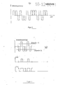
- FIG. 3 shows a typical sequence of pulses for transmitting the information to vehicles.
- the pulse diagram consists of sixteen pulses. These contain information about which receiver circuit is meant, the address, and whether to drive forward or backward. If a vehicle receives a valid, i.e. information addressed to its receiver, the travel current is switched to the motor for a fixed time. Smooth driving is achieved by periodically responding to the vehicle. The frequency determines the driving speed.
- the transmitted information is structured as follows:
- the pulse diagram begins with a sequence of eight pulses, which are always sent in the true or inverted form.
- the true sequence is decoded and noted as information "forward” in all receivers, the inverted sequence as "backward”.
- the end of this sequence which is referred to below as the "sync character" is the sign that the following 8 pulses are to be considered as addresses. This is compared with a pulse train impressed on the receiver circuit. If there is agreement, the direction of travel noted when the sync symbol appears and the current for. switched through a fixed time.
- the information sent is taken from the vehicle via the rails.
- the possibility of placing this on the rail in two different directions of travel means that the assignment between the receiver connections and the rails is undetermined.
- a pulse telegram is recorded either in its true or in its inverted form.
- the pulse source 5 sends the address one after the other in true and inverted form, each guided by a sync symbol.
- the user of the system can choose whether he wants to determine the direction of travel in relation to the vehicle. Then the sync symbol belonging to the direction of travel is sent with the true address and then both are inverted. Or he can choose the direction of travel based on the rail. Then one and the same sync character with the true and the inverted address is sent in succession.
- the solution is also possible that the vehicle can recognize the true and the inverted address at the same time. The choice of direction of travel does not result.
- FIG. 4 shows the detection of transmitted positive and negative pulses from the pulse diagram.
- the signal S 15 becomes 1 when the threshold 15 is exceeded and the signal S 16 becomes 1 when the threshold 16 is exceeded. If a DC voltage for operating a conventional model vehicle is superimposed on the pulse diagram, . Thresholds carried so that the threshold 15 is always above and the threshold 16 is always below the DC voltage mean. -
- FIG. 5 shows a circuit for converting the threshold signals S 15 and S 16 resulting from positive and negative pulses into a logical sequence.
- a transition from logic 0 to 1 occurs at the output at the end of a positive or negative pulse on the rail.
- the output of the gate 17 is connected to the dynamic clock input of the bistable memory 18, which responds to rising edges.
- the preparatory data input of the memory is connected to the signal S 15 .
- S15 1 during a positive pulse.
- Logical 1 is prepared at memory 18. At the end of the positive pulse, the positive edge is created at the clock input of the memory, so that 1 appears at the output of the memory.
- the memory 18 is followed by a serial-parallel, shifting shift register 19, to which the same clock is applied as the memory 18. At the output of the shift register, the pulse train sent is available as a parallel data word.
- the memory 18 is identical to the first memory element of the shift register.
Landscapes
- Toys (AREA)
- Remote Monitoring And Control Of Power-Distribution Networks (AREA)
Priority Applications (1)
| Application Number | Priority Date | Filing Date | Title |
|---|---|---|---|
| AT80108015T ATE11873T1 (de) | 1980-01-08 | 1980-12-18 | Einrichtung zur versorgung und zum steuern mehrerer elektrisch betriebener modellfahrzeuge. |
Applications Claiming Priority (2)
| Application Number | Priority Date | Filing Date | Title |
|---|---|---|---|
| DE19803000423 DE3000423A1 (de) | 1980-01-08 | 1980-01-08 | Verfahren zur gleichzeitigen selektiven uebertragung von digitaler information und elektrischer modellfahrzeuge auf einem stromkreis |
| DE3000423 | 1980-01-08 |
Publications (3)
| Publication Number | Publication Date |
|---|---|
| EP0031935A2 true EP0031935A2 (fr) | 1981-07-15 |
| EP0031935A3 EP0031935A3 (en) | 1981-07-22 |
| EP0031935B1 EP0031935B1 (fr) | 1985-02-20 |
Family
ID=6091652
Family Applications (1)
| Application Number | Title | Priority Date | Filing Date |
|---|---|---|---|
| EP80108015A Expired EP0031935B1 (fr) | 1980-01-08 | 1980-12-18 | Dispositif pour l'alimentation et la commande de plusieurs véhicules miniatures entrainés électriquement |
Country Status (3)
| Country | Link |
|---|---|
| EP (1) | EP0031935B1 (fr) |
| AT (1) | ATE11873T1 (fr) |
| DE (2) | DE3000423A1 (fr) |
Cited By (1)
| Publication number | Priority date | Publication date | Assignee | Title |
|---|---|---|---|---|
| EP0413979A3 (en) * | 1989-08-22 | 1991-09-25 | Peter Dipl.-Kfm. Doehler | Process and circuit arrangement to identify a model railway locomotive |
Family Cites Families (5)
| Publication number | Priority date | Publication date | Assignee | Title |
|---|---|---|---|---|
| DE2601790A1 (de) * | 1976-01-20 | 1977-07-21 | Bastian Dipl Ing Ingbert | Schaltungsanordnung zur versorgung und zum steuern mehrerer elektrisch betriebener modellfahrzeuge |
| GB2007895B (en) * | 1977-10-13 | 1982-02-10 | Rovex Ltd | Remote control systems and transmitters and receivers therefor |
| GB2014770B (en) * | 1978-02-20 | 1982-03-17 | Goddin L | Model railway system |
| GB2031624B (en) * | 1978-08-15 | 1982-03-31 | Rovex Ltd | Remote control of electrical devices |
| DE2904510A1 (de) * | 1979-02-07 | 1980-08-14 | Fraunhofer Ges Forschung | Digitalisiertes verfahren zur gleichzeitigen steuerung mehrerer elektrisch angetriebener modellfahrzeuge auf einem stromkreis |
-
1980
- 1980-01-08 DE DE19803000423 patent/DE3000423A1/de not_active Ceased
- 1980-12-18 DE DE8080108015T patent/DE3070233D1/de not_active Expired
- 1980-12-18 AT AT80108015T patent/ATE11873T1/de not_active IP Right Cessation
- 1980-12-18 EP EP80108015A patent/EP0031935B1/fr not_active Expired
Cited By (1)
| Publication number | Priority date | Publication date | Assignee | Title |
|---|---|---|---|---|
| EP0413979A3 (en) * | 1989-08-22 | 1991-09-25 | Peter Dipl.-Kfm. Doehler | Process and circuit arrangement to identify a model railway locomotive |
Also Published As
| Publication number | Publication date |
|---|---|
| DE3070233D1 (en) | 1985-03-28 |
| EP0031935B1 (fr) | 1985-02-20 |
| DE3000423A1 (de) | 1981-07-09 |
| EP0031935A3 (en) | 1981-07-22 |
| ATE11873T1 (de) | 1985-03-15 |
Similar Documents
| Publication | Publication Date | Title |
|---|---|---|
| DE69315903T2 (de) | Einrichtung und Verfahren zum erzwungenen Verteilen der Schaltverluste parallelgeschalteter Transistoren | |
| EP0616924B1 (fr) | Dispositif et procédé pour la transmission sous fil de données et d'énergie | |
| DE2013428C3 (de) | Anordnung zur uebertragung von daten im zeitmultiplexverfahren | |
| DE3318829A1 (de) | Fernsteuereinrichtung | |
| WO1984003672A1 (fr) | Procede pour augmenter le nombre de signaux pouvant etre transmis d'une station au sol a un vehicule sur rails | |
| DE3704590A1 (de) | Frequenzumformer | |
| DE1563971A1 (de) | Elektrisch betriebene Antriebseinrichtung | |
| DE2337442A1 (de) | Verfahren und schaltungsanordnung zum kombinieren eines analogen signals mit einem digitalen signal | |
| EP0031935A2 (fr) | Dispositif pour l'alimentation et la commande de plusieurs véhicules miniatures entrainés électriquement | |
| DE2305112A1 (de) | Spielzeugfahranlage zur gleichzeitigen steuerung mehrerer spielfahrzeuge auf einem einzigen stromkreis | |
| DE2846801A1 (de) | Steuerungs-system fuer modellfahrzeuge - insbesondere fuer auf gleisanlagen betriebene modellbahnzuege | |
| EP0017714B1 (fr) | Dispositif pour le contrôle simultané de plusieurs trains miniatures électriques sur une seule ligne d'alimentation | |
| DE3513170A1 (de) | Verfahren zum ansteuern ein- und ausschaltbarer leistungshalbleiterbauelemente und vorrichtung zur durchfuehrung des verfahrens | |
| DE102008052889A1 (de) | Verfahren und Vorrichtung für ein in ein Stromkabel integriertes Digitalsignal | |
| DE3025035A1 (de) | Verfahren und anordnung zum unabhaengigen betreiben mehrerer elektrischer triebfahrzeuge einer modell- und spielzeugeisenbahnanlage | |
| DE3232303C2 (fr) | ||
| EP0198263A2 (fr) | Montage pour la transmission de signaux numériques sans mise à la terre par l'intermédiaire de points de séparation | |
| DE19638872A1 (de) | Vorrichtung und Verfahren zur Datenübertragung | |
| DE1563594B2 (fr) | ||
| DE2502780A1 (de) | Steuerverfahren fuer elektrische modellbahnen | |
| DE2736522C2 (de) | Schaltungsanordnung zum Obertragen von Daten | |
| DE2011286A1 (de) | Fernsteuerungsanlage | |
| DE2903075C2 (de) | Verfahren und Einrichtung zur pulslängencodierten Fernübertragung | |
| DE102007036558A1 (de) | Übertragung von Informationen zwischen einem elektrischen Verbraucher und einem Betriebsmittel | |
| EP0840433B1 (fr) | Alimentation de tension pour le circuit de commande d'un commutateur dans un convertisseur avec circuit intermédiaire de tension |
Legal Events
| Date | Code | Title | Description |
|---|---|---|---|
| PUAI | Public reference made under article 153(3) epc to a published international application that has entered the european phase |
Free format text: ORIGINAL CODE: 0009012 |
|
| PUAL | Search report despatched |
Free format text: ORIGINAL CODE: 0009013 |
|
| AK | Designated contracting states |
Designated state(s): AT CH DE FR GB IT |
|
| AK | Designated contracting states |
Designated state(s): AT CH DE FR GB IT |
|
| 17P | Request for examination filed |
Effective date: 19810807 |
|
| ITF | It: translation for a ep patent filed | ||
| GRAA | (expected) grant |
Free format text: ORIGINAL CODE: 0009210 |
|
| AK | Designated contracting states |
Designated state(s): AT CH DE FR GB IT LI |
|
| REF | Corresponds to: |
Ref document number: 11873 Country of ref document: AT Date of ref document: 19850315 Kind code of ref document: T |
|
| REF | Corresponds to: |
Ref document number: 3070233 Country of ref document: DE Date of ref document: 19850328 |
|
| ET | Fr: translation filed | ||
| PLBE | No opposition filed within time limit |
Free format text: ORIGINAL CODE: 0009261 |
|
| STAA | Information on the status of an ep patent application or granted ep patent |
Free format text: STATUS: NO OPPOSITION FILED WITHIN TIME LIMIT |
|
| 26N | No opposition filed | ||
| REG | Reference to a national code |
Ref country code: CH Ref legal event code: PUE Owner name: GEBR. FLEISCHMANN |
|
| REG | Reference to a national code |
Ref country code: FR Ref legal event code: TP |
|
| REG | Reference to a national code |
Ref country code: GB Ref legal event code: 732 |
|
| ITPR | It: changes in ownership of a european patent |
Owner name: CESSIONE;GEBR. FLEISCHMANN |
|
| PGFP | Annual fee paid to national office [announced via postgrant information from national office to epo] |
Ref country code: AT Payment date: 19901116 Year of fee payment: 11 |
|
| PGFP | Annual fee paid to national office [announced via postgrant information from national office to epo] |
Ref country code: FR Payment date: 19901126 Year of fee payment: 11 |
|
| PGFP | Annual fee paid to national office [announced via postgrant information from national office to epo] |
Ref country code: CH Payment date: 19901127 Year of fee payment: 11 |
|
| PGFP | Annual fee paid to national office [announced via postgrant information from national office to epo] |
Ref country code: GB Payment date: 19901210 Year of fee payment: 11 |
|
| ITTA | It: last paid annual fee | ||
| PG25 | Lapsed in a contracting state [announced via postgrant information from national office to epo] |
Ref country code: GB Effective date: 19911218 Ref country code: AT Effective date: 19911218 |
|
| PG25 | Lapsed in a contracting state [announced via postgrant information from national office to epo] |
Ref country code: LI Effective date: 19911231 Ref country code: CH Effective date: 19911231 |
|
| GBPC | Gb: european patent ceased through non-payment of renewal fee | ||
| PG25 | Lapsed in a contracting state [announced via postgrant information from national office to epo] |
Ref country code: FR Effective date: 19920831 |
|
| REG | Reference to a national code |
Ref country code: CH Ref legal event code: PL |
|
| REG | Reference to a national code |
Ref country code: FR Ref legal event code: ST |
|
| PGFP | Annual fee paid to national office [announced via postgrant information from national office to epo] |
Ref country code: DE Payment date: 19971023 Year of fee payment: 18 |
|
| PG25 | Lapsed in a contracting state [announced via postgrant information from national office to epo] |
Ref country code: DE Free format text: LAPSE BECAUSE OF NON-PAYMENT OF DUE FEES Effective date: 19991001 |