EP0032024A2 - Verfahren zur Herstellung von Halbleitervorrichtungen, nach dem Verfahren hergestellte Vorrichtungen und Schaltungen und Artikel, die solche Vorrichtungen enthalten - Google Patents
Verfahren zur Herstellung von Halbleitervorrichtungen, nach dem Verfahren hergestellte Vorrichtungen und Schaltungen und Artikel, die solche Vorrichtungen enthalten Download PDFInfo
- Publication number
- EP0032024A2 EP0032024A2 EP80304585A EP80304585A EP0032024A2 EP 0032024 A2 EP0032024 A2 EP 0032024A2 EP 80304585 A EP80304585 A EP 80304585A EP 80304585 A EP80304585 A EP 80304585A EP 0032024 A2 EP0032024 A2 EP 0032024A2
- Authority
- EP
- European Patent Office
- Prior art keywords
- silicon
- layer
- silicon oxynitride
- oxynitride layer
- substrate
- Prior art date
- Legal status (The legal status is an assumption and is not a legal conclusion. Google has not performed a legal analysis and makes no representation as to the accuracy of the status listed.)
- Granted
Links
Images

Classifications
-
- H—ELECTRICITY
- H10—SEMICONDUCTOR DEVICES; ELECTRIC SOLID-STATE DEVICES NOT OTHERWISE PROVIDED FOR
- H10W—GENERIC PACKAGES, INTERCONNECTIONS, CONNECTORS OR OTHER CONSTRUCTIONAL DETAILS OF DEVICES COVERED BY CLASS H10
- H10W10/00—Isolation regions in semiconductor bodies between components of integrated devices
- H10W10/01—Manufacture or treatment
- H10W10/011—Manufacture or treatment of isolation regions comprising dielectric materials
- H10W10/012—Manufacture or treatment of isolation regions comprising dielectric materials using local oxidation of silicon [LOCOS]
-
- H—ELECTRICITY
- H10—SEMICONDUCTOR DEVICES; ELECTRIC SOLID-STATE DEVICES NOT OTHERWISE PROVIDED FOR
- H10P—GENERIC PROCESSES OR APPARATUS FOR THE MANUFACTURE OR TREATMENT OF DEVICES COVERED BY CLASS H10
- H10P14/00—Formation of materials, e.g. in the shape of layers or pillars
- H10P14/60—Formation of materials, e.g. in the shape of layers or pillars of insulating materials
- H10P14/61—Formation of materials, e.g. in the shape of layers or pillars of insulating materials using masks
-
- H—ELECTRICITY
- H10—SEMICONDUCTOR DEVICES; ELECTRIC SOLID-STATE DEVICES NOT OTHERWISE PROVIDED FOR
- H10P—GENERIC PROCESSES OR APPARATUS FOR THE MANUFACTURE OR TREATMENT OF DEVICES COVERED BY CLASS H10
- H10P14/00—Formation of materials, e.g. in the shape of layers or pillars
- H10P14/60—Formation of materials, e.g. in the shape of layers or pillars of insulating materials
- H10P14/63—Formation of materials, e.g. in the shape of layers or pillars of insulating materials characterised by the formation processes
- H10P14/6326—Deposition processes
- H10P14/6328—Deposition from the gas or vapour phase
- H10P14/6334—Deposition from the gas or vapour phase using decomposition or reaction of gaseous or vapour phase compounds, i.e. chemical vapour deposition
- H10P14/6336—Deposition from the gas or vapour phase using decomposition or reaction of gaseous or vapour phase compounds, i.e. chemical vapour deposition in the presence of a plasma [PECVD]
-
- H—ELECTRICITY
- H10—SEMICONDUCTOR DEVICES; ELECTRIC SOLID-STATE DEVICES NOT OTHERWISE PROVIDED FOR
- H10P—GENERIC PROCESSES OR APPARATUS FOR THE MANUFACTURE OR TREATMENT OF DEVICES COVERED BY CLASS H10
- H10P14/00—Formation of materials, e.g. in the shape of layers or pillars
- H10P14/60—Formation of materials, e.g. in the shape of layers or pillars of insulating materials
- H10P14/69—Inorganic materials
- H10P14/692—Inorganic materials composed of oxides, glassy oxides or oxide-based glasses
- H10P14/6921—Inorganic materials composed of oxides, glassy oxides or oxide-based glasses containing silicon
- H10P14/6922—Inorganic materials composed of oxides, glassy oxides or oxide-based glasses containing silicon the material containing Si, O and at least one of H, N, C, F or other non-metal elements, e.g. SiOC, SiOC:H or SiONC
- H10P14/6927—Inorganic materials composed of oxides, glassy oxides or oxide-based glasses containing silicon the material containing Si, O and at least one of H, N, C, F or other non-metal elements, e.g. SiOC, SiOC:H or SiONC the material being a silicon oxynitride, e.g. SiON or SiON:H
-
- H—ELECTRICITY
- H10—SEMICONDUCTOR DEVICES; ELECTRIC SOLID-STATE DEVICES NOT OTHERWISE PROVIDED FOR
- H10W—GENERIC PACKAGES, INTERCONNECTIONS, CONNECTORS OR OTHER CONSTRUCTIONAL DETAILS OF DEVICES COVERED BY CLASS H10
- H10W10/00—Isolation regions in semiconductor bodies between components of integrated devices
- H10W10/10—Isolation regions comprising dielectric materials
- H10W10/13—Isolation regions comprising dielectric materials formed using local oxidation of silicon [LOCOS], e.g. sealed interface localised oxidation [SILO] or side-wall mask isolation [SWAMI]
-
- H—ELECTRICITY
- H10—SEMICONDUCTOR DEVICES; ELECTRIC SOLID-STATE DEVICES NOT OTHERWISE PROVIDED FOR
- H10P—GENERIC PROCESSES OR APPARATUS FOR THE MANUFACTURE OR TREATMENT OF DEVICES COVERED BY CLASS H10
- H10P14/00—Formation of materials, e.g. in the shape of layers or pillars
- H10P14/60—Formation of materials, e.g. in the shape of layers or pillars of insulating materials
- H10P14/63—Formation of materials, e.g. in the shape of layers or pillars of insulating materials characterised by the formation processes
- H10P14/6302—Non-deposition formation processes
- H10P14/6304—Formation by oxidation, e.g. oxidation of the substrate
- H10P14/6306—Formation by oxidation, e.g. oxidation of the substrate of the semiconductor materials
- H10P14/6308—Formation by oxidation, e.g. oxidation of the substrate of the semiconductor materials of Group IV semiconductors
- H10P14/6309—Formation by oxidation, e.g. oxidation of the substrate of the semiconductor materials of Group IV semiconductors of silicon in uncombined form, i.e. pure silicon
Definitions
- the present invention relates to a process for producing a semiconductor device.
- the selective oxidation process comprises the steps of forming a silicon oxide layer on a semiconductor substrate, forming a silicon nitride layer on the oxide layer, selectively etching the nitride and oxide layers to expose a portion of the semiconductor substrate, and oxidizing the exposed portion of the semiconductor substrate.
- the above-mentioned selective oxidation process is explained in detail with reference to Figs. lA, 1B and 1C.
- a silicon dioxide (Si0 2 ) layer 2 (Fig. lA) having a thickness of approximately 50 nm (i.e. 500 angstroms) is formed on a silicon (Si) substrate (i.e. a single crystalline silicon wafer) 1 by a conventional thermal oxidation method or chemical vapor deposition (CVD) method. Then, a silicon nitride (Si 3 N 4 ) layer 3 having a thickness of - approximately 100 nm is deposited on the silicon oxide layer 2 by a conventional CVD method, as illustrated in Fig. lA.
- the silicon nitride layer 3 and silicon dioxide layer 2 are selectively etched by a photoetching method, as illustrated in Fig. 1B. Namely, a photoresist layer (not illustrated) applied on the silicon nitride layer 3, is exposed and is developed to form a patterned resist mask. An unmasked portion of the silicon nitride layer is etched by a hot phosphoric acid solution and then an exposed portion of the silicon dioxide layer 2 is etched by a hydrofluoric acid solution to expose a portion of the silicon substrate 1.
- the silicon substrate 1 with the patterned silicon dioxide layer 2 and silicon nitride layer 3 is subjected to a conventional thermal oxidation treatment to convert the exposed portion of the silicon substrate 1 into a relatively thick silicon dioxide layer 4, i.e. a field oxide layer or an isolation oxide layer, as illustrated in Fig. 1C.
- a relatively thick silicon dioxide layer 4 i.e. a field oxide layer or an isolation oxide layer, as illustrated in Fig. 1C.
- an upper portion of the silicon nitride layer 3 is changed into a silicon dioxide layer 5 having a thickness of approximately 50 nm during the thermal oxidation treatment.
- SiON silicon oxynitride
- CVD chemical vapor deposition
- the silicon oxynitride layer is preferable to the silicon nitride (Si 3 N 4 ) layer.
- the etchrate of the silicon oxynitride is larger than that of the silicon dioxide, so that a field oxide layer to be formed is(less markedly) remarkably etched during a removal of the silicon oxynitride layer by etching.
- the present invention provides a process for producing a semiconductor device comprising the step of forming a silicon oxynitride (SiON) layer on a semiconductor substrate by a plasma chemical vapor deposition method instead of both a silicon dioxide (Si0 2 ) layer and a silicon nitride (Si 3 N 4 ) layer which are formed in a conventional selective oxidation process.
- SiON silicon oxynitride
- the composition of the silicon oxynitride i.e., the symbols "1", “m” and “n” in the chemical formula (Si l O m N n ) of silicon oxynitride can vary in accordance with the gases, e.g monsilane (SiH 4 ) gas, nitrous oxide (N 2 0) gas and ammonia (NH 3 ) gas which are fed into a plasma CVD apparatus.
- the gases e.g monsilane (SiH 4 ) gas, nitrous oxide (N 2 0) gas and ammonia (NH 3 ) gas which are fed into a plasma CVD apparatus.
- the silicon oxynitride layer is deposited directly on a silicon substrate, when the substrate is heated for a thermal oxidation treatment, slight internal stress occurs at the boundary of the silicon oxynitride layer and the substrate.
- Such slight internal stress does not bring about the above-mentioned disadvantages i.e. cracks in the silicon oxynitride layer and/or crystal faults in the silicon substrate.
- a thermal oxidation treatment to form a relatively thick silicon dioxide layer (e.g. a field oxide layer)
- a so-called bird's beak smaller than that formed in the prior art is formed.
- the bird's beak formed according to the process of the present invention is one-third to one-half of that formed according the conventional selective oxidation process.
- the silicon oxynitride layer by a hydrofluoric acid solution which is used for etching a silicon dioxide layer. It is preferable to form the silicon oxynitride layer having a thickness of from 100 to 300 nm. When a thickness of the silicon oxynitride layer is below 100 nm, the silicon oxynitride layer does not sufficiently serve as a barrier to oxidation during the thermal oxidation treatment. If a thickness of the silicon oxynitride layer is above 300 nm, it is possible to form cracks in the oxynitride layer during the thermal oxidation treatment.
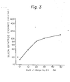
- etchrate of the silicon oxynitride layer deposited in the above mentioned manner is shown in Fig. 3.
- the solid line in Fig. 3 has been determined on the basis of experiments carried out under the following conditions.
- the deposited silicon oxynitride layers were etched by a diluted hydrofluoric acid solution (1.25% HF) to obtain the etchrate of the layers.
- the etchrate of a silicon dioxide layer with the same etching solution is approximately 20 nm/min and is indicated by the symbol "X" in Fig. 3.
- the etchrate of the former oxynitride layer is 40 nm/min, while that of the latter oxynitride layer is 10 nm/min with the diluted hydrofluoric acid solution (1.25% HF).
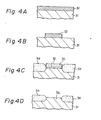
- a silicon oxynitride layer 32 having a thickness of approximately 200 nm is deposited by the above-mentioned plasma chemical vapor deposition treatment, as illustrated in Fig. 4A.
- the depositing conditions are the same as those of the above-mentioned experiments except that the temperature of the substrate is 350°C. In this case, the ratio of N 2 0 to (NH 3 +N 2 O) is 20%. Since the etchrate of silicon oxynitride is higher than that of silicon nitride, the silicon oxynitride layer to be deposited is relatively thick as compared with a silicon nitride layer used in a conventional selective oxidation process.
- the deposited silicon oxynitride layer 32 is selectively removed by a conventional photoetching method to expose a portion of the silicon substrate 31, as illustrated in Fig. 4B.
- a diluted hydrofluoric acid solution (1.25% HF) is used as an etchant for silicon oxynitride.
- the silicon substrate 31 with the remaining silicon oxynitride layer 32 is subjected to a thermal oxidation treatment at a temperature of 1,000°C or more to convert the exposed portion of the silicon substrate 31 into a silicon dioxide layer 34 having a thickness of 1.2 ⁇ m, as illustrated in Fig. 4C.
- the upper portion of the silicon oxynitride layer 32 is simultaneously oxidized to change it into a silicon dioxide layer 35 having a thickness of approximately 100 nm.
- the obtained silicon substrate is subjected to an etching treatment using a diluted hydrofluoric acid solution (1.25% HF) to remove the silicon oxynitride layer 32 and the silicon dioxide layer 35 formed thereon, as illustrated in Fig. 4D.
- a diluted hydrofluoric acid solution 1.25% HF
- the thickness of the layer 34 is decreased to approximately 1 ⁇ m.
- the silicon dioxide layer 34 may be used as an isolation oxide layer for dielectric isolation in a semiconductor device.
- a portion 36 of the silicon substrate 31 is exposed.
- a semiconductor element or a passive element should be formed in the exposed portion 36 .in accordance with a suitable forming process.
- the present invention is not restricted to the embodiment described and that modifications are possible for a person with ordinary skill in the art without departing from the scope of this invention.
- the process of the invention may be carried out on a substrate, for example silicon, to portions of which impurities have been introduced.
- the introduction of impurities may be, for example, by an ion implantation method.
- a particularly preferred feature of the invention is the inclusion of an additional process step comprising removing the silicon oxynitride which remains after the oxidation step. It is preferred, too, to etch the silicon oxynitride layer using hydrofluoric acid.
- etching is meant to include any means of removing the oxynitride layer so as to achieve the desired end result.
- the gases which are employed in the plasma chemical vapor deposition method comprise silane, ammonia and nitrous oxide.
- theinvention includes within its scope a selective oxidation process for producing a semiconductor device which comprises the step of depositing a silicon oxynitride layer directly on a silicon substrate by a plasma chemical vapor deposition method. After a selective oxidation of the silicon substrate, the silicon oxynitride layer is removed.
- the invention also includes semiconductor devices formed by the defined process, circuits including such devices and articles including such circuits.
Landscapes
- Local Oxidation Of Silicon (AREA)
- Formation Of Insulating Films (AREA)
Applications Claiming Priority (2)
| Application Number | Priority Date | Filing Date | Title |
|---|---|---|---|
| JP17003079A JPS5693344A (en) | 1979-12-26 | 1979-12-26 | Manufacture of semiconductor device |
| JP170030/79 | 1979-12-26 |
Publications (3)
| Publication Number | Publication Date |
|---|---|
| EP0032024A2 true EP0032024A2 (de) | 1981-07-15 |
| EP0032024A3 EP0032024A3 (en) | 1984-06-13 |
| EP0032024B1 EP0032024B1 (de) | 1987-08-19 |
Family
ID=15897295
Family Applications (1)
| Application Number | Title | Priority Date | Filing Date |
|---|---|---|---|
| EP80304585A Expired EP0032024B1 (de) | 1979-12-26 | 1980-12-18 | Verfahren zur Herstellung von Halbleitervorrichtungen, nach dem Verfahren hergestellte Vorrichtungen und Schaltungen und Artikel, die solche Vorrichtungen enthalten |
Country Status (4)
| Country | Link |
|---|---|
| US (1) | US4363868A (de) |
| EP (1) | EP0032024B1 (de) |
| JP (1) | JPS5693344A (de) |
| DE (1) | DE3072012D1 (de) |
Cited By (2)
| Publication number | Priority date | Publication date | Assignee | Title |
|---|---|---|---|---|
| EP0071203A3 (en) * | 1981-07-30 | 1985-06-19 | International Business Machines Corporation | Mask for thermal oxidation and method of forming dielectric isolation surrounding regions |
| EP0340474A3 (de) * | 1988-04-26 | 1989-11-15 | Seiko Instruments Inc. | Verfahren zur Herstellung von Halbleiteranordnungen mit unterschiedlicher Oxidschichtdicke |
Families Citing this family (25)
| Publication number | Priority date | Publication date | Assignee | Title |
|---|---|---|---|---|
| US4419385A (en) * | 1981-09-24 | 1983-12-06 | Hughes Aircraft Company | Low temperature process for depositing an oxide dielectric layer on a conductive surface and multilayer structures formed thereby |
| JPS6010644A (ja) * | 1983-06-30 | 1985-01-19 | Toshiba Corp | 半導体装置の製造方法 |
| US4472459A (en) * | 1983-10-24 | 1984-09-18 | Rca Corporation | Local oxidation of silicon substrate using LPCVD silicon nitride |
| US4527325A (en) * | 1983-12-23 | 1985-07-09 | International Business Machines Corporation | Process for fabricating semiconductor devices utilizing a protective film during high temperature annealing |
| US4543271A (en) * | 1984-07-02 | 1985-09-24 | Hughes Aircraft Company | Silicon oxynitride material and photochemical process for forming same |
| JPH0752718B2 (ja) * | 1984-11-26 | 1995-06-05 | 株式会社半導体エネルギー研究所 | 薄膜形成方法 |
| US6786997B1 (en) * | 1984-11-26 | 2004-09-07 | Semiconductor Energy Laboratory Co., Ltd. | Plasma processing apparatus |
| US4631219A (en) * | 1985-01-31 | 1986-12-23 | International Business Machines Corporation | Growth of bird's beak free semi-rox |
| US4637895A (en) * | 1985-04-01 | 1987-01-20 | Energy Conversion Devices, Inc. | Gas mixtures for the vapor deposition of semiconductor material |
| US4705760A (en) * | 1986-01-16 | 1987-11-10 | Rca Corporation | Preparation of a surface for deposition of a passinating layer |
| JPS62172733A (ja) * | 1986-01-16 | 1987-07-29 | ア−ルシ−エ− コ−ポレ−ション | 半導体基体 |
| US4775550A (en) * | 1986-06-03 | 1988-10-04 | Intel Corporation | Surface planarization method for VLSI technology |
| US4725560A (en) * | 1986-09-08 | 1988-02-16 | International Business Machines Corp. | Silicon oxynitride storage node dielectric |
| NL8603111A (nl) * | 1986-12-08 | 1988-07-01 | Philips Nv | Werkwijze voor het vervaardigen van een halfgeleiderinrichting waarbij een siliciumplak aan zijn oppervlak wordt voorzien van veldoxidegebieden. |
| JP2918892B2 (ja) * | 1988-10-14 | 1999-07-12 | 株式会社日立製作所 | プラズマエッチング処理方法 |
| DE69405438T2 (de) * | 1993-03-24 | 1998-04-02 | At & T Corp | Verfahren zur Bildung dielektrischer Oxynitridschichten bei der Herstellung integrierter Schaltungen |
| KR960005553B1 (ko) * | 1993-03-31 | 1996-04-26 | 현대전자산업주식회사 | 필드산화막 형성 방법 |
| US5541141A (en) * | 1995-02-27 | 1996-07-30 | Hyundai Electronics Industries Co., Ltd. | Method for forming an oxynitride film in a semiconductor device |
| US5989957A (en) * | 1997-05-21 | 1999-11-23 | Advanced Micro Devices | Process for fabricating semiconductor memory device with high data retention including silicon oxynitride etch stop layer formed at high temperature with low hydrogen ion concentration |
| US6121133A (en) | 1997-08-22 | 2000-09-19 | Micron Technology, Inc. | Isolation using an antireflective coating |
| US6294459B1 (en) * | 1998-09-03 | 2001-09-25 | Micron Technology, Inc. | Anti-reflective coatings and methods for forming and using same |
| US6703283B1 (en) | 1999-02-04 | 2004-03-09 | International Business Machines Corporation | Discontinuous dielectric interface for bipolar transistors |
| US6989579B2 (en) * | 2001-12-26 | 2006-01-24 | Lucent Technologies Inc. | Adhering layers to metals with dielectric adhesive layers |
| JP2004235548A (ja) * | 2003-01-31 | 2004-08-19 | Nec Electronics Corp | 半導体装置およびその製造方法 |
| US11427731B2 (en) | 2018-03-23 | 2022-08-30 | Teledyne Micralyne, Inc. | Adhesive silicon oxynitride film |
Family Cites Families (10)
| Publication number | Priority date | Publication date | Assignee | Title |
|---|---|---|---|---|
| GB1104935A (en) * | 1964-05-08 | 1968-03-06 | Standard Telephones Cables Ltd | Improvements in or relating to a method of forming a layer of an inorganic compound |
| US3422321A (en) * | 1966-06-20 | 1969-01-14 | Sperry Rand Corp | Oxygenated silicon nitride semiconductor devices and silane method for making same |
| CH516871A (it) * | 1969-07-30 | 1971-12-15 | Soc Gen Semiconduttori Spa | Procedimento per ottenere dispositivi a semiconduttore con minimi dislivelli in superficie, e dispositivo a semiconduttore ottenuto mediante detto procedimento |
| US3655438A (en) * | 1969-10-20 | 1972-04-11 | Int Standard Electric Corp | Method of forming silicon oxide coatings in an electric discharge |
| CA1001771A (en) * | 1973-01-15 | 1976-12-14 | Fairchild Camera And Instrument Corporation | Method of mos transistor manufacture and resulting structure |
| JPS5333053B2 (de) * | 1973-08-15 | 1978-09-12 | ||
| US3886000A (en) * | 1973-11-05 | 1975-05-27 | Ibm | Method for controlling dielectric isolation of a semiconductor device |
| JPS5559729A (en) * | 1978-10-27 | 1980-05-06 | Fujitsu Ltd | Forming method of semiconductor surface insulating film |
| JPS5642377A (en) * | 1979-09-14 | 1981-04-20 | Fujitsu Ltd | Ultraviolet ray erasable type rewritable read-only memory |
| US4289797A (en) * | 1979-10-11 | 1981-09-15 | Western Electric Co., Incorporated | Method of depositing uniform films of Six Ny or Six Oy in a plasma reactor |
-
1979
- 1979-12-26 JP JP17003079A patent/JPS5693344A/ja active Pending
-
1980
- 1980-12-18 DE DE8080304585T patent/DE3072012D1/de not_active Expired
- 1980-12-18 EP EP80304585A patent/EP0032024B1/de not_active Expired
- 1980-12-23 US US06/219,494 patent/US4363868A/en not_active Expired - Lifetime
Cited By (3)
| Publication number | Priority date | Publication date | Assignee | Title |
|---|---|---|---|---|
| EP0071203A3 (en) * | 1981-07-30 | 1985-06-19 | International Business Machines Corporation | Mask for thermal oxidation and method of forming dielectric isolation surrounding regions |
| EP0340474A3 (de) * | 1988-04-26 | 1989-11-15 | Seiko Instruments Inc. | Verfahren zur Herstellung von Halbleiteranordnungen mit unterschiedlicher Oxidschichtdicke |
| US4971923A (en) * | 1988-04-26 | 1990-11-20 | Seiko Instruments Inc. | Method of making semiconductor device with different oxide film thicknesses |
Also Published As
| Publication number | Publication date |
|---|---|
| EP0032024B1 (de) | 1987-08-19 |
| EP0032024A3 (en) | 1984-06-13 |
| US4363868A (en) | 1982-12-14 |
| JPS5693344A (en) | 1981-07-28 |
| DE3072012D1 (en) | 1987-09-24 |
Similar Documents
| Publication | Publication Date | Title |
|---|---|---|
| EP0032024B1 (de) | Verfahren zur Herstellung von Halbleitervorrichtungen, nach dem Verfahren hergestellte Vorrichtungen und Schaltungen und Artikel, die solche Vorrichtungen enthalten | |
| US8703005B2 (en) | Methods for removing dielectric materials | |
| US5089432A (en) | Polycide gate MOSFET process for integrated circuits | |
| US6013575A (en) | Method of selectively depositing a metal film | |
| EP0023146A2 (de) | Verfahren zur Herstellung einer Halbleiteranordnung, in der erste und zweite Schichten geformt sind | |
| US5130266A (en) | Polycide gate MOSFET process for integrated circuits | |
| JP2903884B2 (ja) | 半導体装置の製法 | |
| US4585515A (en) | Formation of conductive lines | |
| JP3267257B2 (ja) | 半導体装置の製造方法 | |
| US5747357A (en) | Modified poly-buffered isolation | |
| JPH0645275A (ja) | 半導体装置の製造方法 | |
| EP0366013A2 (de) | Selektive Dielektrikumsablagerung auf Horizontalstrukturen eines IC-Bauelementes | |
| EP0278159A2 (de) | Verfahren zur Herstellung einer Halbleiteranordnung mit einer Isolationsstruktur | |
| JP2522389B2 (ja) | 半導体装置の製造方法 | |
| JPH0799178A (ja) | 半導体装置の製造方法 | |
| JPS5943549A (ja) | アルミニウム配線層の形成方法 | |
| JPS5931215B2 (ja) | 絶縁層の形成方法 | |
| JPH0376577B2 (de) | ||
| JPH02181918A (ja) | 半導体装置の製造方法 | |
| KR940007540B1 (ko) | 반도체 장치의 소자격리방법 | |
| JPH0578193B2 (de) | ||
| JPH02128422A (ja) | 半導体装置の製造方法 | |
| JPH04107924A (ja) | 半導体装置の製造方法 | |
| JPH09266170A (ja) | 半導体装置の製造方法 | |
| JPH01265536A (ja) | 半導体集積回路における素子分離領域の形成方法 |
Legal Events
| Date | Code | Title | Description |
|---|---|---|---|
| PUAI | Public reference made under article 153(3) epc to a published international application that has entered the european phase |
Free format text: ORIGINAL CODE: 0009012 |
|
| AK | Designated contracting states |
Designated state(s): DE FR GB NL |
|
| RBV | Designated contracting states (corrected) |
Designated state(s): DE FR GB NL |
|
| 17P | Request for examination filed |
Effective date: 19811029 |
|
| PUAL | Search report despatched |
Free format text: ORIGINAL CODE: 0009013 |
|
| AK | Designated contracting states |
Designated state(s): DE FR GB NL |
|
| 17Q | First examination report despatched |
Effective date: 19860429 |
|
| GRAA | (expected) grant |
Free format text: ORIGINAL CODE: 0009210 |
|
| AK | Designated contracting states |
Kind code of ref document: B1 Designated state(s): DE FR GB |
|
| ET | Fr: translation filed | ||
| REF | Corresponds to: |
Ref document number: 3072012 Country of ref document: DE Date of ref document: 19870924 |
|
| PLBE | No opposition filed within time limit |
Free format text: ORIGINAL CODE: 0009261 |
|
| STAA | Information on the status of an ep patent application or granted ep patent |
Free format text: STATUS: NO OPPOSITION FILED WITHIN TIME LIMIT |
|
| 26N | No opposition filed | ||
| PGFP | Annual fee paid to national office [announced via postgrant information from national office to epo] |
Ref country code: GB Payment date: 19930921 Year of fee payment: 14 |
|
| PGFP | Annual fee paid to national office [announced via postgrant information from national office to epo] |
Ref country code: FR Payment date: 19931230 Year of fee payment: 14 |
|
| PGFP | Annual fee paid to national office [announced via postgrant information from national office to epo] |
Ref country code: DE Payment date: 19940224 Year of fee payment: 14 |
|
| PG25 | Lapsed in a contracting state [announced via postgrant information from national office to epo] |
Ref country code: GB Effective date: 19941218 |
|
| GBPC | Gb: european patent ceased through non-payment of renewal fee |
Effective date: 19941218 |
|
| PG25 | Lapsed in a contracting state [announced via postgrant information from national office to epo] |
Ref country code: FR Effective date: 19950831 |
|
| PG25 | Lapsed in a contracting state [announced via postgrant information from national office to epo] |
Ref country code: DE Effective date: 19950901 |
|
| REG | Reference to a national code |
Ref country code: FR Ref legal event code: ST |