EP0032676A2 - Installation de chauffage pour cabine de conduite - Google Patents
Installation de chauffage pour cabine de conduite Download PDFInfo
- Publication number
- EP0032676A2 EP0032676A2 EP81100071A EP81100071A EP0032676A2 EP 0032676 A2 EP0032676 A2 EP 0032676A2 EP 81100071 A EP81100071 A EP 81100071A EP 81100071 A EP81100071 A EP 81100071A EP 0032676 A2 EP0032676 A2 EP 0032676A2
- Authority
- EP
- European Patent Office
- Prior art keywords
- line
- valve
- liquid
- heat exchanger
- return line
- Prior art date
- Legal status (The legal status is an assumption and is not a legal conclusion. Google has not performed a legal analysis and makes no representation as to the accuracy of the status listed.)
- Granted
Links
Images


Classifications
-
- F—MECHANICAL ENGINEERING; LIGHTING; HEATING; WEAPONS; BLASTING
- F24—HEATING; RANGES; VENTILATING
- F24D—DOMESTIC- OR SPACE-HEATING SYSTEMS, e.g. CENTRAL HEATING SYSTEMS; DOMESTIC HOT-WATER SUPPLY SYSTEMS; ELEMENTS OR COMPONENTS THEREFOR
- F24D7/00—Central heating systems employing heat-transfer fluids not covered by groups F24D1/00 - F24D5/00, e.g. oil, salt or gas
-
- B—PERFORMING OPERATIONS; TRANSPORTING
- B60—VEHICLES IN GENERAL
- B60H—ARRANGEMENTS OF HEATING, COOLING, VENTILATING OR OTHER AIR-TREATING DEVICES SPECIALLY ADAPTED FOR PASSENGER OR GOODS SPACES OF VEHICLES
- B60H1/00—Heating, cooling or ventilating devices
- B60H1/02—Heating, cooling or ventilating devices the heat being derived from the propulsion plant
- B60H1/14—Heating, cooling or ventilating devices the heat being derived from the propulsion plant other than from cooling liquid of the plant
-
- B—PERFORMING OPERATIONS; TRANSPORTING
- B60—VEHICLES IN GENERAL
- B60H—ARRANGEMENTS OF HEATING, COOLING, VENTILATING OR OTHER AIR-TREATING DEVICES SPECIALLY ADAPTED FOR PASSENGER OR GOODS SPACES OF VEHICLES
- B60H1/00—Heating, cooling or ventilating devices
- B60H1/22—Heating, cooling or ventilating devices the heat source being other than the propulsion plant
-
- F—MECHANICAL ENGINEERING; LIGHTING; HEATING; WEAPONS; BLASTING
- F24—HEATING; RANGES; VENTILATING
- F24V—COLLECTION, PRODUCTION OR USE OF HEAT NOT OTHERWISE PROVIDED FOR
- F24V40/00—Production or use of heat resulting from internal friction of moving fluids or from friction between fluids and moving bodies
- F24V40/10—Production or use of heat resulting from internal friction of moving fluids or from friction between fluids and moving bodies the fluid passing through restriction means
Definitions
- the invention relates to a device for heating an operating cabin of a machine which is driven by an internal combustion engine, in particular the driver's cab of a vehicle, with a hydraulic pump driven by the internal combustion engine, which comes from the oil pan, the oil collecting container or the like. removes oil from the internal combustion engine, with a working element, for example a throttle, which can be connected to the hydraulic pump by a pressure line, and with a liquid-air heat exchanger in the cab, which can be connected to the working element by a pressure line and is connected to the oil pan by a return line is.
- a working element for example a throttle
- a liquid-air heat exchanger in the cab which can be connected to the working element by a pressure line and is connected to the oil pan by a return line is.
- a device for heating the operating cabin of a vehicle with a heat exchanger that uses the heat of the lubricating oil is known (DE-PS 26 23 621).
- This arrangement has the disadvantage that heating is only available when the engine is low in operation and therefore only to a sufficient extent when the engine is under load. In principle, this problem occurs in the same way with air-cooled and water-cooled internal combustion engines.
- the invention has for its object to release mechanically supplied energy with the largest possible proportion directly for heating the control cabin in the heat exchanger.
- the object is achieved according to the invention in that an adjustable or regulated flow divider is arranged either in the return line between the liquid-air heat exchanger and the collecting container or in the supply line between the working element and the liquid-air heat exchanger and with a branch into a short-circuit line to the suction side of the high-pressure feed pump flows.
- the amount of heat generated in the throttle causes an increase in temperature in the unbranched circuit, which generates an increased temperature gradient at the heat exchanger, so that a contribution is made to the heating and at the same time the amount of oil in the oil sump and the engine components is heated. This applies to the warm-up phase and for all operating states in which the lubricating oil temperature in the oil sump is below the return temperature from the heat exchanger, such as. B. with longer idle periods and lower outside temperature.
- the flow divider which is arranged in front of or behind the liquid-air heat exchanger, a short-circuit line to a small circuit with high-pressure feed pump, working element and, if necessary Has liquid-air heat exchanger in which a portion is circulated several times for accelerated heating. If the temperature of the filling of the collecting container has risen, in particular above the return temperature from this small circuit, the flow divider closes the short-circuit line and the heat supplied to the collecting container contributes to the heating.
- Various temperature or temperature difference-dependent control elements can be used to control the flow divider.
- a liquid-liquid heat exchanger can be used according to the invention in the lines from and to the collecting container, which causes the flow of heating medium to be preheated if the return temperature rises above the supply temperature.
- a bypass and various options for regulating it are provided.
- the working element is designed as a variable throttle, the throttle gap of which is set as a function of the pressure conditions at the throttle.
- a servo element acts on the gap in the closing direction together with a spring, which is connected on the one hand via a bore with a small cross section to the pressure line in front of the throttle point and on the other hand via a line provided with an adjustment valve to the collecting container. By adjusting the flow rate in the adjustment valve, the pressure in the servo element can be varied between the value upstream of the throttle and that in the collection container.
- the shut-off valve and the adjustment valve can be combined to form a manually operated control element which connects the adjustment ranges of both.
- the throttle is first acted upon by closing the shut-off valve and then the spring pressure against the throttle gap is increasingly increased by the increasing pressure in the servo element by closing the adjusting valve. This increases the power loss and thus the heat generation.
- the work element, flow divider, shut-off valve and adjusting valve are housed together in several or all in one housing.
- the heating air flow can also be regulated, in particular in the form that it is supplied to the room or the environment to be heated with a variable proportion with an unchanged volume flow.
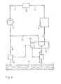
- Fig. 1 the heating system with a collecting container 1, a high pressure feed pump 2, a working element 3, a liquid-air heat exchanger 4 and a flow divider 5 is shown.
- the high-pressure feed pump 2 is connected to the container 1 through a suction line 6 and connected to the liquid-air heat exchanger through a Vorlauiannon 7, in which the working element 3 is arranged.
- a return line 8 leads from the liquid-air heat exchanger 4 to the collecting container 1.
- the flow divider 5 is arranged in the return line 8 in the embodiment shown and that a branch into the short-circuit line 9, which in turn opens into the suction line 6.
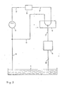
- Fig. 2 two temperature sensors 10 and 11 are arranged in the intake and return lines 6, 8, which are connected to a comparison point 1.2, which controls the flow divider 5.
- the arrangement of the components corresponds to FIG. 1.
- the flow divider 5 is arranged in the flow line 7 between the working element 3 and liquid-air heat exchanger 4. Otherwise, the design corresponds to that of FIG. 1.
- FIG. 4 shows a heating system with a liquid-liquid heat exchanger 13 which is arranged on the one hand in the intake line 6 and on the other hand in the return line 8. Parallel to the liquid-liquid heat exchanger 13 is a bypass 14 in the return flow, which is controlled by a three-way valve 15 depending on the temperature.
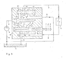
- FIG. 5 shows a heating system with a working element designed as a variable throttle in combination with a shut-off and adjusting valve, in whose housing is also integrated with the flow divider.
- the Abspcrr- and adjustment valve is provided with a pull rod 18, which is shown in three characteristic positions. In position “1”, the relief line 19 and the connecting line 20 are both open. At the transition from position “1" to position “2”, the shut-off valve 21 is closed, the adjusting valve 22 is still open. The heating medium flow flows through the throttle gap. The pressure in the servo element 25 behind the valve body 23 corresponds to that in the collecting container 1. When changing from position "2" to position "3", the adjusting valve 22 is also closed.
- the pressure in the servo element 25 adjusts to the amount in the feed line 7 upstream of the throttle.
- the throttle gap 26 there is a balance between the pressure of the heating medium in front of the throttle and the sum of the contact pressure of the spring 27 and the pressure in the servo element 25.
- the heating medium flow is passed to the flow divider 5.
- This has a temperature-dependent source body 29, which adjusts a slide 30 against the restoring force of a spring 31 so that either the feed line 7 to the liquid-air heat exchanger 4 or the short-circuit line 9 to the high-pressure feed pump 2 are released.
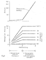
- FIG. 6 shows in two diagrams the dependence of the heating medium flow - here especially the oil flow - to the liquid-air heat exchanger and the heating medium pressure - here especially the oil pressure - in front of the throttle point from the position of the shut-off and adjustment valve with the heating medium temperature, here as the oil temperature after the pump, as a parameter.
Landscapes
- Engineering & Computer Science (AREA)
- Physics & Mathematics (AREA)
- Thermal Sciences (AREA)
- Mechanical Engineering (AREA)
- Chemical & Material Sciences (AREA)
- Combustion & Propulsion (AREA)
- General Engineering & Computer Science (AREA)
- Air-Conditioning For Vehicles (AREA)
- Central Heating Systems (AREA)
- Fluid-Pressure Circuits (AREA)
- Harvester Elements (AREA)
- Body Structure For Vehicles (AREA)
- Forklifts And Lifting Vehicles (AREA)
Priority Applications (1)
| Application Number | Priority Date | Filing Date | Title |
|---|---|---|---|
| AT81100071T ATE6352T1 (de) | 1980-01-17 | 1981-01-08 | Einrichtung zum beheizen einer bedienungskabine. |
Applications Claiming Priority (2)
| Application Number | Priority Date | Filing Date | Title |
|---|---|---|---|
| DE3001564 | 1980-01-17 | ||
| DE19803001564 DE3001564A1 (de) | 1980-01-17 | 1980-01-17 | Einrichtung zum beheizen einer bedienungskabine |
Publications (3)
| Publication Number | Publication Date |
|---|---|
| EP0032676A2 true EP0032676A2 (fr) | 1981-07-29 |
| EP0032676A3 EP0032676A3 (en) | 1981-08-12 |
| EP0032676B1 EP0032676B1 (fr) | 1984-02-22 |
Family
ID=6092287
Family Applications (1)
| Application Number | Title | Priority Date | Filing Date |
|---|---|---|---|
| EP81100071A Expired EP0032676B1 (fr) | 1980-01-17 | 1981-01-08 | Installation de chauffage pour cabine de conduite |
Country Status (5)
| Country | Link |
|---|---|
| US (1) | US4386735A (fr) |
| EP (1) | EP0032676B1 (fr) |
| JP (2) | JPS56103608A (fr) |
| AT (1) | ATE6352T1 (fr) |
| DE (1) | DE3001564A1 (fr) |
Cited By (3)
| Publication number | Priority date | Publication date | Assignee | Title |
|---|---|---|---|---|
| FR2489759A1 (fr) * | 1980-09-06 | 1982-03-12 | Kloeckner Humboldt Deutz Ag | Installation pour le chauffage de la cabine de service d'un engin ou d'un vehicule |
| EP0051872A3 (fr) * | 1980-11-10 | 1982-09-01 | NIL-DAN Inh. E. u. A. Nielsen oHG. | Pompe à chaleur |
| EP0082946A3 (en) * | 1981-12-24 | 1986-02-19 | Klockner-Humboldt-Deutz Aktiengesellschaft | Equipment for heating a working cabin |
Families Citing this family (14)
| Publication number | Priority date | Publication date | Assignee | Title |
|---|---|---|---|---|
| DE3603308A1 (de) * | 1986-02-04 | 1987-08-06 | Kloeckner Humboldt Deutz Ag | Einrichtung zum aufheizen von raumluft |
| US4708095A (en) * | 1986-06-16 | 1987-11-24 | Deere & Company | Combined engine cooling and lube system |
| DE3717404A1 (de) * | 1987-05-23 | 1988-12-08 | Kloeckner Humboldt Deutz Ag | Oelgekuehlte brennkraftmaschine |
| DE4033551A1 (de) * | 1989-10-23 | 1991-04-25 | Sanden Corp | Klimaanlage fuer fahrzeuge |
| US5355939A (en) * | 1991-11-18 | 1994-10-18 | Sanden Corporation | Hydraulically driven vehicular air conditioning system with valve cleaning feature |
| EP0543606B1 (fr) * | 1991-11-18 | 1996-10-16 | Sanden Corporation | Procédé et dispositif de climatisation de voitures |
| JP4400803B2 (ja) * | 1999-09-03 | 2010-01-20 | 本田技研工業株式会社 | 車両用冷却装置 |
| RU2410247C2 (ru) * | 2004-02-26 | 2011-01-27 | Вентек, Ллк | Вспомогательная нагревательная система транспортного средства |
| US8480006B2 (en) | 2006-09-08 | 2013-07-09 | Ventech, Llc | Vehicle supplemental heating system |
| EP2313284B1 (fr) | 2008-07-29 | 2019-10-16 | Ventech, LLC | Système de chauffage supplémentaire incluant un échangeur thermique intégral |
| DE102010027816B4 (de) * | 2010-04-15 | 2018-09-13 | Ford Global Technologies, Llc | Brennkraftmaschine mit Ölkreislauf und Verfahren zur Erwärmung des Motoröls einer derartigen Brennkraftmaschine |
| DE102011075793A1 (de) * | 2011-05-13 | 2012-11-15 | Robert Bosch Gmbh | Brennkraftmaschine und Kraftstofffördereinrichtung |
| GB201119371D0 (en) * | 2011-11-10 | 2011-12-21 | Ford Global Tech Llc | A method for improving warm-up of an engine |
| US10145586B2 (en) | 2015-01-20 | 2018-12-04 | Wacker Neuson Production Americas Llc | Flameless heater |
Family Cites Families (16)
| Publication number | Priority date | Publication date | Assignee | Title |
|---|---|---|---|---|
| US2107933A (en) * | 1935-04-29 | 1938-02-08 | Crockett Robert Arthur | Heating system and method |
| CH266304A (fr) * | 1945-08-11 | 1950-01-31 | Foundation John B Pierce | Installation de distribution de chaleur. |
| US2764147A (en) * | 1951-02-23 | 1956-09-25 | Northrop Aircraft Inc | Frictional heater for hydraulic system |
| GB747024A (en) * | 1953-08-11 | 1956-03-28 | Dewandre Co Ltd C | Improvements in or relating to apparatus for heating the interiors of motor-vehicles |
| DE1247884B (de) * | 1958-06-06 | 1967-08-17 | Maschf Augsburg Nuernberg Ag | Einrichtung zur Fahrzeugheizung und zur Kuehlung eines Fahrzeugmotors |
| GB1082501A (en) * | 1965-06-04 | 1967-09-06 | Gardner & Sons Ltd | Improvements in or relating to a vehicle heating system |
| US3813036A (en) * | 1973-05-08 | 1974-05-28 | G Lutz | Heating system |
| JPS5112348A (en) * | 1974-07-22 | 1976-01-30 | Japan Gasoline | Aruminiumu mataha kuromukakusanshintoshorikozaino yosetsuhoho |
| FR2315666A1 (fr) * | 1975-06-27 | 1977-01-21 | Ppm Sa | Dispositif de chauffage utilisant la chaleur resultant du laminage d'un fluide sous pression |
| GB1563701A (en) * | 1975-08-16 | 1980-03-26 | Massey Ferguson Services Nv | Heating systeme for vehicles |
| DE2623621C2 (de) * | 1976-05-26 | 1978-04-20 | Kloeckner-Humboldt-Deutz Ag, 5000 Koeln | Einrichtung zum Beheizen der Bedienungskabine einer Maschine |
| JPS5922141B2 (ja) * | 1977-12-26 | 1984-05-24 | 松下電器産業株式会社 | 暖房設備 |
| US4192456A (en) * | 1978-08-21 | 1980-03-11 | Harnischfeger Corporation | Heating system for machine operator's cab |
| DE2916870A1 (de) * | 1979-04-26 | 1980-11-13 | Kloeckner Humboldt Deutz Ag | Heizung fuer ein land- und/oder wasserfahrzeug |
| DE2928999A1 (de) * | 1979-07-18 | 1981-02-12 | Kloeckner Humboldt Deutz Ag | Vorrichtung zur nutzung der erwaermten druckfluessigkeit der arbeitshydraulik eines kraftfahrzeugs |
| DE2932448A1 (de) * | 1979-08-10 | 1981-02-26 | Kloeckner Humboldt Deutz Ag | Einrichtung zum beheizen der bedienungskabine einer von einer brennkraftmaschine angetriebenen maschine |
-
1980
- 1980-01-17 DE DE19803001564 patent/DE3001564A1/de not_active Withdrawn
-
1981
- 1981-01-08 AT AT81100071T patent/ATE6352T1/de not_active IP Right Cessation
- 1981-01-08 EP EP81100071A patent/EP0032676B1/fr not_active Expired
- 1981-01-12 JP JP221381A patent/JPS56103608A/ja active Pending
- 1981-01-16 US US06/225,610 patent/US4386735A/en not_active Expired - Fee Related
-
1987
- 1987-11-06 JP JP1987169104U patent/JPS63104209U/ja active Pending
Cited By (3)
| Publication number | Priority date | Publication date | Assignee | Title |
|---|---|---|---|---|
| FR2489759A1 (fr) * | 1980-09-06 | 1982-03-12 | Kloeckner Humboldt Deutz Ag | Installation pour le chauffage de la cabine de service d'un engin ou d'un vehicule |
| EP0051872A3 (fr) * | 1980-11-10 | 1982-09-01 | NIL-DAN Inh. E. u. A. Nielsen oHG. | Pompe à chaleur |
| EP0082946A3 (en) * | 1981-12-24 | 1986-02-19 | Klockner-Humboldt-Deutz Aktiengesellschaft | Equipment for heating a working cabin |
Also Published As
| Publication number | Publication date |
|---|---|
| US4386735A (en) | 1983-06-07 |
| JPS63104209U (fr) | 1988-07-06 |
| EP0032676A3 (en) | 1981-08-12 |
| ATE6352T1 (de) | 1984-03-15 |
| JPS56103608A (en) | 1981-08-18 |
| DE3001564A1 (de) | 1981-07-23 |
| EP0032676B1 (fr) | 1984-02-22 |
Similar Documents
| Publication | Publication Date | Title |
|---|---|---|
| EP0032676A2 (fr) | Installation de chauffage pour cabine de conduite | |
| DE4327261C1 (de) | Kühlmittelkreislauf | |
| EP0054792A2 (fr) | Dispositif de refroidissement pour refroidir un moteur à combustion et la charge | |
| EP0177025A2 (fr) | Système de refroidissement | |
| DD149920A5 (de) | Heizeinrichtung | |
| DE2755464A1 (de) | Thermostatisches regelventil | |
| DE2245257B2 (de) | Kühleinrichtung für eine aufgeladene Brennkraftmaschine | |
| DE19741861B4 (de) | Vorrichtung zur Regelung des Kühlwasserkreislaufes für einen Verbrennungsmotor | |
| EP0034242A1 (fr) | Dispositif de chauffage de l'air d'un espace | |
| DE102019118585A1 (de) | Vorrichtung und verfahren zum steuern einer motorkühlmitteldurchflussrate mittels eines thermostats | |
| CH654257A5 (de) | Heizeinrichtung an einer arbeitsmaschine zur heizung einer bedienungskabine oder eines fahrerhauses. | |
| DE3320338A1 (de) | Vorrichtung zum kuehlen eines verbrennungsmotors | |
| EP0376150A2 (fr) | Moteur à combustion interne avec deux circuits à liquide hydraulique | |
| CH653962A5 (de) | Einrichtung zum beheizen der bedienungskabine eines geraetes oder fahrzeuges. | |
| DE102004021551A1 (de) | Kühlsystem, insbesondere für ein Kraftfahrzeug | |
| DE2826373A1 (de) | Aufgeladener dieselmotor | |
| DE102016205488A1 (de) | Kühlvorrichtung zur Wärmeabfuhr | |
| DE2523436A1 (de) | Fluessigkeitskuehlsystem fuer eine brennkraftmaschine | |
| DE19641558A1 (de) | Verfahren und Steuerung zur Regelung des Kühlkreislaufes eines Fahrzeuges mittels einer thermisch geregelten Wasserpumpe | |
| DE3622378A1 (de) | Kuehlfluessigkeitssystem fuer eine brennkraftmaschine | |
| DE3517567A1 (de) | Antriebsanlage fuer geraete und fahrzeuge, insbesondere kraftfahrzeuge | |
| DE19641559A1 (de) | Antriebseinheit mit thermisch geregelter Wasserpumpe | |
| DE10143109A1 (de) | Verfahren und Vorrichtung zur Einstellung definierter Kühlmittelströme in Kühlsystemen von Brennkraftmaschinen in Kraftfahrzeugen | |
| DE102014008859A1 (de) | Einkreiskühlsystem zur Leistungssteigerung von aufgeladenen Brennkraftmaschinen und Verfahren dazu | |
| DE60214515T2 (de) | Einrichtung und verfahren zur kühlung einer steuervorrichtung einer brennkraftmaschine |
Legal Events
| Date | Code | Title | Description |
|---|---|---|---|
| PUAI | Public reference made under article 153(3) epc to a published international application that has entered the european phase |
Free format text: ORIGINAL CODE: 0009012 |
|
| PUAL | Search report despatched |
Free format text: ORIGINAL CODE: 0009013 |
|
| AK | Designated contracting states |
Designated state(s): AT CH FR GB NL SE |
|
| AK | Designated contracting states |
Designated state(s): AT CH FR GB NL SE |
|
| 17P | Request for examination filed |
Effective date: 19811024 |
|
| GRAA | (expected) grant |
Free format text: ORIGINAL CODE: 0009210 |
|
| AK | Designated contracting states |
Designated state(s): AT CH FR GB LI NL SE |
|
| REF | Corresponds to: |
Ref document number: 6352 Country of ref document: AT Date of ref document: 19840315 Kind code of ref document: T |
|
| ET | Fr: translation filed | ||
| PGFP | Annual fee paid to national office [announced via postgrant information from national office to epo] |
Ref country code: FR Payment date: 19841210 Year of fee payment: 5 |
|
| PLBE | No opposition filed within time limit |
Free format text: ORIGINAL CODE: 0009261 |
|
| STAA | Information on the status of an ep patent application or granted ep patent |
Free format text: STATUS: NO OPPOSITION FILED WITHIN TIME LIMIT |
|
| PGFP | Annual fee paid to national office [announced via postgrant information from national office to epo] |
Ref country code: SE Payment date: 19841231 Year of fee payment: 5 |
|
| 26N | No opposition filed | ||
| PGFP | Annual fee paid to national office [announced via postgrant information from national office to epo] |
Ref country code: AT Payment date: 19861209 Year of fee payment: 7 |
|
| PGFP | Annual fee paid to national office [announced via postgrant information from national office to epo] |
Ref country code: NL Payment date: 19870131 Year of fee payment: 7 |
|
| PG25 | Lapsed in a contracting state [announced via postgrant information from national office to epo] |
Ref country code: GB Effective date: 19890108 Ref country code: AT Effective date: 19890108 |
|
| PG25 | Lapsed in a contracting state [announced via postgrant information from national office to epo] |
Ref country code: SE Effective date: 19890109 |
|
| PG25 | Lapsed in a contracting state [announced via postgrant information from national office to epo] |
Ref country code: LI Effective date: 19890131 Ref country code: CH Effective date: 19890131 |
|
| PG25 | Lapsed in a contracting state [announced via postgrant information from national office to epo] |
Ref country code: NL Effective date: 19890801 |
|
| NLV4 | Nl: lapsed or anulled due to non-payment of the annual fee | ||
| GBPC | Gb: european patent ceased through non-payment of renewal fee | ||
| PG25 | Lapsed in a contracting state [announced via postgrant information from national office to epo] |
Ref country code: FR Free format text: LAPSE BECAUSE OF NON-PAYMENT OF DUE FEES Effective date: 19890929 |
|
| REG | Reference to a national code |
Ref country code: CH Ref legal event code: PL |
|
| REG | Reference to a national code |
Ref country code: FR Ref legal event code: ST |
|
| EUG | Se: european patent has lapsed |
Ref document number: 81100071.0 Effective date: 19891204 |