EP0032800B1 - Nappe en forme de filet ayant des lisières renforcées, et procédé et appareil pour la fabriquer - Google Patents
Nappe en forme de filet ayant des lisières renforcées, et procédé et appareil pour la fabriquer Download PDFInfo
- Publication number
- EP0032800B1 EP0032800B1 EP81300118A EP81300118A EP0032800B1 EP 0032800 B1 EP0032800 B1 EP 0032800B1 EP 81300118 A EP81300118 A EP 81300118A EP 81300118 A EP81300118 A EP 81300118A EP 0032800 B1 EP0032800 B1 EP 0032800B1
- Authority
- EP
- European Patent Office
- Prior art keywords
- selvages
- web
- smaller
- middle portion
- reticular
- Prior art date
- Legal status (The legal status is an assumption and is not a legal conclusion. Google has not performed a legal analysis and makes no representation as to the accuracy of the status listed.)
- Expired
Links
Images


Classifications
-
- D—TEXTILES; PAPER
- D04—BRAIDING; LACE-MAKING; KNITTING; TRIMMINGS; NON-WOVEN FABRICS
- D04H—MAKING TEXTILE FABRICS, e.g. FROM FIBRES OR FILAMENTARY MATERIAL; FABRICS MADE BY SUCH PROCESSES OR APPARATUS, e.g. FELTS, NON-WOVEN FABRICS; COTTON-WOOL; WADDING ; NON-WOVEN FABRICS FROM STAPLE FIBRES, FILAMENTS OR YARNS, BONDED WITH AT LEAST ONE WEB-LIKE MATERIAL DURING THEIR CONSOLIDATION
- D04H1/00—Non-woven fabrics formed wholly or mainly of staple fibres or like relatively short fibres
-
- Y—GENERAL TAGGING OF NEW TECHNOLOGICAL DEVELOPMENTS; GENERAL TAGGING OF CROSS-SECTIONAL TECHNOLOGIES SPANNING OVER SEVERAL SECTIONS OF THE IPC; TECHNICAL SUBJECTS COVERED BY FORMER USPC CROSS-REFERENCE ART COLLECTIONS [XRACs] AND DIGESTS
- Y10—TECHNICAL SUBJECTS COVERED BY FORMER USPC
- Y10T—TECHNICAL SUBJECTS COVERED BY FORMER US CLASSIFICATION
- Y10T428/00—Stock material or miscellaneous articles
- Y10T428/24—Structurally defined web or sheet [e.g., overall dimension, etc.]
- Y10T428/24777—Edge feature
Definitions
- the present invention relates to a reticular web of thermoplastic resin composed of split or slit fibers integrally joined together at intervals along the length thereof which has reinforced and dimensionally stabilized selvages, and a method and apparatus for continuously manufacturing such a web.
- Reticular webs of thermoplastic resin composed of split or slit fibers integrally joined together at intervals along the length thereof or having longitudinal discrete cuts are difficult to handle when spread transversely since the fibers or meshes are positionally unstable and hence tend to be shifted under tension as when the web is reeled out. More specifically, the web undergoes undue spreading along its selvages which are gripped by cloth guiders for guiding the web while the latter is being paid out, with the result that the web will have irregular meshes widthwise.
- reticular webs upon having been transversely spread, are customarily bonded together warpwise and weftwise in layers so as to be marketable as stable nonwoven web materials.
- reticular webs to be available as such in the market so that they can be used as, for example, outer layers in a laminate having an intermediate film layer or as reinforcing layers for use in combination with pulp, paper, film and the like.
- the present invention seeks to provide a reticular web of split or slit fibres which is dimensionally stabilized along its selvages for easy handling in use.
- the invention further seeks to provide a method and apparatus for manufacturing such a fibrous reticular web.
- a reticular web of thermoplastic resin composed of split or slit fibres with at least one dimensionally stable thread attached to each selvage along the length thereof, characterized in that each selvage is transversely spread to a greater extent than the middle portion and has a basis weight including the thread, which basis weight is substantially the same as or smaller than the middle portion, and that the middle portion has substantially the same length as the selvages as a result of being heat-shrunk, so that the selvages are dimensionally more stable than the middle portion for easy handling of the reticular web.
- a method of manufacturing a reticular web of thermoplastic resin composed of split or slit fibres with at least one dimensionally stable thread attached to each selvage along the length thereof characterized in that the method comprises feeding a longitudinally stretched reticular web of thermoplastic resin composed of warplike split or slit fibres and transversely spreading the selvages prior to the attachment of the dimensionally stable threads and thereafter transversely spreading the middle portion of the reticular web to a smaller extent that the selvages and heat-shrinking the middle portion longitudinally until it has substantially the same length as the selvages with each selvage having a basis weight including the thread which basis weight is substantially the same as or smaller than the middle portion.
- an apparatus for manufacturing a reticular web of thermoplastic resin composed of split or slit fibres with at least one dimensionally stable thread attached to each selvage along the length thereof characterized in that the apparatus comprises means for feeding a longitudinally stretched reticular web of thermoplastic resin composed of warplike split or slit fibres, first means for transversely spreading the slevages, second means for transversely spreading the middle portion of the reticular web to a smaller extent that the selvages, and means for heat-shrinking the middle portion longitudinally until it has substantially the same length as the selvages with each selvage having a basis weight including the thread which basis weight is substantially the same as or smaller than the middle portion.
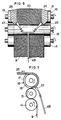
- the uppermost one 16 of the nip rollers comprises a barrel including, as best shown in Figures 2 and 3, a larger-diameter middle portion 17 and a pair of smaller-diameter end portions 18, 19 between which the middle portion 17 is disposed.
- An annular shoulder 20 is defined between the middle portion 17 and each of the end portions 18, 19 and has herein a series of holes or orifices 21 opening axially of the roller 16.
- the middle portion 17 is coupled to an air compressor (not shown) for blowing an air blast through the holes 21 axially over the smaller-diameter end portions 18, 19.
- the web 9 travels between the nip rollers 14, 15, 16 and is wrapped partly around the roller 16, only the middle portion 23 ( Figure 2) of the web along its length being nipped between the nip roller 15 and the larger-diameter middle portion 17 of the nip roller 16 and the opposite selvages or longitudinal marginal edges 24, 25 of the web 9 over-hanging the smaller-diameter end portions 18, 19, respectively, therearound.
- An air blast discharged through the holes 21 ip the shoulders 20 impinges upon the selvages 24, 25 to spread the fibers thereof transversely away from each other, whereby the selvages 24, 25 are caused to shrink longitudinally or shorten until they are brought radially inwardly into contact with the surfaces of the smaller-diameter end portions 18, 19.
- the selvages 24, 25 Upon contact with the smaller-diameter end portions 18, 19, the selvages 24, 25 are forced to travel therewith in an arcuate path in which they are prevented from being laterally spread further.
- the amount of transverse spreading of the selvages 24, 25 is automatically controlled dependent on the diametrical difference between the roller portions 17 and 18, 19.
- At least one, or preferably a pair of dimensionally stable threads 26, 27 such, for example, as those of flat yarn which are coated with hot-melt adhesive are guided around electrically heated pulleys 28, 29 disposed on the smaller-diameter end portions 18, 19 of the nip roller 16.
- the threads 26, 27 are fed around the pulleys 28, 29, the threads 26, 27 are bonded by the melted adhesive the the transversely spread selvages 24, 25 on the smaller-diameter end portions 18, 19, as best illustrated in Figure 4.
- the web 9, which is longer at the middle portion 23 than at the selvages 24, 25, is directed toward cloth guiders 31 (one set shown) which are spaced laterally from each other by a distance several times greater than the width of the middle web portion 23 as substantially unspread.
- cloth guiders 31 one set shown
- the reinforced selvages 24, 25 are gripped by the cloth guiders 31, whereupon the middle portion 23 of the web 9 is transversely spread and at the same time thereby longitudinally shrunk or shortened to an extent determined by the amount of lateral spreading.
- the amount of transverse spreading of the middle portion 23 effected by the cloth guiders 31 is made smaller than that of the selvages 24, 25.
- the remaining excessive length of the middle portion 23 of the web 9 is removed by causing the web 9 to travel around a pair of heated drums 32, 33 on which the middle portion 23 is additionally longitudinally heat-shrunk until it . has substantially the same length as that of the selvages 24, 25.
- the laterally spread and heat- treated web 11 is substantially uniform in length and reticular structure. With the width of each of the fibers in the reticular web being on the order of 1 mm or greater, each fiber tends to rise obliquely when the web is transversely spread. The greater the width of each fiber, the more the fibre undergoes such tendency. However, the fibers are held flatwise against the heated drums 32, 33 and thereby heat-set in stabilized flat arrangement.
- the web is longitudinally shortened only by several per cent or less when it is transversely spread two to three times. Additional heat shrinkage of the web, if limited to several to about 10 per cent would enhance the thermal stability rather than the lower mechanical strength thereof.
- the treated web 11, upon having left the heated drum 33, may be wound up as an end product for shipment.
- the web 11 is coated with hot-melt adhesive or emulsion adhesive contained in an adhesive container 34 by a kiss roller 35 partly immersed in the adhesive in the container 34.
- the web 11 is then caused to travel around rollers 36, 37, 38, 39 for uniform distribution and drying and cooling of the coated adhesive before being guided by guides 40 and a guide roller 41 toward a take-up reel 42.
- the web 11 is wound up as a roll 43 on the take-up reel 42.
- Each of the selvages 24, 25 including the threads 26, 27 has a basis weight which is substantially the same as or smaller than that of the middle portion 23. More specifically, it has been customary practice to reinforce paper or film with fibres having a tensile strength at break of 4-5 g/denier, which fibres are arranged warpwise and weftwise in layers so as to have a basis weight of either 20-25 g/m 2 for light reinforcement on 40-60 g/m 2 for heavy-duty reinforcement.
- a reticular web produced from a stretched film having a thickness of 20 microns and a basis weight of 20 g/m 2 before lateral spreading is transversely spread two times until the web has a basis weight of about 10 g/m 2 , which corresponds to 900 denier per 10 mm of width.
- the middle portion of the web has that basis weight
- the selvages of the web are transversely spread four times until their basis weight corresponds to 450 denier per 10 mm of width.
- each selvage including the bonded yarns has a basis weight corresponding to 850 denier per 10 mm of width which is slightly smaller than that of the middle portion of the web.
- each of the selvages is transversely spread six times and two reinforcement threads of 200 denier are bonded to each selvage.
- Each such selvage including the two threads has a basis weight equivalent to 550 denier per 10 mm of width, which is substantially half that of the middle portion of the web.
- the roll 43 is wound more tightly at the middle portion 23 than at the selvages 24, 25 so that the roll 43 will be resistant to forces tending to tumble or collapse itself and hence can be easily handled during shipment and storage for example.
- the spread web 11 when unwound is stable in dimension especially at the selvages 24, 25, which can reliably be guided or supported by suitable guides during subsequent processing.
- HDPE high-density polyethylene
- the sheet was cut by a rotary cutter to form therein 10 mm long longitudinal discrete cuts or slits in a staggered arrangement, spaced 3 mm laterally and longitudinally from each other, and then was fed into a bath of hot water at 100°C, in which the web was longitudinally stretched 8.5 times the original length to a width of 510 mm and was taken off by nip rollers onto heated drums, on which the web was dried.
- the web was then transversely spread to a small degree by the cloth guiders 13 as shown in Figures 1 and 2 to a width of 620 mm and was caused to travel around the nip rollers 14, 15, 16, the roller 16 having a middle barrel portion of 600 mm in length.
- the selvages of the web each having a width of 10 mm were transversely spread by an air blast discharged through the holes 21.
- Two HDPE parallel flat yarns of 200 denier spaced 10 mm from each other and coated with ethylene-vinyl acetate copolymer hot-melt adhesive were bonded warpwise to each of the transversely spread selvages.
- the web was transversely spread at the middle portion by the guiders 31 two times to a width of 1.2 m, and the web was caused to travel around the heated drums 32, 33 at a speed of 200 m/min, to thereby heat-shrink the middle web portion in the longitudinal direction.
- the web was then coated with hot-melt adhesive by the kiss roller 35, and the adhesive was evenly respread on the heated drums 36-38, followed by cooling on a cooling drum 39.
- the resultaht spread web which was 1250 mm wide with a basis weight of 10 g/m 2 , was wound up around the take-up reel 42 at a speed of 200 m/min.
- Example 2 Two pieces of the sheet having a width of 1.5 m obtained in Example 1 were separately given longitudinal discrete cuts and longitudinally stretched six times the original length in a hot-water bath, and then the webs were superposed on each other and additionally longitudinally stretched again to 8.5 times the original length.
- the longitudinally stretched webs as superposed were dried and thereafter processed as in Example 1 into.
- a laterally spread web product having a width of 1.25 mm and a basis weight of 20 g/m 2 , which is twice that of the product obtained in Example 1, and were then would up into a roll at a speed of 200 m/min.
- the obtained web product had a basis weight of 10 g/m 2 and a width of 2.5 m.
- a pair of nozzles 46, 47 are disposed adjacent to and directed toward the smaller-diameter portions 18, 19, respectively, of the nip roller 16.
- the nozzles 46, 47 are connected to a pipe 48 which is in turn connected to a source of compressed air (not shown) for blowing an air blast through the nozzles 46, 47 to the selvages 24, 25 of the reticular web 9.
- the nozzles 46, 47 continue to discharge the air blast toward the selvages 24, 25 for laterally spreading the latter onto the smaller-diameter roller portions 18, 19 of the nip roller 16.
- FIGS 8 and 9 illustrate still another embodiment in which a casing 50 surrounds a portion of each of the smaller-diameter portions 18, 19 of the roller 16.
- An air suction pump 51 is coupled to the casing 50 to develop air suction in the casing 50 so that the selvages 24, 25 of the reticular web 9 can be transversely spread in opposite outward directions within the casings 50, respectively.
- a rotatable brush 53 supported on a shaft 54 is disposed adjacent to each of the smaller-diameter portions 18, 19 of the nip roller 16.
- the brush 53 has a multiplicity of wires 55 projecting radially outwardly for engaging and spreading the selvages 24, 25 onto the smaller-diameter roller portions 18, 19 upon rotation of the brushes 53.
Landscapes
- Engineering & Computer Science (AREA)
- Textile Engineering (AREA)
- Nonwoven Fabrics (AREA)
Claims (16)
Applications Claiming Priority (2)
| Application Number | Priority Date | Filing Date | Title |
|---|---|---|---|
| JP55002315A JPS5810507B2 (ja) | 1980-01-12 | 1980-01-12 | 拡幅網状経ウエブ並びにその製法 |
| JP2315/80 | 1980-01-12 |
Publications (3)
| Publication Number | Publication Date |
|---|---|
| EP0032800A2 EP0032800A2 (fr) | 1981-07-29 |
| EP0032800A3 EP0032800A3 (en) | 1982-02-10 |
| EP0032800B1 true EP0032800B1 (fr) | 1984-02-22 |
Family
ID=11525895
Family Applications (1)
| Application Number | Title | Priority Date | Filing Date |
|---|---|---|---|
| EP81300118A Expired EP0032800B1 (fr) | 1980-01-12 | 1981-01-12 | Nappe en forme de filet ayant des lisières renforcées, et procédé et appareil pour la fabriquer |
Country Status (4)
| Country | Link |
|---|---|
| US (1) | US4335070A (fr) |
| EP (1) | EP0032800B1 (fr) |
| JP (1) | JPS5810507B2 (fr) |
| DE (1) | DE3162330D1 (fr) |
Families Citing this family (5)
| Publication number | Priority date | Publication date | Assignee | Title |
|---|---|---|---|---|
| US4532163A (en) * | 1983-02-25 | 1985-07-30 | Eaton Corporation | Elastomeric member |
| IE57079B1 (en) * | 1984-09-03 | 1992-04-22 | Kaysersberg Emballages Sa | Laminated web |
| US4726807A (en) * | 1986-04-10 | 1988-02-23 | Weyerhaeuser Company | Diaper with elastic margins |
| EP3375588B1 (fr) * | 2015-08-04 | 2020-11-25 | Mitsubishi Chemical Corporation | Matière plastique renforcée de fibres et son procédé de production |
| JP7326021B2 (ja) * | 2019-05-16 | 2023-08-15 | 朝日インテック株式会社 | 光照射デバイス、及び、光照射システム |
Family Cites Families (6)
| Publication number | Priority date | Publication date | Assignee | Title |
|---|---|---|---|---|
| US3416714A (en) * | 1966-07-05 | 1968-12-17 | Phillips Petroleum Co | Method of fibrillation |
| US3730821A (en) * | 1970-11-23 | 1973-05-01 | Hercules Inc | Interconnected network structure |
| DE2202828C2 (de) * | 1972-01-21 | 1973-09-27 | Vereinigte Papierwerke Schickedanz & Co, 8500 Nuernberg | Verfahren und Anlage zum kontinuierlichen elektrostatischen Spreizen von aufgespleißten Flächengebilden |
| US4116892A (en) * | 1975-03-31 | 1978-09-26 | Biax-Fiberfilm Corporation | Process for stretching incremental portions of an orientable thermoplastic substrate and product thereof |
| DE2545696A1 (de) * | 1975-10-11 | 1977-04-14 | Rotta Gmbh & Co Dr | Verfahren zum verstaerken von kanten bzw. kantenbereichen bei gewirken, geweben und vliesen |
| US4251585A (en) * | 1978-05-01 | 1981-02-17 | Biax Fiberfilm Corporation | Product and process for stretching a tubularly formed sheet of orientable thermoplastic material |
-
1980
- 1980-01-12 JP JP55002315A patent/JPS5810507B2/ja not_active Expired
-
1981
- 1981-01-07 US US06/222,972 patent/US4335070A/en not_active Expired - Lifetime
- 1981-01-12 EP EP81300118A patent/EP0032800B1/fr not_active Expired
- 1981-01-12 DE DE8181300118T patent/DE3162330D1/de not_active Expired
Also Published As
| Publication number | Publication date |
|---|---|
| DE3162330D1 (en) | 1984-03-29 |
| JPS56101967A (en) | 1981-08-14 |
| US4335070A (en) | 1982-06-15 |
| EP0032800A3 (en) | 1982-02-10 |
| EP0032800A2 (fr) | 1981-07-29 |
| JPS5810507B2 (ja) | 1983-02-25 |
Similar Documents
| Publication | Publication Date | Title |
|---|---|---|
| US2693844A (en) | Apparatus for reinforcing sheet material | |
| US3429522A (en) | Forming tube for glass fibers | |
| US3715878A (en) | Process for making chenille-type yarn | |
| US4460086A (en) | Tubular glass fiber package and method | |
| US4335070A (en) | Method of manufacturing a reticular web having reinforced selvages | |
| JPH0357203B2 (fr) | ||
| US3713190A (en) | Method for developing and converging a band of fibers or threads | |
| US3645299A (en) | Process for the production of foil ribbon fabrics and apparatus for carrying out this process | |
| US3193904A (en) | Apparatus for folding a paper strip into a yarn | |
| JPS6042301B2 (ja) | 太繊度合成繊維フイラメントの延伸方法 | |
| US5246521A (en) | Film container, teremp and method of bonding teremp to shell plate of film cartridge | |
| US3545494A (en) | Forming tube for glass fibers | |
| US3756530A (en) | Paper tube bobbin for treatment of yarn in cheese form | |
| US2847056A (en) | Method and apparatus for producing reinforced sheet material | |
| US3849847A (en) | Process for storing textile filaments in knitted form | |
| JPH07258933A (ja) | 折り重ね延伸テープヤーンの製造方法および製造装置 | |
| US3677484A (en) | Method for winding up a thin layer material having a broad width | |
| US2725323A (en) | Method for the manufacture of fabrics | |
| US4571792A (en) | Method of treating warp yarn ends in a sizing process | |
| US6610176B2 (en) | Coreless papermaker's yarn | |
| JPS5838541B2 (ja) | プラスチックフィルムからの布はく製造法 | |
| US4519195A (en) | Helical wrapping of tape | |
| US3409493A (en) | Process for twistless multifilament polyethylene terephthalate yarn | |
| JPH05297521A (ja) | 写真フイルムパトローネ用テレンプの製造方法 | |
| JP2686799B2 (ja) | リング状シームレスベルト |
Legal Events
| Date | Code | Title | Description |
|---|---|---|---|
| PUAI | Public reference made under article 153(3) epc to a published international application that has entered the european phase |
Free format text: ORIGINAL CODE: 0009012 |
|
| AK | Designated contracting states |
Designated state(s): DE FR GB |
|
| PUAL | Search report despatched |
Free format text: ORIGINAL CODE: 0009013 |
|
| AK | Designated contracting states |
Designated state(s): DE FR GB |
|
| 17P | Request for examination filed |
Effective date: 19820113 |
|
| EL | Fr: translation of claims filed | ||
| GRAA | (expected) grant |
Free format text: ORIGINAL CODE: 0009210 |
|
| AK | Designated contracting states |
Designated state(s): DE FR GB |
|
| REF | Corresponds to: |
Ref document number: 3162330 Country of ref document: DE Date of ref document: 19840329 |
|
| ET | Fr: translation filed | ||
| PLBE | No opposition filed within time limit |
Free format text: ORIGINAL CODE: 0009261 |
|
| STAA | Information on the status of an ep patent application or granted ep patent |
Free format text: STATUS: NO OPPOSITION FILED WITHIN TIME LIMIT |
|
| 26N | No opposition filed | ||
| PGFP | Annual fee paid to national office [announced via postgrant information from national office to epo] |
Ref country code: GB Payment date: 19980105 Year of fee payment: 18 |
|
| PGFP | Annual fee paid to national office [announced via postgrant information from national office to epo] |
Ref country code: DE Payment date: 19980123 Year of fee payment: 18 |
|
| PGFP | Annual fee paid to national office [announced via postgrant information from national office to epo] |
Ref country code: FR Payment date: 19980130 Year of fee payment: 18 |
|
| PG25 | Lapsed in a contracting state [announced via postgrant information from national office to epo] |
Ref country code: GB Free format text: LAPSE BECAUSE OF NON-PAYMENT OF DUE FEES Effective date: 19990112 |
|
| GBPC | Gb: european patent ceased through non-payment of renewal fee |
Effective date: 19990112 |
|
| PG25 | Lapsed in a contracting state [announced via postgrant information from national office to epo] |
Ref country code: FR Free format text: LAPSE BECAUSE OF NON-PAYMENT OF DUE FEES Effective date: 19990930 |
|
| PG25 | Lapsed in a contracting state [announced via postgrant information from national office to epo] |
Ref country code: DE Free format text: LAPSE BECAUSE OF NON-PAYMENT OF DUE FEES Effective date: 19991103 |
|
| REG | Reference to a national code |
Ref country code: FR Ref legal event code: ST |