EP0033161A1 - Procédé et circuit de commande pour surveiller la température d'un moteur électrique - Google Patents
Procédé et circuit de commande pour surveiller la température d'un moteur électrique Download PDFInfo
- Publication number
- EP0033161A1 EP0033161A1 EP81100617A EP81100617A EP0033161A1 EP 0033161 A1 EP0033161 A1 EP 0033161A1 EP 81100617 A EP81100617 A EP 81100617A EP 81100617 A EP81100617 A EP 81100617A EP 0033161 A1 EP0033161 A1 EP 0033161A1
- Authority
- EP
- European Patent Office
- Prior art keywords
- motor
- speed
- microcomputer
- condition
- power
- Prior art date
- Legal status (The legal status is an assumption and is not a legal conclusion. Google has not performed a legal analysis and makes no representation as to the accuracy of the status listed.)
- Granted
Links
- 238000000034 method Methods 0.000 title claims 7
- 238000012544 monitoring process Methods 0.000 title claims 7
- 238000010438 heat treatment Methods 0.000 claims description 34
- 238000005259 measurement Methods 0.000 claims description 7
- 230000001105 regulatory effect Effects 0.000 claims description 7
- 230000008859 change Effects 0.000 claims description 6
- 239000011159 matrix material Substances 0.000 claims description 6
- 238000010304 firing Methods 0.000 claims description 5
- 230000006870 function Effects 0.000 claims description 5
- 239000004065 semiconductor Substances 0.000 claims description 4
- 230000001276 controlling effect Effects 0.000 claims description 2
- 230000002401 inhibitory effect Effects 0.000 claims 2
- 230000011664 signaling Effects 0.000 claims 1
- 230000005355 Hall effect Effects 0.000 description 8
- 238000001816 cooling Methods 0.000 description 8
- 230000000694 effects Effects 0.000 description 8
- 239000003990 capacitor Substances 0.000 description 7
- 238000010586 diagram Methods 0.000 description 5
- 230000009471 action Effects 0.000 description 2
- 230000002457 bidirectional effect Effects 0.000 description 1
- 230000000903 blocking effect Effects 0.000 description 1
- 230000000295 complement effect Effects 0.000 description 1
- 239000013078 crystal Substances 0.000 description 1
- 230000003247 decreasing effect Effects 0.000 description 1
- 238000001514 detection method Methods 0.000 description 1
- 238000006073 displacement reaction Methods 0.000 description 1
- 239000000463 material Substances 0.000 description 1
- 230000008520 organization Effects 0.000 description 1
- 230000002093 peripheral effect Effects 0.000 description 1
- 230000001681 protective effect Effects 0.000 description 1
- 230000009467 reduction Effects 0.000 description 1
- 230000004044 response Effects 0.000 description 1
- 230000001629 suppression Effects 0.000 description 1
- 230000007704 transition Effects 0.000 description 1
Images


Classifications
-
- H—ELECTRICITY
- H02—GENERATION; CONVERSION OR DISTRIBUTION OF ELECTRIC POWER
- H02P—CONTROL OR REGULATION OF ELECTRIC MOTORS, ELECTRIC GENERATORS OR DYNAMO-ELECTRIC CONVERTERS; CONTROLLING TRANSFORMERS, REACTORS OR CHOKE COILS
- H02P25/00—Arrangements or methods for the control of AC motors characterised by the kind of AC motor or by structural details
- H02P25/02—Arrangements or methods for the control of AC motors characterised by the kind of AC motor or by structural details characterised by the kind of motor
- H02P25/10—Commutator motors, e.g. repulsion motors
- H02P25/14—Universal motors
- H02P25/145—Universal motors whereby the speed is regulated by measuring the motor speed and comparing it with a given physical value, speed feedback
-
- H—ELECTRICITY
- H02—GENERATION; CONVERSION OR DISTRIBUTION OF ELECTRIC POWER
- H02H—EMERGENCY PROTECTIVE CIRCUIT ARRANGEMENTS
- H02H6/00—Emergency protective circuit arrangements responsive to undesired changes from normal non-electric working conditions using simulators of the apparatus being protected, e.g. using thermal images
- H02H6/005—Emergency protective circuit arrangements responsive to undesired changes from normal non-electric working conditions using simulators of the apparatus being protected, e.g. using thermal images using digital thermal images
-
- H—ELECTRICITY
- H02—GENERATION; CONVERSION OR DISTRIBUTION OF ELECTRIC POWER
- H02H—EMERGENCY PROTECTIVE CIRCUIT ARRANGEMENTS
- H02H7/00—Emergency protective circuit arrangements specially adapted for specific types of electric machines or apparatus or for sectionalised protection of cable or line systems, and effecting automatic switching in the event of an undesired change from normal working conditions
- H02H7/08—Emergency protective circuit arrangements specially adapted for specific types of electric machines or apparatus or for sectionalised protection of cable or line systems, and effecting automatic switching in the event of an undesired change from normal working conditions for dynamo-electric motors
- H02H7/085—Emergency protective circuit arrangements specially adapted for specific types of electric machines or apparatus or for sectionalised protection of cable or line systems, and effecting automatic switching in the event of an undesired change from normal working conditions for dynamo-electric motors against excessive load
- H02H7/0854—Emergency protective circuit arrangements specially adapted for specific types of electric machines or apparatus or for sectionalised protection of cable or line systems, and effecting automatic switching in the event of an undesired change from normal working conditions for dynamo-electric motors against excessive load responsive to rate of change of current, couple or speed, e.g. anti-kickback protection
-
- H—ELECTRICITY
- H02—GENERATION; CONVERSION OR DISTRIBUTION OF ELECTRIC POWER
- H02P—CONTROL OR REGULATION OF ELECTRIC MOTORS, ELECTRIC GENERATORS OR DYNAMO-ELECTRIC CONVERTERS; CONTROLLING TRANSFORMERS, REACTORS OR CHOKE COILS
- H02P23/00—Arrangements or methods for the control of AC motors characterised by a control method other than vector control
- H02P23/0077—Characterised by the use of a particular software algorithm
Definitions
- the subject invention generally relates to electric motor control systems, and more particularly to a digital control system for electric motors in power tools or the like. More specifically, the present invention relates to such a control system employing a microcomputer speed regulator for the direct digital firing of thyristors placed between an AC source and the motor of such well known electric motor driven tools as universal motor or AC motor driven drills, saws or the like.
- a digital control system for electric motors including a microcomputer controlled speed regulator for maintaining a preselected speed of the electric motor substantially constant between no load and full load operation of the motor.
- Speed selecting means are connected as an input to the microcomputer for inputting the preselected speed.
- the speed selecting means may be any suitable type such as a rotary switch.
- the actual speed of the motor is calculated by the microcomputer from the speed signal information derived from a speed sensor device operatively coupled to the motor.
- the microcomputer is programmed to control the speed ofthe motor in accordance with the preselected speed value by controlling the conduction angle of a power semiconductor control device which controls the application of power to the motor.
- the microcomputer also utilizes the speed signal information from the speed sensor to provide anti- kickback protection for the power tool. More particularly, the microcomputer is programmed to recognize when the rotational speed of the motor is decelerating and to detect when the rate of deceleration exceeds a predetermined rate. In response to the detection of such an occurrence, the microcomputer will automatically cut power to the motor.
- the overload calculation utilizes a numerical integrator, which in the preferred embodiment comprises a storage register whose contents are periodically updated by adding to or subtracting from the current value a "heating value" which is determined according to the conduction angle (voltage) and measured speed of the motor.
- the "heating values" assigned to each of the various operating ranges of the motor are empirically determined and stored in matrix form in the microcomputer. Positive “heating values” correspond to a net heat increase and negative values correspond to a net heat loss.
- FIG. 1 and 2 show side and top views, respectively, of the hand-held power drill.
- This tool comprises a main body portion 10 and a centrally disposed handly portion 12.
- the main body portion houses the electric motor and gear reduction unit that drives the drill chuck 14.
- a cooling fan (not shown) is affixed to the output shaft of the motor to facilitate cooling of the tool.
- the main body portion 10 houses the microcomputer in a compartment 16 in the top of the main body portion, and adjacent thereto is the selector dial 18 of the rotary speed selector switch.
- the selector dial 18 is only partially exposed, the major portion of the dial being within the main body portion of the power drill.
- the main body portion 10 houses a signal device 20 which outputs a pulse responsive to motor rotation to permit measurement of the speed of the motor.
- the signal device 20 comprises a plastic member 22 attached to the shaft 24 of the motor.
- the plastic member 22 rotates with the motor shaft within a protective cup-shaped member 26 and has embedded in a peripheral edge thereof a permanent magnet 28.
- the cup-shaped member 26 supports a magnetic field detecting device 30, such as a Hall effect sensor, in proximity to the path of the permanent magnet 28. As the magnet 28 passes close to the Hall effect sensor 30, an electric pulse is generated by the sensor so that one pulse is generated for each revolution of the electric motor.
- the microcomputer program as set forth hereinafter will measure the speed of the motor by measuring the time between these electrical pulses.
- the handle portion 12 is provided with a trigger 32 which is used to actuate an on-off switch.
- a compartment 34 in the handle portion 12 is used to house the power supply and control circuits.
- the AC line cord enters the bottom of the handle portion and connects directly with the power supply and control circuits.
- microcomputer which maybe any one of a number of commercially available microcomputers. These are integrated circuit devices containing all of the functions required in a digital computing system. In the embodiment which will be described with reference to Figure 4, a 3870 microcomputer (available from Mostek, Motorola or Fairchild) is used.
- the instruction register 36 receives the operation code of the instruction to be executed from the program read only memory (ROM) 38 via the data bus 40.
- the main control logic 42 decodes the instruction and provides the necessary control and gating signals to all microcomputer circuit elements in order to execute the instruction.
- Associated with the read only memory 38 are four 11 bit registers indicated by a single block 44 in the figure. These are the program counter, the stack register, the data counter and the auxiliary data counter.
- the program counter is used to address instructions or immediate operands.
- the stack register is used to save the contents of the program counter during an interrupt or subroutine call. In other words, the stack register contains the return address at which processing is to resume upon completion of the subroutine or the interrupt routine.
- the data counter is used to address data tables in the read only memory 38.
- This register is auto-incrementing. Of the two data counters, only the first can access the read only memory although an instruction allows the data counter and the auxiliary data counter to be interchanged.
- an 11 bit adder/incrementer 46 Associated with the address registers is an 11 bit adder/incrementer 46. This logic element is used to increment the program counter or the data counter when required and is also used to add displacements to the program counter on relative branches or to add the data bus contents to the data counter.
- the microcomputer program and data constants are stored in the read only memory 38. When a read only memory access is required, the appropriate address register, i.e., the program counter or the data counter, is gated onto the read only memory address bus 48 and the read only memory output is gated onto the main data bus 40.
- the scratchpad registers 50 may be used as a general purpose random access memory (RAM).
- the indirect scratchpad address register 52 is a 6 bit register used to address the sixty-four scratchpad registers 50, and all sixty-four of these registers may be accessed using the indirect scratchpad address register.
- the lower 12 registers may also be directly addressed.
- the indirect scratchpad a address register may be visualized as holding two octal digits. The significance of this is that a number of instructions increment or decrement the least significant 3 bits or the most significant 3 bits when referencing scratchpad bytes via the indirect scratchpad address register.
- the arithmetic and logic unit (ALU) 54 After receiving commands from the main control logic 42 the arithmetic and logic unit (ALU) 54 performs the required arithmetic, logic or input/output operations using the data presented on the two input buses 56 and 58 and provides the result on the result bus 60.
- the arithmetic operations that can be performed in the arithmetic and logic unit are add, decimal adjust, add with carry, decrement, and increment.
- the logic operations that can be performed are AND, OR,Exclusive OR, l's complement, shift right, and shift left.
- the arithmetic and logic unit 54 also provides four signals representing the status of the result.
- the status register 62 stores signals or flags and represent carry, overflow, sign and zero condition of the result of the operation.
- the status register also holds a fifth status flag which is the interrupt control bit that can be used to enable or disable interrupt requests to the microcomputer.
- the accumulator 64 is the principal register for data manipulation with the microcomputer. The accumulator 64 serves as one input to the arithmetic and logic unit 54 for arithmetic and logical operations. No interrupts are acknowledged if the interrupt control bit is false. If the interrupt control bit is true and the program has enabled either the. external interrupt or the timer interrupt or both, an interrupt when requested will be acknowledged and processed.
- the timer 78 is an 8 bit binary down counter which is software programmable to operate in one of three modes: the interval timer mode, the pulse width measurement mode, or the event counter mode.
- the timer 78 includes a programmable prescaler and an 8 bit modulo-N counter.
- the desired timer mode, prescale value, starting and stopping the timer, active level ' of the external interrupt pin, and local enabling and disabling of interrupt are selected by outputting the proper bit configuration from the accumulator 64 to the interrupt control port 76.
- the rate at which the timer 78 is clocked in the interval timer mode is determined by the frequency of an internal clock and by the division value selected for the prescaler.
- the prescaler is used to clock the 8 bit down counter in the interval timer mode.
- the modulo-N counter is a buffer whose function is to save the value which was most recently outputted by the timer.
- the external interrupt pin With the timer 78 in the interval timer mode, the external interrupt pin is available for non-timer related interrupts.
- an external interrupt request latch When enabled, an external interrupt request latch is set when there is a transition from the inactive level to the active level. If there is both a timer interrupt request and an external interrupt request, the timer interrupt is handled first.
- the reset input goes low and initialization occurs.
- the program counter and the interrupt control bit of the status register are cleared.
- Ports 72, 74, and 76 and the timer 78 are loaded with 0's.
- a power plug 80 is adapted to be plugged into an AC outlet and is provided with powerlines 82 and 84.
- Power line 84 is connected to the cathode of SCR 86 and to the anode of SCR 88.
- the anode of SCR 86 is connected in common with the cathode of SCR88 to motor 90.
- Motor 90 is a universal electric motor comprising a field 92 connected in series with an armature 94 and having a switching noise suppression capacitor 96 connected in parallel with the series connection of field 92 and armature 94.
- the common junction of armature 94 and capacitor 96 is connected to powerline 82.
- a gate control circuit 98 supplies gating pulses to SCR 86, while a gate control circuit 100 supplies gating pulses to the gate of SCR88.
- Gate control circuits 98 and 100 are identical and, therefore, only the details of gate control circuit 98 will be described.
- This circuit comprises an opto-coupler.
- the opto-coupler package includes a light emitting diode (LED) 102 having its anode connected through resistor 104 to a source of regulated positive voltage +V.
- LED light emitting diode
- SCR 106 with a photosensitive gate having its anode connected through resistor 108 to the anode of SCR 86 and its cathode connected directly to the gate electrode of SCR 86.
- SCR 106 The gate and cathode of SCR 106 are connected together by resistor 110 to provide a bias level to the gate of that SCR.
- SCR 106 conducts to provide a gating signal to SCR 86 causing that SCR to conduct supplying current to motor 90.
- SCR 88 is caused to conduct to supply current to motor 90 in alternate half cycles of the AC power by gate control circuit 100.
- the DC power supply which develops the supply voltage for the various circuits used in Figure 4 comprises a resistor 112, a rectifier diode 114 and a filter capacitor 116 connected in series from powerline 82 to powerline 84.
- a Zener diode 118 is connected in parallel with capacitor 116, and a series voltage regulator 120 is connected to the common junction of diode 114 and capacitor 116 and provides a regulated output at terminal 122 indicated as +V.
- Voltage regulator 120 may be, for example, a type MC78M05C regulator manufactured by Motorola Semiconductor Products, Inc.
- a further filter capacitor 124 is connected across the output of regulator 120.
- the heart of the system shown in Figure 4 is a microcomputer 126 which was described with reference to Figure 3.
- This computer. is fabricated as an integrated circuit having a total of 40 pin connectors.
- Pins 3 c -6 c and 16 c -19 c comprise the 8-bit port 68
- pins 34 c -37 c and 22 c -25 c comprise the 8-bit port 70
- pins 8 c -15 c comprise the 8-bit port 72
- pins 26 c -33 c comprise the 8-bit port 74.
- Pins 1 c and 2 c are connected to an external crystal 128 which supplies a timing reference.
- the regulated +V from the power supply terminal 122 is connected to pin 40_while pin 20 c is connected to system common.
- rotary switch 128 a which is operated by selector dial 18 shown in Figures 1 and 2 is connected to pins 34 c -37 c of port 70.
- Pin 32 c of port 74 is connected to the cathode of the LED in switch control circuit 100, and pin 33 c of port 74 is connected to the cathode of LED 102.
- a Hall effect sensor 30 is connected to the interrupt input at pin 38 c of microcomputer 126.
- a pull-up resistor 134 is connected between pin 38 c and the regulated positive voltage +V, and the Hall effect sensor 30 is connected between the regulated positive voltage +V and the system common.
- a Hall effect sensor is a commercially available item manufactured by Sprague with the designation UGN 3013.
- the Hall effect sensor 30 produces an output when magnet 28 shown in Figure 1 passes in proximity to the Hall effect sensor 30.
- an external interrupt is acknowledged.
- the external interrupt service routine stops the internal timer, records its value and restarts the timer. This measures the time-elapsed since the previous external interrupt, which is the time during which the shaft completed one revolution.
- AC powerline zero crossing information is generated by a transistor 136 having its emitter connected to system common and its collector connected to pin 3 c of microcomputer 126.
- the base of transistor 136 is connected via resistor 138 to powerline 82.
- Power on reset is provided to reset pin 39 c by the circuit comprising resistors. 140 and 142, Zener diode 144 and diode 146.
- Resistor 140 is connected between the junction of diode 114 and capacitor 116 and the cathode of Zener diode 144.
- Resistor 142 is connected between the anode of Zener diode 144 and powerline 84.
- the cathode of diode 146 is connected to terminal 122 while the anode of diode 146 is connected to the junction of Zener diode 144 and resistor 142 and also to reset pin 39.
- the effect of this circuit is to apply a low value to the reset pin when power is first supplied to the powerlines 82 and 84. After a short period, a high value is clamped to the reset pin 3 0 c .
- the power cord In order to operate the hand-held power drill, the power cord must be plugged into a source of AC voltage by means of plug 80, a speed selected by means of rotary switch 128 a, and switch 146 a must be closed. Switch 146 a is actuated by the trigger 32 shown in Figure 1.
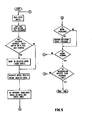
- the simplified flow diagram of the microcomputer main program is shown in Figure 5. Assuming, first of all, that the power cord of the power tool has been plugged into an AC outlet, a speed has been selected and the trigger is pulled on, the first step in the flow diagram is to read the speed switch 128 a. The microcomputer then determines whether the operator has changed the speed or the motor is just starting. If either of these conditions is determined to exist, then the microcomputer ramps the motor speed to the selected speed. This is accomplished with a slow start routine, but basically what microcomputer 126 does is to incrementally increase the length of time per AC half cycle during which current is supplied to the motor until the selected speed has been reached.
- This routine is basically a digital feedback speed control of the electric motor 90 which compares the actual speed with the selected speed to generate an error quantity which is used to alter the time per AC half cycle during which current is supplied to the motor via SCRs 86 and 88.
- the actual speed is computed when the magnet 28 passes by the Hall effect sensor 30 which creates a pulse at the external interrupt input.
- the external interrupt is acknowledged and elapsed time is measured as . described hereinbefore, this time being inversely proportional to the speed of motor 90
- the overload calculation is performed. This calculation determines if an overload condition exists based on the measured speed of the motor 90.. and the firing angles of the SCRs 86 and 88. If an overload condition is detected the motor speed is decreased to a very low and poorly controlled speed until a normal operating temperature is reached. This serves as a warning indication to the operator.
- the cooling fan is driven directly off the armature of the motor. Accordingly, the cooling effect contributed by the fan can be determined from the measured speed of the motor. In addition, the current drawn by the motor can be determined from the speed of the motor and the conduction angle of the SCRs 86 and 88. Thus, it can be seen that the information necessary to infer the operating temperature of the motor is already available to the microcomputer.
- a motor can safely be operated at current levels which will ultimately cause an overload condition as long as the period of operation at such levels is limited accordingly.
- the period of safe operation will vary inversely with the magnitude of the current drawn by the motor and directly with the speed of the motor, where a cooling fan is driven off the motor armature.
- the control circuit accomplishes this by utilizing what in effect is a numerical integrator. In particular, sixty times each second an empirically determined "heating value" is added to, or subtracted from, the contents of a 16-bit register. The selection of the particular "heating value” is based upon the operating speed of the motor as measured by the speed sensor 30 and the conduction angle of SCRs 86 and 88. If the total in the register ever exceeds a predetermined limit, an overload condition is signalled. Normal operation is resumed when the total in the register drops below a second lower predetermined limit. A minor negative heating effect is assumed when the motor is not running.
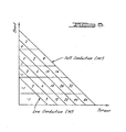
- FIG. 6 the speed vs. torque curves for the motor at various conduction angles are shown.
- the uppermost diagonal line represents full conduction (180 0 )while the lowermost diagonal line represents a low conduction angle (70°).
- the area under the curves is divided further into five speed ranges, thereby creating a matrix.
- Each region in the matrix is assigned a "heating value", which is either a positive value or a negative value depending upon whether the motor experiences a net increase or decrease in temperature when operated in that region.
- the assigned heating values in the matrix take into. account not only the degree of heat generated by the motor, but also the cooling effect caused by the airflow from the fan coupled to the motor armature.
- the magnitude of the number assigned to each region is determined empirically based upon the following three factors:
- the matrix of heating values shown in Figure 6 is stored in the microcomputer 126. Sixty times each second, the microcomputer is programmed to "look-up" the appropriate heating value, based upon the present conduction angle of the SCRs 86 and 88 and the measured speed of the motor, and add (subtract) the value to the contents of a 16-bit register. In the preferred embodiment, an overload condition is signalled whenever the contents of the register equal the binary equivalent of 36,096. Resumption of normal operation occurs when the contents of the register drop below the binary equivalent of 18,175.
- the next operation performed by the microcomputer is to calculate the change in successive speed readings to determine if the motor is slowing. If not, the program returns to the step of reading the speed switch and continues from there. If on the other hand it is determined that the motor is slowing, then it is necessary to determine if an impending kickback condition exists.
- the motor speed is inferred from time measurements, and so a deceleration will be found to exist when the most recent time measurement (NSR) is greater than the next most recent time measurement (OSR). The difference between these readings is a measure of the deceleration of the motor. It has been determined that when a kickback condition exists, the deceleration of the tool and hence the motor is quite large.
- This limit is a function of selected speed, as for example, a 20% change in speed -within a 8.3 msec. period.
- the power tool is stopped. As previously explained, the microcomputer accomplishes this by ceasing to provide gate pulses to gate control circuits 98 and 100 thereby effectively blocking power to the motor 90. If on.the other hand it is determined that a kickback condition does not exist, e.g., the difference between NSR and OSR is less than the kickback limit, then the program returns to the step of reading the speed switch and continues from there.
Landscapes
- Engineering & Computer Science (AREA)
- Power Engineering (AREA)
- Control Of Ac Motors In General (AREA)
- Control Of Electric Motors In General (AREA)
- Protection Of Generators And Motors (AREA)
- Motor And Converter Starters (AREA)
Priority Applications (1)
| Application Number | Priority Date | Filing Date | Title |
|---|---|---|---|
| AT81100617T ATE12862T1 (de) | 1980-01-28 | 1981-01-28 | Verfahren und steuerung zur temperaturueberwachung eines elektrischen motors. |
Applications Claiming Priority (2)
| Application Number | Priority Date | Filing Date | Title |
|---|---|---|---|
| US11625880A | 1980-01-28 | 1980-01-28 | |
| US116258 | 2002-04-04 |
Publications (2)
| Publication Number | Publication Date |
|---|---|
| EP0033161A1 true EP0033161A1 (fr) | 1981-08-05 |
| EP0033161B1 EP0033161B1 (fr) | 1985-04-17 |
Family
ID=22366126
Family Applications (1)
| Application Number | Title | Priority Date | Filing Date |
|---|---|---|---|
| EP81100617A Expired EP0033161B1 (fr) | 1980-01-28 | 1981-01-28 | Procédé et circuit de commande pour surveiller la température d'un moteur électrique |
Country Status (3)
| Country | Link |
|---|---|
| EP (1) | EP0033161B1 (fr) |
| AT (1) | ATE12862T1 (fr) |
| DE (1) | DE3169934D1 (fr) |
Cited By (15)
| Publication number | Priority date | Publication date | Assignee | Title |
|---|---|---|---|---|
| EP0048261A4 (fr) * | 1980-03-24 | 1982-07-19 | Black & Decker Inc | Outil electrique commande par micro-ordinateur. |
| EP0071307A3 (en) * | 1981-07-31 | 1983-03-30 | Philips Electronic And Associated Industries Limited | Drum speed control system for a washing and/or spin drying machine |
| EP0086114A1 (fr) * | 1982-02-10 | 1983-08-17 | Hitachi Koki Co., Ltd. | Outil électrique avec circuit de régulation de vitesse |
| FR2526243A1 (fr) * | 1982-04-28 | 1983-11-04 | Black & Decker Inc | Montage destine a limiter le couple de rotation de moteurs universels |
| FR2548476A1 (fr) * | 1983-06-30 | 1985-01-04 | Singer Co | Procede de protection contre les surcharges dans un dispositif de commande de moteur |
| FR2564998A1 (fr) * | 1984-05-22 | 1985-11-29 | Carpano & Pons | Dispositif de regulation de vitesse |
| FR2570845A1 (fr) * | 1984-09-24 | 1986-03-28 | Black & Decker Inc | Procede de detection de surcharge et d'avertissement pour moteurs electriques dans les outils electriques et analogues |
| WO1989002672A1 (fr) * | 1987-09-18 | 1989-03-23 | Eastman Kodak Company | Appareil d'utilisation d'une alimentation en courant alternatif pour entrainer de maniere bidirectionnelle un moteur a courant continu |
| EP0332568A1 (fr) * | 1988-03-08 | 1989-09-13 | Siemens Aktiengesellschaft | Procédé de travail et circuit de commande pour surveiller le démarrage de moteurs électriques à haute tension avec démarrage asynchrone |
| GB2204152B (en) * | 1987-03-13 | 1991-05-22 | Truetzschler Gmbh & Co Kg | Control of the carding process in a carding machine |
| EP0673109A1 (fr) * | 1994-03-10 | 1995-09-20 | C.M.L. COSTRUZIONI MECCANICHE LIRI S.r.l. | Moteur électrique pour une machine-outils portable |
| US8398457B2 (en) | 2008-08-20 | 2013-03-19 | Black & Decker Inc. | Multi-sander |
| EP2324961A3 (fr) * | 2009-11-19 | 2013-09-18 | Makita Corporation | Outil portable |
| US9421682B2 (en) | 2011-07-18 | 2016-08-23 | Black & Decker Inc. | Multi-head power tool with reverse lock-out capability |
| US9956677B2 (en) | 2013-05-08 | 2018-05-01 | Black & Decker Inc. | Power tool with interchangeable power heads |
Citations (1)
| Publication number | Priority date | Publication date | Assignee | Title |
|---|---|---|---|---|
| DE2549850A1 (de) * | 1975-11-06 | 1977-05-12 | Siemens Ag | Thermische ueberlastschutzeinrichtung fuer elektrische maschinen |
Family Cites Families (1)
| Publication number | Priority date | Publication date | Assignee | Title |
|---|---|---|---|---|
| DE2310103C3 (de) * | 1973-03-01 | 1987-07-09 | Licentia Patent-Verwaltungs-Gmbh, 6000 Frankfurt | Elektronischer Überstromauslöser |
-
1981
- 1981-01-28 AT AT81100617T patent/ATE12862T1/de not_active IP Right Cessation
- 1981-01-28 DE DE8181100617T patent/DE3169934D1/de not_active Expired
- 1981-01-28 EP EP81100617A patent/EP0033161B1/fr not_active Expired
Patent Citations (1)
| Publication number | Priority date | Publication date | Assignee | Title |
|---|---|---|---|---|
| DE2549850A1 (de) * | 1975-11-06 | 1977-05-12 | Siemens Ag | Thermische ueberlastschutzeinrichtung fuer elektrische maschinen |
Non-Patent Citations (3)
| Title |
|---|
| CONTROL AND INSTRUMENTATION, Vol. 11, No. 7, July/August 1979, pages 29-31 London, G.B. P. NOBLE: "A multiprocessor system provides new approach to motor RPM control" *page 29, middle column, line 17 - page 31, right-hand column, line 18; figures on pages 29, 31 * * |
| ELECTRONICS, Vol. 52, No. 2, September 1979, pages 140-144 New York, U.S.A. T. SLADE: "Microcomputer-based control smoothes universal motor performance" * page 140, line 1 - page 144, left-hand column, line 27; figures 1-5 * * |
| IECI '78 PROCEEDINGS - INDUSTRIAL APPLICATIONS OF MICROPROCESSORS, 20th-20nd March 1978, pages 216-222 New York, U.S.A. K. KAMIYAMA et al.: "Microprocessor-controlled fast-response speed regulator for thyristorized reversible regenerative DCM drives" * page 219, right-hand column, line 12 - 220, right-hand column, line 36; line 36; figures 2, 4, 5 * * |
Cited By (21)
| Publication number | Priority date | Publication date | Assignee | Title |
|---|---|---|---|---|
| EP0048261A4 (fr) * | 1980-03-24 | 1982-07-19 | Black & Decker Inc | Outil electrique commande par micro-ordinateur. |
| EP0071307A3 (en) * | 1981-07-31 | 1983-03-30 | Philips Electronic And Associated Industries Limited | Drum speed control system for a washing and/or spin drying machine |
| EP0086114A1 (fr) * | 1982-02-10 | 1983-08-17 | Hitachi Koki Co., Ltd. | Outil électrique avec circuit de régulation de vitesse |
| FR2526243A1 (fr) * | 1982-04-28 | 1983-11-04 | Black & Decker Inc | Montage destine a limiter le couple de rotation de moteurs universels |
| FR2548476A1 (fr) * | 1983-06-30 | 1985-01-04 | Singer Co | Procede de protection contre les surcharges dans un dispositif de commande de moteur |
| FR2564998A1 (fr) * | 1984-05-22 | 1985-11-29 | Carpano & Pons | Dispositif de regulation de vitesse |
| FR2570845A1 (fr) * | 1984-09-24 | 1986-03-28 | Black & Decker Inc | Procede de detection de surcharge et d'avertissement pour moteurs electriques dans les outils electriques et analogues |
| GB2204152B (en) * | 1987-03-13 | 1991-05-22 | Truetzschler Gmbh & Co Kg | Control of the carding process in a carding machine |
| WO1989002672A1 (fr) * | 1987-09-18 | 1989-03-23 | Eastman Kodak Company | Appareil d'utilisation d'une alimentation en courant alternatif pour entrainer de maniere bidirectionnelle un moteur a courant continu |
| EP0332568A1 (fr) * | 1988-03-08 | 1989-09-13 | Siemens Aktiengesellschaft | Procédé de travail et circuit de commande pour surveiller le démarrage de moteurs électriques à haute tension avec démarrage asynchrone |
| EP0673109A1 (fr) * | 1994-03-10 | 1995-09-20 | C.M.L. COSTRUZIONI MECCANICHE LIRI S.r.l. | Moteur électrique pour une machine-outils portable |
| US5594306A (en) * | 1994-03-10 | 1997-01-14 | C.M.L. Costruzioni Meccaniche Liri S.R.L. | Electric motor for portable machine tools |
| US8398457B2 (en) | 2008-08-20 | 2013-03-19 | Black & Decker Inc. | Multi-sander |
| US8613644B2 (en) | 2008-08-20 | 2013-12-24 | Black & Decker Inc. | Multi-sander |
| US8821220B2 (en) | 2008-08-20 | 2014-09-02 | Black & Decker Inc. | Power tool with interchangeable tool head |
| US9724799B2 (en) | 2008-08-20 | 2017-08-08 | Black & Decker Inc. | Power tool with interchangeable tool head |
| US10906155B2 (en) | 2008-08-20 | 2021-02-02 | Black & Decker Inc. | Power tool with interchangeable tool head |
| EP2324961A3 (fr) * | 2009-11-19 | 2013-09-18 | Makita Corporation | Outil portable |
| US9421682B2 (en) | 2011-07-18 | 2016-08-23 | Black & Decker Inc. | Multi-head power tool with reverse lock-out capability |
| US9956677B2 (en) | 2013-05-08 | 2018-05-01 | Black & Decker Inc. | Power tool with interchangeable power heads |
| US10661428B2 (en) | 2013-05-08 | 2020-05-26 | Black & Decker Inc. | Power tool with interchangeable tool heads |
Also Published As
| Publication number | Publication date |
|---|---|
| EP0033161B1 (fr) | 1985-04-17 |
| ATE12862T1 (de) | 1985-05-15 |
| DE3169934D1 (en) | 1985-05-23 |
Similar Documents
| Publication | Publication Date | Title |
|---|---|---|
| US4307325A (en) | Digital control system for electric motors in power tools and the like | |
| EP0033161A1 (fr) | Procédé et circuit de commande pour surveiller la température d'un moteur électrique | |
| US4628233A (en) | Microprocessor based motor control | |
| US4249117A (en) | Anti-kickback power tool control | |
| USRE33379E (en) | Microprocessor based motor control | |
| US4550277A (en) | Overload detection and warning system for electric motors in power tools and the like | |
| US7551411B2 (en) | Control and protection methodologies for a motor control module | |
| US20030234630A1 (en) | Fan speed control system | |
| US4267914A (en) | Anti-kickback power tool control | |
| US6182232B1 (en) | Power and thermal management based on a power supply output | |
| JPH07178678A (ja) | ドリル・ドライバとその制御方法 | |
| US5017846A (en) | Stall protection circuit for an electronically commutated motor | |
| EP0496534A2 (fr) | Ordinateur personnel à piles | |
| EP3391491B1 (fr) | Détection de surcharge dans un outil électrique | |
| KR920018555A (ko) | 전동기용 보호장치 | |
| JP2852716B2 (ja) | キックバック状態検出方法及び該方法により制御される電動工具 | |
| US5341454A (en) | DC motor control in electronic sewing machine | |
| JPS6244822A (ja) | 停電処理方式 | |
| KR910003376B1 (ko) | 전자식 금전 등록기의 정전 처리방법 | |
| JPS592530U (ja) | ゴム等加工機の制御装置 | |
| JPS60141181A (ja) | モ−タの速度制御装置 | |
| JPS63155238A (ja) | プログラム監視方式 | |
| JPH01164228A (ja) | 電流制限カウンタ使用のトランジスタ保護装置 | |
| JP2000295762A (ja) | モータ過負荷保護装置 |
Legal Events
| Date | Code | Title | Description |
|---|---|---|---|
| PUAI | Public reference made under article 153(3) epc to a published international application that has entered the european phase |
Free format text: ORIGINAL CODE: 0009012 |
|
| AK | Designated contracting states |
Designated state(s): AT BE CH DE FR GB IT LU NL SE |
|
| 17P | Request for examination filed |
Effective date: 19811210 |
|
| ITF | It: translation for a ep patent filed | ||
| GRAA | (expected) grant |
Free format text: ORIGINAL CODE: 0009210 |
|
| AK | Designated contracting states |
Designated state(s): AT BE CH DE FR GB IT LI LU NL SE |
|
| REF | Corresponds to: |
Ref document number: 12862 Country of ref document: AT Date of ref document: 19850515 Kind code of ref document: T |
|
| REF | Corresponds to: |
Ref document number: 3169934 Country of ref document: DE Date of ref document: 19850523 |
|
| ET | Fr: translation filed | ||
| PG25 | Lapsed in a contracting state [announced via postgrant information from national office to epo] |
Ref country code: LU Free format text: LAPSE BECAUSE OF NON-PAYMENT OF DUE FEES Effective date: 19860131 |
|
| PLBE | No opposition filed within time limit |
Free format text: ORIGINAL CODE: 0009261 |
|
| STAA | Information on the status of an ep patent application or granted ep patent |
Free format text: STATUS: NO OPPOSITION FILED WITHIN TIME LIMIT |
|
| PGFP | Annual fee paid to national office [announced via postgrant information from national office to epo] |
Ref country code: LU Payment date: 19860404 Year of fee payment: 6 |
|
| 26N | No opposition filed | ||
| PGFP | Annual fee paid to national office [announced via postgrant information from national office to epo] |
Ref country code: AT Payment date: 19881228 Year of fee payment: 9 |
|
| PGFP | Annual fee paid to national office [announced via postgrant information from national office to epo] |
Ref country code: SE Payment date: 19890131 Year of fee payment: 9 Ref country code: NL Payment date: 19890131 Year of fee payment: 12 |
|
| PGFP | Annual fee paid to national office [announced via postgrant information from national office to epo] |
Ref country code: BE Payment date: 19890213 Year of fee payment: 9 |
|
| PG25 | Lapsed in a contracting state [announced via postgrant information from national office to epo] |
Ref country code: AT Effective date: 19900128 |
|
| PG25 | Lapsed in a contracting state [announced via postgrant information from national office to epo] |
Ref country code: SE Effective date: 19900129 |
|
| PG25 | Lapsed in a contracting state [announced via postgrant information from national office to epo] |
Ref country code: BE Effective date: 19900131 |
|
| BERE | Be: lapsed |
Owner name: BLACK & DECKER INC. Effective date: 19900131 |
|
| ITTA | It: last paid annual fee | ||
| PG25 | Lapsed in a contracting state [announced via postgrant information from national office to epo] |
Ref country code: NL Effective date: 19920801 |
|
| NLV4 | Nl: lapsed or anulled due to non-payment of the annual fee | ||
| EUG | Se: european patent has lapsed |
Ref document number: 81100617.0 Effective date: 19901106 |
|
| PGFP | Annual fee paid to national office [announced via postgrant information from national office to epo] |
Ref country code: FR Payment date: 19951213 Year of fee payment: 16 |
|
| PGFP | Annual fee paid to national office [announced via postgrant information from national office to epo] |
Ref country code: GB Payment date: 19951221 Year of fee payment: 16 |
|
| PGFP | Annual fee paid to national office [announced via postgrant information from national office to epo] |
Ref country code: DE Payment date: 19951228 Year of fee payment: 16 |
|
| PGFP | Annual fee paid to national office [announced via postgrant information from national office to epo] |
Ref country code: CH Payment date: 19960123 Year of fee payment: 16 |
|
| PG25 | Lapsed in a contracting state [announced via postgrant information from national office to epo] |
Ref country code: GB Effective date: 19970128 |
|
| PG25 | Lapsed in a contracting state [announced via postgrant information from national office to epo] |
Ref country code: LI Effective date: 19970131 Ref country code: CH Effective date: 19970131 |
|
| REG | Reference to a national code |
Ref country code: CH Ref legal event code: PL |
|
| GBPC | Gb: european patent ceased through non-payment of renewal fee |
Effective date: 19970128 |
|
| PG25 | Lapsed in a contracting state [announced via postgrant information from national office to epo] |
Ref country code: FR Effective date: 19970930 |
|
| PG25 | Lapsed in a contracting state [announced via postgrant information from national office to epo] |
Ref country code: DE Effective date: 19971001 |
|
| REG | Reference to a national code |
Ref country code: FR Ref legal event code: ST |