EP0033486A1 - Feuerfester Baustein zur Herstellung der Inennschale und des Innenaufbaues eines zweischaligen Kachelofens - Google Patents
Feuerfester Baustein zur Herstellung der Inennschale und des Innenaufbaues eines zweischaligen Kachelofens Download PDFInfo
- Publication number
- EP0033486A1 EP0033486A1 EP81100460A EP81100460A EP0033486A1 EP 0033486 A1 EP0033486 A1 EP 0033486A1 EP 81100460 A EP81100460 A EP 81100460A EP 81100460 A EP81100460 A EP 81100460A EP 0033486 A1 EP0033486 A1 EP 0033486A1
- Authority
- EP
- European Patent Office
- Prior art keywords
- groove
- grooves
- corresponds
- longitudinal
- longitudinal groove
- Prior art date
- Legal status (The legal status is an assumption and is not a legal conclusion. Google has not performed a legal analysis and makes no representation as to the accuracy of the status listed.)
- Granted
Links
Images



Classifications
-
- F—MECHANICAL ENGINEERING; LIGHTING; HEATING; WEAPONS; BLASTING
- F27—FURNACES; KILNS; OVENS; RETORTS
- F27D—DETAILS OR ACCESSORIES OF FURNACES, KILNS, OVENS OR RETORTS, IN SO FAR AS THEY ARE OF KINDS OCCURRING IN MORE THAN ONE KIND OF FURNACE
- F27D1/00—Casings; Linings; Walls; Roofs
- F27D1/04—Casings; Linings; Walls; Roofs characterised by the form, e.g. shape of the bricks or blocks used
-
- F—MECHANICAL ENGINEERING; LIGHTING; HEATING; WEAPONS; BLASTING
- F24—HEATING; RANGES; VENTILATING
- F24B—DOMESTIC STOVES OR RANGES FOR SOLID FUELS; IMPLEMENTS FOR USE IN CONNECTION WITH STOVES OR RANGES
- F24B1/00—Stoves or ranges
- F24B1/02—Closed stoves
- F24B1/04—Closed stoves built-up from glazed tiles
- F24B1/06—Construction of tiles or bracing means therefor, e.g. shim liner
Definitions
- the invention relates to a building block for producing a two-shell tile stove, which has an inner shell made of refractory, cuboid-shaped blocks and an outer shell made of tiles.
- Tile stoves are generally from the Hafner or stove. Setter made of ceramic tiles, on which ribs are arranged parallel to their side edges on the back. The ribs serve to connect the individual tiles to one another by means of connecting brackets or the like, and the joints formed between the tiles are sealed with a refractory mass.
- the internal structure, the flue gas flues, are also bricked up from refractory bricks, which have to be adapted to the respective format by processing. Building a tiled stove is a laborious job that requires specialist knowledge and great manual dexterity, and attempts have already been made to make this easier by producing the tiled stove with two shells.
- the inner shell and the inner structure are made of refractory bricks, and a tile cladding is applied to the outer surface, which consists of individual tiles or prefabricated tiles.
- a tile cladding is applied to the outer surface, which consists of individual tiles or prefabricated tiles.
- the invention has now set itself the task of creating building blocks of the type mentioned for the manufacture of a double-shell tile stove, which make it possible to build tile stoves of any size in a simple manner without special expertise.
- the simplification is intended in particular to enable the inner shell and the inner structure, such as flue gas flues, lintels, etc., to be assembled easily.
- the building block the length and height of which are derived from the side lengths of the tiled visible surface, has a central longitudinal rib in two end faces, a longitudinal groove in the other two end faces and at least a first longitudinal groove in one of the two side faces has the same side groove, wherein at least one edge distance of the side groove corresponds to the edge distance of the longitudinal groove in the end face, and that the second side face is closed and flat.
- Modules that have grooves and ribs on the front and side surfaces are known from AT-PS 314.165.
- the stones described there have grooves and ribs on both sides so that they cannot be used to create the inner shell of a tiled stove.
- the side surfaces of the building blocks facing the tiles must be closed and flat in order to prevent air cushions between the adjacent tiles and the building blocks, which would impair the heat transfer.
- a first embodiment provides that at least two first parallel side grooves are embedded in the side surfaces, the center distance of which corresponds to the wall thickness of the module.
- a particularly large number of different positions of the building blocks with respect to one another can be achieved in that at least one second side groove which is identical to the longitudinal groove and intersects the first or the first side grooves at right angles and whose edge spacing is the edge spacing of the longitudinal groove on the end face is embedded in the side surface corresponds.
- at least two second, parallel side grooves are embedded in the side surface, the center distance of which corresponds to the wall thickness of the module.
- the solution according to the invention has a closed flat side surface which is arranged on the tile side, so that the inner shell has a flat outer surface on which the tiles can lie snugly and the formation of air cushions or air channels is prevented.
- the five-sided design of the grooves enables the inner structure to be produced without any problems, the longitudinal ribs of horizontally lying building blocks being able to be inserted into the side grooves of the building blocks of the inner shell.
- a thin layer of adhesive mortar is advantageously used to connect the building blocks.
- the building blocks can be prefabricated according to the type of a kit and can be assembled quickly and without specialist knowledge according to a laying instruction or a laying plan. There are no calculations to determine the correct cross-section of the flue gas flues, special attention to the bricking of the blocks, etc., because the blocks can only be put together correctly are added if a rib of the end face lies in a longitudinal or side groove.
- the blocks 1 preferably square d ratische side surfaces 14, 15, wherein a side surface 1 5 is closed and flat.
- the blocks 1 are moved so that the closed, flat side surfaces 15 form the outside of the inner shells, so that the tiles 4 can be attached to the building blocks 1 over the entire surface without forming an air cushion or air channels.
- the tiles 4 used for this purpose naturally have flat, closed rear sides without ribs.
- To connect the tiles 4 to one another (FIG. 10), they are provided with circumferential grooves 18 on their end faces 20. T-shaped connecting pieces 19 are inserted into the grooves of the tiles 4, the middle leg of the T-shaped connecting piece 19 connecting two tiles 4 placed against each other and the crossbar of the connecting piece 19 connecting them to a tile 4 of the next group.
- the building blocks 1 are provided with central longitudinal ribs 12 on two end faces 10 and have longitudinal grooves 13 corresponding to the longitudinal ribs 12 on the two other end faces 11. As shown in FIGS. 1 to 6 and 9 and 10, the longitudinal ribs 12 or the longitudinal grooves 13 can be provided on abutting end faces or, according to FIGS. 7 and 8, on opposite end faces.
- FIGS. 1 and 2 show a first embodiment with a first side groove 16, both edge distances x of the side groove 16 corresponding to those of the longitudinal grooves 13 in the end faces 11.
- the side groove 16 has one of the longitudinal groove 13 and thus also the longitudinal rib 12 of the same width y, so that the block 1 shown in FIGS. 1 and 2 essentially forms a cube.
- the block 1 is moved out of the position shown Rotated 90 ° so that the side groove 16 runs vertically.
- the longitudinal rib 12 of the end face 10 can thus be inserted into the side groove 16.
- FIG 3 shows a module 1 with two first side grooves 16 in the side surface 14, both of which have the edge distance x, which in turn corresponds to that of the longitudinal groove 13, and the distance 2x from one another.
- the width y of the side grooves 16 in turn corresponds to the width of the longitudinal groove 13. It follows that the center distance z of the two side grooves 16 corresponds to the wall thickness d, and these correspond to half the height of the module 1.
- FIGS. 5 and 6 A preferred embodiment is shown in FIGS. 5 and 6.
- four first side grooves 16 are embedded in the side surface 14, which have the width y equal to the width of the longitudinal groove 13, the center distance z equal to the wall thickness d, and the edge distance x equal to that of the longitudinal groove 13 .
- four second side grooves 17 are provided, which - the. cut first side grooves 16 at right angles and for which the same relationships apply. Elevations remain between the side grooves 16, 17, the surface of which has the size x times x in the corner area, the size x times 2x in the remaining edge area and the size 2x times 2x in the central area.
- this module can be used for all intermediate floors, partitions for flue gas flues, etc. necessary in the interior of the tiled stove, since, as shown in the exemplary embodiment according to FIG. 9, any arrangements can be produced in a simple manner.
- FIG. 7 and 8 show another variant with rectangular side surfaces 14, 15 are in the side surface 14 shows two first and second side grooves 16, 17 recessed respectively ndabstand the R a x aufwei sen, which in turn corresponds to the edge distance of the longitudinal groove 13 or longitudinal rib 12.
- the longitudinal ribs 12 or longitudinal grooves 13 are provided on opposite end faces.
- this module could also be provided with additional side grooves.
- two-shell tile stoves can be pre-calculated, brick by brick, the necessary bricks can be prepared and preferably sold together with the tiles 4 as a self-assembly kit.
- the inner shell and the inner structure can be produced without any special knowledge according to a laying plan, since the position of the individual building blocks on the one hand is clearly determined by the grooves and ribs, and on the other hand can be identified without difficulty with several options.
Landscapes
- Engineering & Computer Science (AREA)
- Mechanical Engineering (AREA)
- General Engineering & Computer Science (AREA)
- Chemical & Material Sciences (AREA)
- Combustion & Propulsion (AREA)
- Finishing Walls (AREA)
- Building Environments (AREA)
- Rod-Shaped Construction Members (AREA)
Abstract
Description
- Die Erfindung betrifft einen Baustein zur Herstellung eines zweischaligen Kachelofens, der eine Innenschale aus feuerfesten, quaderförmigen Bausteinen und eine Außenschale aus Kacheln aufweist.
- Kachelöfen werden im allgemeinen vom Hafner bzw. Ofen- . setzer aus keramischen Kacheln aufgebaut, an denen parallel zu ihren Seitenkanten rückseitig Rippen angeordnet sind. Die Rippen dienen zur Verbindung der einzelnen Kacheln untereinander mittels Verbindungsklammern oder ähnlichem,und die zwischen den Kacheln entstehenden Fugen werden mit einer feuerfesten Masse verschlossen. Der innere Aufbau, die Rauchgaszüge, werden ebenfalls aus feuerfesten Steinen vermauert, die dem jeweiligen Format durch Bearbeitung angepaßt werden müssen. Der Aufbau eines Kachelofens ist eine mühevolle, Fachkenntnisse und großes handwerkliches Geschick erfordernde Arbeit, und es wurde bereits versucht, dies dadurch zu erleichtern, daß der Kachelofen zweischalig hergestellt wird. In diesem Fall werden die Innenschale und der Innenaufbau aus feuerfesten Steinen vermauert, und an die Außenfläche eine Kachelverkleidung aufgebracht, die aus Einzelkacheln oder vorgefertigten Platten aus Kacheln besteht. Auch diese Arbeit ist nahezu nur vom Fachmann ausführbar, wenn auch, insbesondere bei der Außenschale aus Kacheln, dadurch wesentliche Erleichterungen erzielt werden konnten.
- Die Erfindung hat es sich nun zur Aufgabe gestellt, Bausteine der eingangs genannten Art zur Herstellung eines zweischaligen Kachelofens zu schaffen, die es ermöglichen, Kachelöfen in beliebiger Größe in einfacher Weise ohne besondere Fachkenntnisse aufzubauen. Die Vereinfachung soll insbesondere den leichten Zusammenbau der Innenschale und des Innenaufbaus, wie Rauchgaszüge, Sturzzüge usw.,ermöglichen.
- Erfindungsgemäß wird diese Aufgabe dadurch gelöst, daß der Baustein, dessen Länge und Höhe aus den Seitenlängen der Kachelsichtfläche abgeleitet sind, in zwei Stirnflächen eine mittlere Längsrippe, in den beiden anderen Stirnflächen eine gegengleiche Längsnut und in einer der beiden Seitenflächen zumindest eine erste, der Längsnut gleiche Seitennut aufweist, wobei zumindest ein Randabstand der Seitennut dem Randabstand der Längsnut in der Stirnfläche entspricht, und daß die zweite Seitenfläche geschlossen und eben ist.
- Bausteine, die an Stirn- und Seitenflächen Nuten und Rippen aufweisen, sind aus der AT-PS 314.165 bekannt. Die dort beschriebenen Steine weisen jedoch an beiden'Seitenflächen die Nuten und Rippen auf, sodaß sie für die Erstellung der Innenschale eines Kachelofens nicht verwendbar sind. Für Kachelöfen müssen die den Kacheln zugewandten Seitenflächen der Bausteine geschlossen und eben sein, um Luftpolster zwischen denanliegenden Kache'ln und den Bausteinen zu unterbinden, die den Wärmeübergang verschlechtern würden.
- Eine erste Ausführung sieht vor, daß in die Seitenflächen zumindest zwei erste parallele Seitennuten eingelassen sind, deren Mittelabstand der Wandstärke des Bausteines entspricht.
- Besonders viele verschiedene Stellungen der Bausteine zueinander können dadurch erreicht werden, daß in die Seitenfläche zumindest eine der Längsnut gleiche zweite Seitennut eingelassen ist, die die erste bzw. die ersten Seitennuten im rechten Winkel schneidet, und deren Randab- stand dem Randabstand der Längsnut an Stirnfläche entspricht. Auch bei dieser Ausführung ist vorzugsweise vorgesehen, daß in die Seitenfläche zumindest zwei zweite, parallele Seitennuten eingelassen sind, deren Mittelabstand der Wandstärke des Bausteines entspricht.
- Die erfindungsgemäße Lösung weist wie erwähnt eine geschlossene ebene Seitenfläche auf, die kachelseitig angeordnet wird, sodaß die Innenschale eine ebene Außenfläche aufweist, an der die Kacheln satt anliegen können und die Ausbildung von Luftpolstern bzw. Luftkanälen unterbunden wird. Die fünfseitige Ausbildung der Nuten ermöglicht aber trotzdem die problemfreie Herstellung des Innenaufbaus, wobei die Längsrippen horizontal liegender Bausteine in die Seitennuten der Bausteine der Innenschale eingesetzt werden können. Zur Verbindung der Bausteine wird vorteilhaft eine dünne Schicht eines Klebemörtelsvrwendet. Die Bausteine können nach Art.eines Bausatzes vorgefertigt sein, und lassen sich nach einer Verlegeanleitung bzw. einem Verlegeplan rasch und ohne Fachkenntnisse zusammensetzen. Es entfallen Berechnungen zur Feststellung des richtigen Querschnittes der Rauchgaszüge, besonderes Augenmerk bei der Vermauerung der Bausteine usw., da die Bausteine nur dann richtig zusammengefügt sind, wenn eine Rippe der Stirnfläche in einer Längs- oder Seitennut liegt.
- Nachstehend wird nun die Erfindung an Hand der Figuren der beiliegenden Zeichnungen näher beschrieben, ohne darauf beschränkt zu sein.
- Es zeigen:
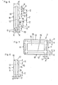
- Fig. 1 bis 4 zwei Ausführungsbeispiele eines erfindungsgemäßen Bausteines in Draufsicht und Seitenansicht,
- Fig. 5 und 6 dieselben Darstellungen einer dritten bevorzugten Ausführung,
- Fig. 7 und 8 Darstellungen eines weiteren Ausführungsbeispieles,
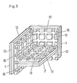
- Fig. 9 einen Teil eines aus erfindungsgemäßen Bausteinen zusammengesetzten Mauerecks und
- Fig. 10 einen Ausschnitt der beiden Schalen des Kachelofens.
- Die erfindungsgemäßen Bausteine 1 weisen bevorzugt qua- dratische Seitenflächen 14, 15 auf, wobei eine Seitenfläche 15 geschlossen und eben ist. Beim Aufbau der Innenschale eines Kachelofens werden die Bausteine 1 so versetzt, daß die geschlossenen, ebenen Seitenflächen 15 die Außenseite der Innenschalen bilden, sodaß die Kacheln 4 vollflächig ohne Ausbildung eines Luftpolsters bzw. von Luftkanälen an den Bausteinen 1 angesetzt werden können. Die hiezu verwendeten Kacheln 4 weisen selbstverständlich ebene, geschlossene Rückseiten ohne Rippen auf. Zur Verbindung der Kacheln 4 untereinander (Fig. 10) sind diese an ihren Stirnseiten 20 mit umlaufenden Nuten 18 versehen. T-förmige Verbindungsstücke 19 werden in die Nuten der Kacheln 4 eingesetzt, wobei der Mittelschenkel des T-förmigen Verbindungsstückes 19 zwei aneinander gesetzte Kacheln 4 und der Querbalken des Verbindungsstückes 19 diese mit einer Kachel 4 der nächsten Schar verbindet.
- Die Bausteine 1 sind an zwei Stirnflächen 10 mit mittleren Längsrippen 12 versehen, und weisen an den beiden anderen Stirnflächen 11 den Längsrippen 12 entsprechende Längsnuten 13 auf. Wie in den Fig. 1 bis 6 sowie 9 und 10 dargestellt, können die Längsrippen 12, bzw. die Längsnuten 13 an aneinanderstoßenden Stirnseiten oder aber nach Fig. 7 und 8 an einander gegenüberliegenden Stirnseitenvcrgesehen sein.
- Eine wesentliche Erleichterung beim Aufbau des Kachelofens wird durch Seitennuten 16, 17 erzielt, die in die andere, beim Aufbau nach innen gerichtete Seitenfläche 14 der Bausteine 1 eingelassen sind.
- In Fig. 1 und 2 ist eine erste.. Ausführung mit einer ersten Seitennut 16 dargestellt, wobei beide Randabstände x der Seitennut 16 denen der Längsnuten 13 in den Stirnflächen 11 entsprechen. Die Seitennut 16 weist eine der Längsnut 13 und damit auch der Längsrippe 12 gleiche Breite y auf, sodaß der in Fig. 1 und 2 dargestellte Baustein 1 im wesentlichen einen Würfel bildet. Zur Herstellung einer Ecke wird der Baustein 1 aus der dargestellten Lage um 90° gedreht, sodaß die Seitennut 16 vertikal verläuft. Die Längsrippe 12 der Stirnseite 10 kann somit in die Seitennut 16 eingesetzt werden.
- Die Ausführung nach Fig. 3 zeigt einen Baustein 1 mit zwei ersten Seitennuten 16 in der Seitenfläche 14, wobei beide den Randabstand x, der wiederum dem der Längsnut 13 entspricht, sowie untereinander den Abstand 2x aufweisen. Die Breite y der Seitennuten 16 entspricht wiederum der Breite der Längsnut 13. Daraus ergibt sich, daß der Mittelabstand z der beiden Seitennuten 16 der Wandstärke d, und diese der halben Höhe des Bausteines 1 entsprechen.
- Eine bevorzugte Ausführung zeigen Fig 5 und 6. Hier sind in die Seitenfläche 14 vier erste Seitennuten 16 eingelassen, die die Breite y gleich der Breite der Längsnut 13, den Mittelabstand z gleich der Wandstärke d, und den Randabstand x gleich dem der Längsnut 13 aufweisen. Zusätzlich sind vier zweite Seitennuten 17 vorgesehen, die - die. ersten Seitennuten 16 im rechten Winkel schneiden und für die dieselben Beziehungen gelten. Zwischen den Seitennuten 16, 17 verbleiben Erhebungen, deren Oberfläche im 'Eckbereich die Größe x mal x, im übrigen Randbereich die Größe x mal 2x und im Mittelbereich die Größe 2x mal 2x aufweisen.
- Dieser Baustein kann durch seine große Anzahl von Seitennuten für alle im Innenaufbau des Kachelofens notwendigen Zwischenböden, Zwischenwände für Rauchgaszüge usw.. eingesetzt werden, da, wie im Ausführungsbeispiel nach Fig. 9 gezeigt, beliebige Anordnungen in einfacher Weise hergestellt werden können.
- Der Baustein nach Fig. 7 und 8 zeigt eine weitere Variante mit rechteckigen Seitenflächen 14, 15. In die Seitenfläche 14 sind je zwei erste und zweite Seitennuten 16, 17 eingelassen, die jeweils den Randabstand x aufweisen, der wiederum dem Randabstand der Längsnut 13 bzw. Längsrippe 12 entspricht. Bei dieser Ausführung ist auch die Möglichkeit gezeigt, daß die Längsrippen 12 bzw. Längsnuten 13 an einander gegenüberliegenden Stirnflächen vorgesehen sind. Selbstverständlich könnte auch dieser Baustein mit weiteren Seitennuten versehen sein.
- Durch die erfindungsgemäßen Bausteine können zweischalige Kachelöfen, Stein für Stein vorberechnet, die benötigten Steine vorbereitet und bevorzugt zusammen mit den Kacheln 4 als Selbstbausatz verkauft werden. Die Innenschale und der Innenaufbau können ohne besondere Fachkenntnisse nach einem Verlegeplan hergestellt werden, da die Lage der einzelnen Bausteine einerseits durch die Nuten und Rippen eindeutig bestimmt, und anderseits bei mehreren Möglichkeiten ohne Schwierigkeiten vorbezeichnet werden kann.
Claims (5)
Priority Applications (1)
| Application Number | Priority Date | Filing Date | Title |
|---|---|---|---|
| AT81100460T ATE1871T1 (de) | 1981-01-22 | 1981-01-22 | Feuerfester baustein zur herstellung der inennschale und des innenaufbaues eines zweischaligen kachelofens. |
Applications Claiming Priority (2)
| Application Number | Priority Date | Filing Date | Title |
|---|---|---|---|
| WOPCT/AT80/00004 | 1980-01-31 | ||
| PCT/AT1980/000004 WO1981002190A1 (fr) | 1980-01-31 | 1980-01-31 | Elements pour la construction de poeles en faience a double paroi |
Publications (2)
| Publication Number | Publication Date |
|---|---|
| EP0033486A1 true EP0033486A1 (de) | 1981-08-12 |
| EP0033486B1 EP0033486B1 (de) | 1982-11-24 |
Family
ID=3681126
Family Applications (1)
| Application Number | Title | Priority Date | Filing Date |
|---|---|---|---|
| EP81100460A Expired EP0033486B1 (de) | 1980-01-31 | 1981-01-22 | Feuerfester Baustein zur Herstellung der Inennschale und des Innenaufbaues eines zweischaligen Kachelofens |
Country Status (5)
| Country | Link |
|---|---|
| EP (1) | EP0033486B1 (de) |
| CA (1) | CA1138736A (de) |
| DE (3) | DE8035070U1 (de) |
| NO (1) | NO149482C (de) |
| WO (2) | WO1981002190A1 (de) |
Cited By (3)
| Publication number | Priority date | Publication date | Assignee | Title |
|---|---|---|---|---|
| AT1037U1 (de) * | 1995-03-09 | 1996-09-25 | Rudolf Lonski | Baustein zur herstellung von kachelöfen und feuerungen |
| AT409185B (de) * | 2000-03-09 | 2002-06-25 | Concept Kreative Prod | Feuerfester baustein |
| AT411848B (de) * | 1996-04-01 | 2004-06-25 | Ambio Innovations Und Vertrieb | Baustein aus feuerfestem material für eine heizvorrichtung |
Families Citing this family (2)
| Publication number | Priority date | Publication date | Assignee | Title |
|---|---|---|---|---|
| AT409170B (de) * | 1996-05-24 | 2002-06-25 | Concept Kreative Prod | Innenschale eines zweischaligen kachelofens |
| DE29915038U1 (de) | 1999-08-27 | 1999-11-25 | Olsberg Hermann Everken GmbH, 59939 Olsberg | Kamin- oder Kachelofen-Anlage |
Citations (4)
| Publication number | Priority date | Publication date | Assignee | Title |
|---|---|---|---|---|
| DE188253C (de) * | ||||
| DE361537C (de) * | 1922-10-17 | Hans Rukwid | Ofenkachel mit Nut und Feder | |
| CH248628A (de) * | 1945-05-24 | 1947-05-15 | Kanthal Ab | Rechteckige Platte aus feuerfestem Material. |
| DE920986C (de) * | 1944-03-16 | 1954-12-06 | Egon Kortmann | Ofenkachelverband |
-
1980
- 1980-01-31 WO PCT/AT1980/000004 patent/WO1981002190A1/de not_active Ceased
- 1980-01-31 DE DE19808035070U patent/DE8035070U1/de not_active Expired
- 1980-01-31 DE DE19808035071U patent/DE8035071U1/de not_active Expired
- 1980-12-30 WO PCT/AT1980/000037 patent/WO1981002192A1/de not_active Ceased
-
1981
- 1981-01-22 DE DE8181100460T patent/DE3160007D1/de not_active Expired
- 1981-01-22 EP EP81100460A patent/EP0033486B1/de not_active Expired
- 1981-01-30 CA CA000369726A patent/CA1138736A/en not_active Expired
- 1981-09-21 NO NO813206A patent/NO149482C/no unknown
Patent Citations (4)
| Publication number | Priority date | Publication date | Assignee | Title |
|---|---|---|---|---|
| DE188253C (de) * | ||||
| DE361537C (de) * | 1922-10-17 | Hans Rukwid | Ofenkachel mit Nut und Feder | |
| DE920986C (de) * | 1944-03-16 | 1954-12-06 | Egon Kortmann | Ofenkachelverband |
| CH248628A (de) * | 1945-05-24 | 1947-05-15 | Kanthal Ab | Rechteckige Platte aus feuerfestem Material. |
Cited By (3)
| Publication number | Priority date | Publication date | Assignee | Title |
|---|---|---|---|---|
| AT1037U1 (de) * | 1995-03-09 | 1996-09-25 | Rudolf Lonski | Baustein zur herstellung von kachelöfen und feuerungen |
| AT411848B (de) * | 1996-04-01 | 2004-06-25 | Ambio Innovations Und Vertrieb | Baustein aus feuerfestem material für eine heizvorrichtung |
| AT409185B (de) * | 2000-03-09 | 2002-06-25 | Concept Kreative Prod | Feuerfester baustein |
Also Published As
| Publication number | Publication date |
|---|---|
| DE8035070U1 (de) | 1982-09-02 |
| DE8035071U1 (de) | 1982-06-24 |
| NO149482C (no) | 1984-05-02 |
| WO1981002190A1 (fr) | 1981-08-06 |
| NO149482B (no) | 1984-01-16 |
| DE3160007D1 (en) | 1982-12-30 |
| CA1138736A (en) | 1983-01-04 |
| NO813206L (no) | 1981-09-21 |
| WO1981002192A1 (fr) | 1981-08-06 |
| EP0033486B1 (de) | 1982-11-24 |
Similar Documents
| Publication | Publication Date | Title |
|---|---|---|
| DE2936640A1 (de) | Baustein und bauverfahren | |
| EP0033486B1 (de) | Feuerfester Baustein zur Herstellung der Inennschale und des Innenaufbaues eines zweischaligen Kachelofens | |
| EP0033485B1 (de) | Baustein zur Herstellung eines zweischaligen Kachelofens | |
| DE3532590A1 (de) | Mauerstein | |
| DE3615247C2 (de) | ||
| DE1802464A1 (de) | Baustein | |
| WO1981002193A1 (fr) | Element et serie d'elements pour la construction de poeles en faience a double paroi | |
| DE2050342C3 (de) | Baukörpergruppe | |
| DE822436C (de) | Hohlblockstein | |
| DE2249784C3 (de) | Baustein mit umlaufenden flachen Nuten und einem Fugenfüllkanal | |
| AT240568B (de) | Kaminformstein aus Leichtbeton | |
| DE2754344A1 (de) | Formsteine aus beliebigem werkstoff, beispielsweise ziegel, gasbeton o.dgl. und deren zusammenbau zu wandelementen mittels haftmittel bzw. haftmittelstreifen | |
| DE966787C (de) | Kaminformsteinsatz | |
| AT409185B (de) | Feuerfester baustein | |
| DE1609640C3 (de) | Teilbarer Betonformstein | |
| DE1953354A1 (de) | Mauerstein mit Aussparungen | |
| DE823032C (de) | Baustein und Verfahren zur Herstellung von Mauerwerk | |
| DE29904167U1 (de) | Plattenartiger Formstein für Heizanlagen | |
| DE2536323A1 (de) | Als laenglicher kubus ausgebildeter blockstein | |
| DE806482C (de) | Mauer aus in Abstand voneinander stehenden, durch Bauplatten gebildeten Schichten | |
| DE821399C (de) | Mauerwerk mit Hohlblocksteinen | |
| DE60002299T2 (de) | Aussenwandsystem aus bausteinen, sowie baustein zur verwendung in einer aussenwand | |
| DE2709336A1 (de) | Keramikblock | |
| DE2239558A1 (de) | Fertigteil fuer zwischenwaende | |
| DE1049077B (de) | Formstein fuer Schornsteinmauerwerk |
Legal Events
| Date | Code | Title | Description |
|---|---|---|---|
| PUAI | Public reference made under article 153(3) epc to a published international application that has entered the european phase |
Free format text: ORIGINAL CODE: 0009012 |
|
| AK | Designated contracting states |
Designated state(s): AT BE CH DE FR GB IT NL SE |
|
| 17P | Request for examination filed |
Effective date: 19820116 |
|
| ITF | It: translation for a ep patent filed | ||
| GRAA | (expected) grant |
Free format text: ORIGINAL CODE: 0009210 |
|
| AK | Designated contracting states |
Designated state(s): AT BE CH DE FR GB IT LI NL SE |
|
| REF | Corresponds to: |
Ref document number: 1871 Country of ref document: AT Date of ref document: 19821215 Kind code of ref document: T |
|
| REF | Corresponds to: |
Ref document number: 3160007 Country of ref document: DE Date of ref document: 19821230 |
|
| RAP2 | Party data changed (patent owner data changed or rights of a patent transferred) |
Owner name: CONCEPT GESELLSCHAFT FUER KREATIVE PRODUKTENTWICKL |
|
| ITTA | It: last paid annual fee | ||
| EAL | Se: european patent in force in sweden |
Ref document number: 81100460.5 |
|
| PGFP | Annual fee paid to national office [announced via postgrant information from national office to epo] |
Ref country code: SE Payment date: 19990118 Year of fee payment: 19 |
|
| PGFP | Annual fee paid to national office [announced via postgrant information from national office to epo] |
Ref country code: CH Payment date: 19990121 Year of fee payment: 19 |
|
| PGFP | Annual fee paid to national office [announced via postgrant information from national office to epo] |
Ref country code: BE Payment date: 19990125 Year of fee payment: 19 |
|
| PGFP | Annual fee paid to national office [announced via postgrant information from national office to epo] |
Ref country code: FR Payment date: 19990127 Year of fee payment: 19 |
|
| PGFP | Annual fee paid to national office [announced via postgrant information from national office to epo] |
Ref country code: NL Payment date: 19990131 Year of fee payment: 19 |
|
| PG25 | Lapsed in a contracting state [announced via postgrant information from national office to epo] |
Ref country code: SE Free format text: LAPSE BECAUSE OF NON-PAYMENT OF DUE FEES Effective date: 20000123 |
|
| PGFP | Annual fee paid to national office [announced via postgrant information from national office to epo] |
Ref country code: GB Payment date: 20000124 Year of fee payment: 20 |
|
| PG25 | Lapsed in a contracting state [announced via postgrant information from national office to epo] |
Ref country code: CH Free format text: LAPSE BECAUSE OF NON-PAYMENT OF DUE FEES Effective date: 20000131 Ref country code: BE Free format text: LAPSE BECAUSE OF NON-PAYMENT OF DUE FEES Effective date: 20000131 Ref country code: LI Free format text: LAPSE BECAUSE OF NON-PAYMENT OF DUE FEES Effective date: 20000131 |
|
| PGFP | Annual fee paid to national office [announced via postgrant information from national office to epo] |
Ref country code: AT Payment date: 20000131 Year of fee payment: 20 |
|
| PGFP | Annual fee paid to national office [announced via postgrant information from national office to epo] |
Ref country code: DE Payment date: 20000225 Year of fee payment: 20 |
|
| BERE | Be: lapsed |
Owner name: CONCEPT GESELLSCHAFT FUR KREATIVE PRODUKTENTWICKL Effective date: 20000131 |
|
| PG25 | Lapsed in a contracting state [announced via postgrant information from national office to epo] |
Ref country code: NL Free format text: LAPSE BECAUSE OF NON-PAYMENT OF DUE FEES Effective date: 20000801 |
|
| EUG | Se: european patent has lapsed |
Ref document number: 81100460.5 |
|
| REG | Reference to a national code |
Ref country code: CH Ref legal event code: PL |
|
| PG25 | Lapsed in a contracting state [announced via postgrant information from national office to epo] |
Ref country code: FR Free format text: LAPSE BECAUSE OF NON-PAYMENT OF DUE FEES Effective date: 20000929 |
|
| NLV4 | Nl: lapsed or anulled due to non-payment of the annual fee |
Effective date: 20000801 |
|
| REG | Reference to a national code |
Ref country code: FR Ref legal event code: ST |
|
| PG25 | Lapsed in a contracting state [announced via postgrant information from national office to epo] |
Ref country code: GB Free format text: LAPSE BECAUSE OF EXPIRATION OF PROTECTION Effective date: 20010121 |
|
| PG25 | Lapsed in a contracting state [announced via postgrant information from national office to epo] |
Ref country code: AT Free format text: LAPSE BECAUSE OF EXPIRATION OF PROTECTION Effective date: 20010122 |
|
| REG | Reference to a national code |
Ref country code: GB Ref legal event code: PE20 Effective date: 20010121 |
|
| PLBE | No opposition filed within time limit |
Free format text: ORIGINAL CODE: 0009261 |
|
| STAA | Information on the status of an ep patent application or granted ep patent |
Free format text: STATUS: NO OPPOSITION FILED WITHIN TIME LIMIT |