EP0033778A2 - Dispositif pour fixer latéralement un rouleau de machine à imprimer - Google Patents
Dispositif pour fixer latéralement un rouleau de machine à imprimer Download PDFInfo
- Publication number
- EP0033778A2 EP0033778A2 EP80107847A EP80107847A EP0033778A2 EP 0033778 A2 EP0033778 A2 EP 0033778A2 EP 80107847 A EP80107847 A EP 80107847A EP 80107847 A EP80107847 A EP 80107847A EP 0033778 A2 EP0033778 A2 EP 0033778A2
- Authority
- EP
- European Patent Office
- Prior art keywords
- bearing
- roller
- shell
- axle journals
- shells
- Prior art date
- Legal status (The legal status is an assumption and is not a legal conclusion. Google has not performed a legal analysis and makes no representation as to the accuracy of the status listed.)
- Granted
Links
Images
Classifications
-
- B—PERFORMING OPERATIONS; TRANSPORTING
- B41—PRINTING; LINING MACHINES; TYPEWRITERS; STAMPS
- B41F—PRINTING MACHINES OR PRESSES
- B41F31/00—Inking arrangements or devices
- B41F31/30—Arrangements for tripping, lifting, adjusting, or removing inking rollers; Supports, bearings, or forks therefor
- B41F31/304—Arrangements for inking roller bearings, forks or supports
Definitions
- the invention relates to a device for laterally fastening the arranged in a rotatable jacket fixed axis of a printing press roller, for. B. ink or dampening roller.
- an inking roller is designed in the form of a fixed axis with a roller shell rotatably arranged on it, the two ends of the axis, i. H. the stub axle, on both sides by means of suitable fasteners, eg. B. by means of screws.
- the object of the invention is to provide a device for lateral fastening of the fixed axis equipped with a rotating jacket of a printing press roller, which can be used both in a simple manner in the printing press and enables an automatic circumferential alignment of the axis, so that for the fastening process Axis is brought into a defined position to the bearings that receive it.
- the hollow cylindrical bearing shells receiving the axle journals are at least partially half-shell-shaped and in that the axle journals are each provided with a locking pin passing through them for circumferential alignment of the axis in the bearing shells, so that they are arranged at right angles to the locking pins in the axle journals Fastening screws when inserting the roller can be aligned with threaded holes provided in the bearing shells.
- the fastening device enables the roller to be fixed without tension in the bearing shells arranged on both sides.
- a particularly advantageous development of the one bearing point as a floating bearing additionally offers the roller axis the possibility of axially expanding, for example when heated, with the roller being permanently pressed against the fixed bearing on the other side.
- a special arrangement of the locking pins and fastening screws inserted into the two axle journals ensures that the fastening screws do not fall out and enter the machine can be long.
- the design of the bearing shells with bevels also facilitates the insertion process of the roller into the printing press.
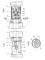
- the inking roller 1 shown in Figures 1 to 3 consists of a jacket 2 which is rotatably arranged on a fixed axis 3. 1 and 2, the axis 3 is equipped on both sides with bearings 4 and 5, on which the jacket 2 is mounted.
- the left axle journal 6 and the right axle journal 7 are fixed in a bearing shell 8 and in a bearing shell 9, respectively.
- the bearing shells 8 and 9 consist of tubular parts, each with a web arranged in the middle.
- a screw 10 engages through the web of the bearing shell 8, through which the bearing shell 8 can be screwed with a bearing pin 11 engaging in it.
- a collar screw 12 which carries a plate spring 13, engages through the web of the bearing shell 9. With the collar screw 12, the bearing shell 9 can be screwed onto a bearing journal 14.
- seated plate spring is, however, in contrast to the fixed bearing on the left side of FIG. 1, the bearing of FIG. 2 on the right side as a floating bearing, since the bearing shell 9 is axially movable, the axial play by the collar screw 12 is adjustable.
- the bearing journals 11 and 14 are arranged eccentrically in order, for example, to be able to position the inking roller 1 against a further roller which runs parallel to the latter (not shown).
- the inward ends of the bearing shells 8 and 9 are milled off to the middle, whereby support areas for the two journals 6 and 7 are formed.
- the lifting bevels leading to these areas make the insertion of the inking roller 1 considerably easier.
- axle journals 6 and 7 are provided with screws 15 and 16, by means of which the axis 3 can be fixed in the half-shell-shaped regions of the bearing shells 8 and 9 after the inking roller 1 has been inserted.
- a special feature of the invention consists in the use of locking pins 17 and 18 in the axle journals 6 and 7.
- the locking pins 17 and 18 extend approximately at right angles, i. H. transverse to the screws 15 and 16 through the axis 3 and protrude from this on both sides.
- the locking pins 17 and 18 are arranged directly on the screw regions, each screwed off between the screw head and the thread screw-in length, down to the core cross-section, so that the clear width of the bore for the screws 15 and 16 through the locking pins 17 and 18 is limited to prevent the screws 15 and 16 from falling out of the journal 6 and 7. This avoids the risk that the screws 15 and 16 fall into the machine when the roller 1 is inserted.
- the bearing shell 8 is rotatable on the journal 11 and can thus be rotated into a desired circumferential position suitable for the insertion process of the inking roller, after which the bearing shell 8 is fixed to the journal 11 by tightening the screw.
- the collar screw 12 With the plate spring 13 arranged on it, an adjustment of the axial play of the bearing shell 9 on the journal 12 is possible.
- the locking pin 17 first lies on the milled lower area of the circumferentially and axially fixed bearing shell 8, as a result of which the axis 3 of the inking roller 1 is rotated into the desired circumferential position, in which the screw 15 with the one in the bearing shell 8 provided threaded hole (only shown in Fig. 2) is aligned. Since the bearing shell 9 is rotatably arranged on the journal 14, this also aligns when the inking roller is inserted by the locking pin 18, so that the threaded bore provided in the bearing shell 9 is aligned with the screw 16.
- the inking roller 1 is now seated in the desired position in the bearing shells 8 and 9, and is constantly pressed against the left-hand fixed bearing (FIG. 1) by the plate spring 13.
- the inking roller 11 can now be attached in a simple manner by tightening the screws 15 and 16.
- the non-locating bearing (FIG. 2) enables an axial movement, so that, for example, when the inking roller 1 heats up, the associated stretching process is made possible without the inking roller 1 being braced.
- another elastic element for example a rubber ring, can also be used.
- the protective sleeves 19 and 20 are used to reduce the risk of contamination of the fastening points shown in FIGS. 1 and 2.
- the protective sleeve 19 in the form of a tubular part comprises the bearing shell 8, the bearing pin 11, the screw 15, the locking pin 17 and the left axle pin 6.
- the protective sleeve 20 comprises the bearing shell 9, the screw 16, the locking pin 18, the bearing pin 14 and the right axle pin 7.
- the protective sleeves 19 and 20 have recesses. By turning the protective sleeves 19 and 20, the recesses move upward, so that the inking roller 11 can be inserted and the fastening elements described are accessible. After the insertion and mounting operation is completed, then a twist of the sleeves 19 and 20 is achieved by 180 0 whereby an exact cover the fasteners.
Landscapes
- Inking, Control Or Cleaning Of Printing Machines (AREA)
- Rolls And Other Rotary Bodies (AREA)
Applications Claiming Priority (2)
| Application Number | Priority Date | Filing Date | Title |
|---|---|---|---|
| DE3004921A DE3004921C2 (de) | 1980-02-09 | 1980-02-09 | Vorrichtung zum seitlichen Befestigen einer Druckmaschinenwalze |
| DE3004921 | 1980-02-09 |
Publications (3)
| Publication Number | Publication Date |
|---|---|
| EP0033778A2 true EP0033778A2 (fr) | 1981-08-19 |
| EP0033778A3 EP0033778A3 (en) | 1981-08-26 |
| EP0033778B1 EP0033778B1 (fr) | 1984-04-18 |
Family
ID=6094246
Family Applications (1)
| Application Number | Title | Priority Date | Filing Date |
|---|---|---|---|
| EP80107847A Expired EP0033778B1 (fr) | 1980-02-09 | 1980-12-12 | Dispositif pour fixer latéralement un rouleau de machine à imprimer |
Country Status (4)
| Country | Link |
|---|---|
| US (1) | US4329922A (fr) |
| EP (1) | EP0033778B1 (fr) |
| JP (1) | JPS56126166A (fr) |
| DE (1) | DE3004921C2 (fr) |
Families Citing this family (1)
| Publication number | Priority date | Publication date | Assignee | Title |
|---|---|---|---|---|
| DE3805143C1 (fr) * | 1988-02-19 | 1989-03-23 | Man Roland Druckmaschinen Ag, 6050 Offenbach, De |
Family Cites Families (11)
| Publication number | Priority date | Publication date | Assignee | Title |
|---|---|---|---|---|
| DD42342A (fr) * | ||||
| CH113555A (de) * | 1924-03-31 | 1926-01-16 | Maschf Augsburg Nuernberg Ag | Einrichtung zur Sicherung des Lagerzapfens an Farbwalzen von Druckereimaschinen. |
| DE413079C (de) * | 1924-08-06 | 1925-05-01 | Albert Schnellpressen | Lagerung fuer Farbwalzen, Spindeln u. dgl. an Druckmaschinen |
| US2775935A (en) * | 1954-02-16 | 1957-01-01 | Maschf Augsburg Nuernberg Ag | Register adjustment for printing machines |
| DE1047213B (de) * | 1956-07-17 | 1958-12-24 | Maschf Augsburg Nuernberg Ag | Lagerung der Zylinder von Druckmaschinen |
| DE1824024U (de) * | 1960-09-03 | 1960-12-29 | Planeta Veb Druckmasch Werke | Anordnung zur lagerung von auftragswalzen fuer druckmaschinen. |
| CH421145A (de) * | 1962-08-02 | 1966-09-30 | Planeta Veb Druckmasch Werke | Vorrichtung zur Registereinstellung bei Druckmaschinen |
| DE1887338U (de) * | 1963-11-22 | 1964-02-13 | Maschf Augsburg Nuernberg Ag | Walzenlager fuer farb- und feuchtwalzen von druckwerken. |
| GB1205587A (en) * | 1967-03-04 | 1970-09-16 | Baker Perkins Ltd | Improvements relating to printing press inking mechanisms |
| JPS5931467B2 (ja) * | 1977-04-27 | 1984-08-02 | 株式会社東京機械製作所 | 輪転印刷機における版胴装置 |
| US4214528A (en) * | 1978-08-25 | 1980-07-29 | White Consolidated Industries, Inc. | Plate cylinder side register adjustment |
-
1980
- 1980-02-09 DE DE3004921A patent/DE3004921C2/de not_active Expired
- 1980-12-12 EP EP80107847A patent/EP0033778B1/fr not_active Expired
-
1981
- 1981-02-03 US US06/231,161 patent/US4329922A/en not_active Expired - Lifetime
- 1981-02-09 JP JP1704781A patent/JPS56126166A/ja active Granted
Also Published As
| Publication number | Publication date |
|---|---|
| DE3004921A1 (de) | 1981-10-08 |
| DE3004921C2 (de) | 1982-07-22 |
| JPH0330498B2 (fr) | 1991-04-30 |
| JPS56126166A (en) | 1981-10-02 |
| EP0033778A3 (en) | 1981-08-26 |
| EP0033778B1 (fr) | 1984-04-18 |
| US4329922A (en) | 1982-05-18 |
Similar Documents
| Publication | Publication Date | Title |
|---|---|---|
| DE4038920C1 (fr) | ||
| DE9116367U1 (de) | Zylinder für die Papierführung an Bogenrotationsdruckmaschinen | |
| DE2653236C3 (de) | Vorrichtung zum Innenentgraten längsnahtgeschweißter Rohre | |
| DE2916251A1 (de) | Saugluftbeaufschlagte hohlwalze fuer druckmaschinen | |
| CH438995A (de) | Maschine zum Schleifen der Schneidkanten von Stanzwerkzeugen | |
| DE29617401U1 (de) | Vorrichtung zum Verbinden/Lösen eines Walzenkörpers in Rotationsdruckmaschinen | |
| DE2720673B2 (de) | Vorrichtung zum ungleichförmigen Spannen eines Gummituches in einer Offsetdruckmaschine | |
| DE2029007C3 (de) | Vorrichtung zum Einstellen der Druckkraft einer in Haltern gelagerten Auftragwalze eines Feuchtwerkes einer Offsetdruckmaschine | |
| DE3337265A1 (de) | Fraesvorrichtung mit einer hand-oberfraese | |
| DE3004921C2 (de) | Vorrichtung zum seitlichen Befestigen einer Druckmaschinenwalze | |
| DE3318994C1 (de) | Abrolleinrichtung | |
| DE2753284C2 (de) | Schmitzringanordnung zwischen zwei Druckwerkszylindern | |
| DE3115141C2 (de) | Vorrichtung zum Diagonalverstellen eines Zylinders einer Druckmaschine, vorzugsweise des Plattenzylinders einer Bogenrotations-Offsetdruckmaschine | |
| DE10035001B4 (de) | Leitwalze | |
| DE19757815C1 (de) | Walze | |
| DE2842000A1 (de) | Vorrichtung zum spannen des gummituches auf dem gummizylinder von rotationsdruckmaschinen | |
| EP0983846B1 (fr) | Machine rotative d'impression | |
| EP0531658B1 (fr) | Chappe de rouleau pour rouleaux de caoutchouc dans des machines à imprimer | |
| DE9316916U1 (de) | Kombiniertes Feucht-Farbwerk | |
| DE10152467A1 (de) | Walzenschloss | |
| DE483217C (de) | Farbwalzenlager fuer Druckmaschinen, bei dem die Farbwalzenlagerhuelse zum Verstellen der Farbwalze um einen Punkt ihrer Achse geschwenkt wird | |
| DE3937788C1 (fr) | ||
| DE1124051B (de) | Vorrichtung zum Befestigen des Gummituches auf dem Gummizylinder | |
| DE102010001165B4 (de) | Schnellwechseleinrichtung einer Papierleitwalze einer Rotationsdruckmaschine | |
| DE3915848A1 (de) | Lageranordnung |
Legal Events
| Date | Code | Title | Description |
|---|---|---|---|
| PUAI | Public reference made under article 153(3) epc to a published international application that has entered the european phase |
Free format text: ORIGINAL CODE: 0009012 |
|
| PUAL | Search report despatched |
Free format text: ORIGINAL CODE: 0009013 |
|
| AK | Designated contracting states |
Designated state(s): CH FR IT SE |
|
| AK | Designated contracting states |
Designated state(s): CH FR IT SE |
|
| 17P | Request for examination filed |
Effective date: 19810904 |
|
| ITF | It: translation for a ep patent filed | ||
| GRAA | (expected) grant |
Free format text: ORIGINAL CODE: 0009210 |
|
| AK | Designated contracting states |
Designated state(s): CH FR IT LI SE |
|
| ET | Fr: translation filed | ||
| PLBE | No opposition filed within time limit |
Free format text: ORIGINAL CODE: 0009261 |
|
| STAA | Information on the status of an ep patent application or granted ep patent |
Free format text: STATUS: NO OPPOSITION FILED WITHIN TIME LIMIT |
|
| 26N | No opposition filed | ||
| ITTA | It: last paid annual fee | ||
| PGFP | Annual fee paid to national office [announced via postgrant information from national office to epo] |
Ref country code: CH Payment date: 19931115 Year of fee payment: 14 |
|
| PGFP | Annual fee paid to national office [announced via postgrant information from national office to epo] |
Ref country code: SE Payment date: 19931116 Year of fee payment: 14 |
|
| PGFP | Annual fee paid to national office [announced via postgrant information from national office to epo] |
Ref country code: FR Payment date: 19931119 Year of fee payment: 14 |
|
| PG25 | Lapsed in a contracting state [announced via postgrant information from national office to epo] |
Ref country code: SE Effective date: 19941213 |
|
| PG25 | Lapsed in a contracting state [announced via postgrant information from national office to epo] |
Ref country code: LI Effective date: 19941231 Ref country code: CH Effective date: 19941231 |
|
| EAL | Se: european patent in force in sweden |
Ref document number: 80107847.8 |
|
| PG25 | Lapsed in a contracting state [announced via postgrant information from national office to epo] |
Ref country code: FR Effective date: 19950831 |
|
| REG | Reference to a national code |
Ref country code: CH Ref legal event code: PL |
|
| EUG | Se: european patent has lapsed |
Ref document number: 80107847.8 |
|
| REG | Reference to a national code |
Ref country code: FR Ref legal event code: ST |