EP0033781A2 - Système de détection de compresseur défaillant et de commande pour une pompe de chaleur - Google Patents
Système de détection de compresseur défaillant et de commande pour une pompe de chaleur Download PDFInfo
- Publication number
- EP0033781A2 EP0033781A2 EP80108165A EP80108165A EP0033781A2 EP 0033781 A2 EP0033781 A2 EP 0033781A2 EP 80108165 A EP80108165 A EP 80108165A EP 80108165 A EP80108165 A EP 80108165A EP 0033781 A2 EP0033781 A2 EP 0033781A2
- Authority
- EP
- European Patent Office
- Prior art keywords
- compressor
- temperature
- value
- controller
- outdoor coil
- Prior art date
- Legal status (The legal status is an assumption and is not a legal conclusion. Google has not performed a legal analysis and makes no representation as to the accuracy of the status listed.)
- Granted
Links
Images

Classifications
-
- F—MECHANICAL ENGINEERING; LIGHTING; HEATING; WEAPONS; BLASTING
- F25—REFRIGERATION OR COOLING; COMBINED HEATING AND REFRIGERATION SYSTEMS; HEAT PUMP SYSTEMS; MANUFACTURE OR STORAGE OF ICE; LIQUEFACTION SOLIDIFICATION OF GASES
- F25B—REFRIGERATION MACHINES, PLANTS OR SYSTEMS; COMBINED HEATING AND REFRIGERATION SYSTEMS; HEAT PUMP SYSTEMS
- F25B49/00—Arrangement or mounting of control or safety devices
- F25B49/02—Arrangement or mounting of control or safety devices for compression type machines, plants or systems
Definitions
- the invention relates to a compressor fault detection and control system for a reverse cycle refrigeration apparatus for heating and cooling an enclosed space and comprising a refrigerant compressor, compressor control means, an indoor coil, an outdoor coil and refrigerant conduits interconnecting said compressor and said coils.
- the control system comprises outdoor coil temperature sensing means having an output indicative of outdoor coil temperature, compressor discharge sensing means having an output indicative of the temperature of the refrigerant discharge from the refrigerant compression means, building temperature sensing means having an output indicative of a demand for heating or cooling of the building, and a special controller means.
- the special controller means has operative connections to the above recited temperature sensing means so as to receive the outputs thereof.
- the controller has a timing function which is initiated upon the starting or commencement of operation of the compressor.
- the controller means further includes a circuit connection-disconnection means for selectively interconnecting the building temperature sensing means to the refrigerant compression control means, the building temperature sensing means output normally being connected to the refrigerant compression control means so as to cause the compressor to run or operate whenever there is a demand for heating or cooling of the building.
- the controller means further is characterized by being adapted to inhibit the operation of the compressor means if, after a predetermined time interval as measured by the timing means, the value of the discharge temperature is less than the value of the outdoor coil temperature plus a preselected constant K 1 .
- the invention may further include a compressor "stop" detection means i.e., a means of monitoring the operation of the compressor after the above described start-up fault detection means has already established that the compressor had started in a satisfactory manner and operative to signal a malfunction if the compressor subsequently ceases to operate in the normal manner.
- a compressor "stop" detection means i.e., a means of monitoring the operation of the compressor after the above described start-up fault detection means has already established that the compressor had started in a satisfactory manner and operative to signal a malfunction if the compressor subsequently ceases to operate in the normal manner.
- the present invention provides (i) a means of detecting, within a preselected time, when a compressor has started and is correctly compressing, and (ii) a means of detecting when the compressor has stopped from a running condition; the two means may be used separately, together, and/or in conjunction with other control apparatus.
- the reverse cycle refrigeration system comprises an indoor heat exchange coil 10, an outdoor heat exchange coil 12, and refrigerant compression means or compressor 14, a compressor controller 15 energized from an appropriate source 17 of electrical energy, and refrigerant conduit means interconnecting the coils and compressor, the conduit means including the usual reversing valve 16 having a controller 18, an expansion means 20, and appropriate interconnecting piping 21-26.
- the system above described is representative of prior art systems such as that shown in the U.S. Patent 3,170,304. As is well known, such systems function whenever the building thermostat ts calling for heating or cooling to cause the compressor 14 to operate.
- the compressed hot refrigerant from the compressor 14 will be routed through the reversing valve 16 toward the indoor heat exchange coil 10 where its heat is given up to heat indoor air. Conversely, if' cooling of the building is being demanded, then the hot refrigerant from the compressor is routed through the reversing valve to the outdoor heat exchange coil where the refrigerant is cooled for subsequent use indoors to cool the building.
- the compressor fault detection and control system as depicted in Figure 1 comprises an outdoor heat exchange coil temperature sensing means 31 (hereinafter sometimes referred to as "TODCS") having an output 32 on which is a signal indicative of the outdoor heat exchange coil temperature (hereinafter sometimes referred to as "TODC").
- TODC on 32 comprises one of two inputs to a multiplexer 40 to be described in more detail below.
- the compressor fault detection and control system further comprises a compressor discharge refrigerant temperature sensing means (hereinafter sometimes referred to as "TDSCHS”) 34 having an output 35 (connected to multiplexer 40 as the second input thereof) on which is a signal indicative of the temperature of the refrigerant on the discharge side of compressor 14, said temperature hereinafter sometimes being referred to as "TDSCH”.
- TDSCHS compressor discharge refrigerant temperature sensing means
- the detection and control system further includes a room thermostat 42 (hereinafter sometimes referred to as "STAT") which responds to the temperature of a room or space in a building or the like, the temperature of which is to be controlled by the reverse cycle refrigeration system.
- Room thermostat 42 is depicted as having a first output 43 connected to the control 18 for the reversing valve 16 and a second output 44 connected to a microprocessor 50 and also, through a set of normally closed contacts 46 and a connection means 45, to the controller 15 of compressor 14.
- Contacts 46 are contained within a subsection 47 of the micro- processor 50 and both 47 and 50 will be described in more detail below.
- Model T872 heating-cooling thermostat may be used for the room thermostat 42 depicted in Figure 1, the Model T872 being of the bimetal operated mercury switch type including switch means for providing the heating-cooling control signals and also for controlling a plurality of auxiliary heating means.
- a control signal is effectively supplied on outputs 43 and 44 thereof, the control signal at 43 functioning to position via control 18 the reversing valve 16 to the proper orientation for either, heating or cooiing of the building and the control signal at 44 being transmitted through the normally closed contacts 46 and connection 45 to control the compressor 14 from a rest or "off" position to an operating or “on” condition.
- the control signal at 44 is also applied to the microprocessor 50 to indicate a demand for compressor 14 operation.
- Honeywell Inc. platinum film resistance type temperature sensor models C800A and C800C may be used for TODCS 31 and TDSCHS 34 respectively.
- a Westinghouse Inc. HI-RE-LI unit comprising an outdoor unit model No. HL036COW and indoor unit AG012HOK may be used for the basic heat pump unit depicted in Figure 1; i.e., components 10, 12, 14, 15, and 16.
- Multiplexer 40 thus has applied thereto at 32 and 35 analog_ signals representative of TODC and TDSCH respectively.
- the function of the multiplexer 40 is to supply one or the other ' of the two input.signals in analog form to the output 53 thereof, depending upon the nature of a control signal being applied to the multiplexer 40 via a lead 52 from the microprocessor 50; i.e., the microprocessor provides a control for the multiplexer 40 to select which of the two input signals is applied to output 53.
- Output 53 is applied as the input to a standard analog-to-digital converter 54 (hereinafter sometimes referred to as "A/D") having an output 55 connected as a second input to the microprocessor 50 and also having an input 56 for receiving controlling instructions from the microprocessor 50.
- A/D converter 54 having an output 55 connected as a second input to the microprocessor 50 and also having an input 56 for receiving controlling instructions from the microprocessor 50.
- the output from A/D converter 54 at output 55 is a signal in digital form indicative
- the microprocessor has a first output 60 connected to the control 18 of the reversing valve 16 so as to, if desired, control the reversing valve independently of the control supplied to 18 from the room thermostat 42.
- the microprocessor 50 has a second output 62 connected to a suitable fault indicator 63 such as a warning light and/or audible alarm or the like.
- the apparatus further includes a suitable fault reset means 65 (such as a switch) having an output 66 which constitutes a third input to the microprocessor 50.
- a suitable microprocessor that may be used in the present invention as a component of the system depicted in Figure 1 is the Intel Corporation Model 8049; a suitable representative analog-to-digital converter for use to provide the function of block 54 in Figure 1 is the Texas Instrument Inc. Model TL505C (see TI Bulletin DL-S 12580); and an appropriate multiplexer is the Motorola Inc. Model MC14051BP.
- the temperature-of the refrigerant at the compressor discharge begins to rise from its steady state off condition near the compressor ambient air temperature.
- the coil temperature changes; getting colder than ambient in the heating mode and warmer than ambient in the cooling mode. In a short period, typically less than five minutes, these temperatures reach their steady state operating values. If the compressor fails to pump refrigerant properly, the difference between the two temperatures will not be established within the normal settling time. The presence of a temperature difference can be-detected and used as a criterion for proving that the compressor is running.
- the minimum temperature difference may be determined in one of two ways.
- the first method uses a single difference criterion which accounts for the fact that the difference is reduced in the cooling mode due to the increase in outdoor coil temperature.
- the second method uses two setpoints, one for the heating mode with a wide difference and another for the cooling mode with a narrower difference.
- the mode can be detected by monitoring the control signal 43 from room thermostat 42 to reversing valve control 18.
- the mode can be detected by monitoring the outdoor coil temperature and making certain assumptions about heat pumps and building control. The major assumption is that the heat pump is most likely heating below a certain coil temperature (typically 18 0 C) and it is cooling above this temperature.
- Compressor start up may be proved by comparing the discharge-to-coil temperature difference with the appropriate setpoint after a minimum settling time from a call for compressor.
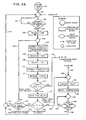
- an entry point 101 "system turns on” reflects the status of the heat pump being powered up; i.e., power 17 being applied to compressor-controller 15 and any required control system electrical energization also being supplied.
- the system flows thence via a junction 99 and thence to logic instruction block 102 to a logic instruction block 102 "thermostat calls for compressor?" having a "no" response 103 causing flow back to junction 99 where the compressor waits for the STAT to call for compressor operation, and a "yes" response 104 (indicating a call by the STAT for compressor 14 to operate) which flows to an instruction block 105 "record time as T 1 .”
- This initiates or starts a timer within microprocessor 50 to enable an elapsed time measurement (T2-Tl) operation as will be discussed below.
- the flow from 105 is through a junction 106 and thence to an instruction block 107 "connect TODCS to analog-to-digital convertor (A/D)", the flow from which is through an instruction block 108 “measure TODC”, the flow from which is to instruction block 109 “select K l ", the flow from which is to instruction block 110 "connected TDSCHS to A/D”, the flow from which is to instruction block 111 “measure TDSCH”, the flow from which is to a logic instruction block 115 "TDSCH is greater than TODC plus K 1?
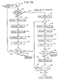
- Logic instruction block 152 has a "no" response 153 flowing to an instruction block 170 “note time as T3" flow from which is through a junction 171 to an instruction block 172 "connect TDSCHS to A/D” flow from which is to an instruction block 173 "measure TDSCH” flow from which is to an instruction block 174 "connect TODCS to A/D” flow from which is to an instruction block 175 "measure TODC” flow from which is to an instruction block 176 “select K 4 " flow from which is to a logic instruction block 177 "TDSCH is greater than TODC plus K4?" having a "no” response 178 which is adapted to be connected tc junction 99 and a “yes” response 179 flowing to an instruction block 181 "note time as T4" flow from which is to a logic instruction block 182 "T 4 - T3 is greater than K 5 ?” having a "no” response 183 connected to junction 171 and a “yes” response 184 connected to junction 130.
- the logic instruction block 115 has a "no" response 116 (indicating that the compressor start has not been proved) which flows to an instruction block 118 "note time as T 2 ".
- the "no" response 116 indicates that the appropriate temperature difference K 1 has not been reached to indicate that the compressor is operating.
- a “yes” response l19 indicates that this differential has been reached and that the compressor is operating correctly.
- the flow from instruction block 118 is to a logic instruction block 125 "T2 minus Tl is greater than K 2 " having a "yes” response 126 and a “no” response 127.
- "Yes” response 126 thus represents the situation of a faulty compressor; i.e., after a predetermined or preselected period of time (T2 minus Tl is greater than K 2 ; we have found 5 minutes an appropriate value) the compressor has not functioned to raise the discharge tempera- . ture to a sufficiently high level as is proved by the functioning of logic instruction block 115.
- the "yes" response 126 is applied via a junction 130 to an instruction block 131 "indicate fault” (this causes actuation of indicator 63) flow from which is to an instruction block 132 "inhibit compressor”. This then is effective to cause the normally open contacts 46 (of subsection 47 of microprocessor 50) to open so as to interrupt the control of compressor controller 15 by the STAT 42, and to inhibit further compressor operation.
- logic instruction block 115 has a "yes” or "fault” response if TDSCH is not greater than TODC plus the preselected constant K l , the value of which is selected according to the specifics of the actual equipment used.
- the "no" response 127 thereof flows to a logic instruction block 144 "thermostat calls for compressor?" having a "yes" response 145 and a “no” response 146.
- a "yes" response at 145 will flow to junction 106 and the system will continue to recycle with the timer and temperature difference functions continuing so that time T2 will increase until eventually either the equations of instructions 115 or 125 results in a "yes" response at 119 or 126 respectively as aforesaid, indicating that either the compressor 14 has started properly or that it has not started properly in the allowed time K2
- a means 65 e.g., a reset switch, is provided in the system to reset the entire fault detection and control system subsequent to a fault being detected and fault indicator 63 being actuated.
- logic instruction block 134 receives the flow from instruction block 132 via a junction 133.
- Logic instruction block 134 "has fault reset and activated?" has a "no" response 135 flowing back to the junction 133 and thence to block 134, indicating that "reset” has not been requested, and a "yes” response 136 flowing via 140 and 147 to instructions 136 "enable compressor” and 137 "stop indication fault” and thence via junction 9.9 to logic instruction 102 so as to restart the system.
- the apparatus depicted in Figure 2A is representative of the operation of the compressor fault detection and control system (through the primary control of the microprocessor 50) to determine whether or not the compressor 14 has actually started and is actually compressing the refrigerant in the system within a preselected time interval after STAT 42 calls for compressor 14 operation.
- This time interval gives the compressor an opportunity to raise TDSCH to the level indicative of proper compressor operation, i.e., to a level above TODCS.
- logic instruction block 102 has a "yes" response at 104 when the thermostat is calling for a compressor operation; that logic instructions 107-111 relate to the measurement of TODC and TDSCH and selection of the appropriate minimum temperature Kl to prove that the compressor 14 is operating following which logic instruction block 115 determines whether or not the refrigerant discharge temperature TDSCH is greater than the outdoor coil temperature TODC plus the constant K 1 .
- a "yes" response 119 from 115 is indicative of the compressor not only operating but operating in the normal fashion; i.e.., compressing the refrigerant. To explain further, when the compressor is functioning in the normal mode, the compressing of the refrigerant causes a substantial increase in the temperature of the refrigerant.
- a "no" response 116 from 115 causes flow to logic instruction block 125 which has a “yes” response 126 flowing therefrom to 130 when the preselected time interval has elapsed; thus, if the discharge temperature TDSCH is not hot enough after the time interval, the "yes" response 126 causes the indication of a fault through the functioning of instruction block 131 causing the actuation of the fault indicator 63 of Figure 1 and simultaneously the inhibiting of the compressor 132 which, as explained above, causes the opening of the normally closed contact 46 so as to remove control of the compressor controller 15 from STAT 42.
- the fault detection and control system also functions to monitor the operation of the heat pump system during a compressor run; i.e., following the initial determination (described above) that the compressor not only is operating but is actually compressing.
- the "yes" response 119 from logic instructi'bn block 115 flows to junction 151.
- the apparatus d.epicted in Figure 2B is in part representative of the function of periodically measuring the discharge temperature TDSCH and the outdoor coil temperature TODC, then making comparisons of such successive temperature measurements and signaling a fault and inhibiting the further operation of the compressor if it is found that the most recent discharge temperature is less than, or colder than, the outdoor coil temperature measurement plus a preselected constant K 3 .
- the "yes" response 119 from logic instruction block 115 flows through junction 151 to logic instruction block 152 to determine whether or not the thermostat 42 is still calling for compressor action; if this is the case then the "yes" response at 154 causes the functions identified at 160, 161, 162, 163, and 164 to occur enabling the logic block 165 to function i.e., the determination of whether the discharge temperature is greater than the sum of TODC plus K 3 .
- K 3 is selecced so that the output from 165 will be a "yes" when the system is operating normally i.e., the compressor is running so as to compress the refrigerant so that the temperature of the discharge will be high enough so that the equation of 165 will produce a "yes” at 166 continuing the flow back to 151.
- the flow from 165 is a "no" response as at 167 then such flow goes directly to junction 130 and thence to 131 and 132 to respectively indicate a fault at fault indicator 63 and as so inhibit the operation of the compressor as described above.
- the flow is to 181 so that a second time can be noted as time T4 flow from which is to logic instruction block 182 wherein if it is determined that the time T4 minus the previously noted time T3 is greater than a constant K5 then the "yes" response as at 181 will flow to 130 so as to signal the fault at 131 and inhibit th p compresser as at 132 as previously described.
- a no response from 182 as at 183 flows back to junction 171 to continue the cycle until such time as either a "yes" response flows at 181 from 182 or a no response flows at 178 back to junction 99 as described.
- an Intel Model 8049 microprocessor may be used to practice the subject invention; as an assistance, reference may be made to "INTELR M CS-48TM Family of Single Chip Microcomputers -- User's Manual", a 1978 copyrighted manual of the Intel Corporation, Santa Clara, California 95051.
Landscapes
- Engineering & Computer Science (AREA)
- Physics & Mathematics (AREA)
- Mechanical Engineering (AREA)
- Thermal Sciences (AREA)
- General Engineering & Computer Science (AREA)
- Air Conditioning Control Device (AREA)
- Control Of Positive-Displacement Pumps (AREA)
- Compression-Type Refrigeration Machines With Reversible Cycles (AREA)
Applications Claiming Priority (2)
| Application Number | Priority Date | Filing Date | Title |
|---|---|---|---|
| US120454 | 1980-02-11 | ||
| US06/120,454 US4301660A (en) | 1980-02-11 | 1980-02-11 | Heat pump system compressor fault detector |
Publications (3)
| Publication Number | Publication Date |
|---|---|
| EP0033781A2 true EP0033781A2 (fr) | 1981-08-19 |
| EP0033781A3 EP0033781A3 (en) | 1982-05-19 |
| EP0033781B1 EP0033781B1 (fr) | 1984-10-24 |
Family
ID=22390396
Family Applications (1)
| Application Number | Title | Priority Date | Filing Date |
|---|---|---|---|
| EP80108165A Expired EP0033781B1 (fr) | 1980-02-11 | 1980-12-23 | Système de détection de compresseur défaillant et de commande pour une pompe de chaleur |
Country Status (4)
| Country | Link |
|---|---|
| US (1) | US4301660A (fr) |
| EP (1) | EP0033781B1 (fr) |
| JP (1) | JPS56130564A (fr) |
| DE (1) | DE3069531D1 (fr) |
Cited By (4)
| Publication number | Priority date | Publication date | Assignee | Title |
|---|---|---|---|---|
| WO1986003281A1 (fr) * | 1983-06-02 | 1986-06-05 | Enstroem Henrik Sven | Procede et dispositif destine principalement au controle du rendement des pompes a chaleur ou des installations frigorifiques |
| EP0257576A3 (en) * | 1986-08-26 | 1989-11-02 | Uhr Corporation | Method and apparatus for avoiding failures caused by contacts-welding in heating and cooling systems |
| EP1756485A4 (fr) * | 2004-06-07 | 2010-03-24 | Carrier Corp | Procede de controle d'un systeme de chauffage d'eau d'une thermopompe a gaz carbonique |
| US12085295B2 (en) | 2022-03-28 | 2024-09-10 | Trane International Inc. | Heat pump fault detection system |
Families Citing this family (33)
| Publication number | Priority date | Publication date | Assignee | Title |
|---|---|---|---|---|
| US4627483A (en) * | 1984-01-09 | 1986-12-09 | Visual Information Institute, Inc. | Heat pump control system |
| US4627484A (en) * | 1984-01-09 | 1986-12-09 | Visual Information Institute, Inc. | Heat pump control system with defrost cycle monitoring |
| US4574871A (en) * | 1984-05-07 | 1986-03-11 | Parkinson David W | Heat pump monitor apparatus for fault detection in a heat pump system |
| US5440890A (en) * | 1993-12-10 | 1995-08-15 | Copeland Corporation | Blocked fan detection system for heat pump |
| US5440895A (en) * | 1994-01-24 | 1995-08-15 | Copeland Corporation | Heat pump motor optimization and sensor fault detection |
| US5623834A (en) * | 1995-05-03 | 1997-04-29 | Copeland Corporation | Diagnostics for a heating and cooling system |
| WO2005065355A2 (fr) | 2003-12-30 | 2005-07-21 | Copeland Corporation | Systeme de diagnostic et de protection de compresseur |
| US7380588B2 (en) * | 2004-01-12 | 2008-06-03 | Trane International Inc. | Heat pump control system and method of operating to provide automatic backup heating modes |
| US7412842B2 (en) | 2004-04-27 | 2008-08-19 | Emerson Climate Technologies, Inc. | Compressor diagnostic and protection system |
| US7275377B2 (en) | 2004-08-11 | 2007-10-02 | Lawrence Kates | Method and apparatus for monitoring refrigerant-cycle systems |
| US7234311B2 (en) * | 2005-04-04 | 2007-06-26 | Carrier Corporation | Prevention of compressor unpowered reverse rotation in heat pump units |
| US8590325B2 (en) | 2006-07-19 | 2013-11-26 | Emerson Climate Technologies, Inc. | Protection and diagnostic module for a refrigeration system |
| US20080216494A1 (en) | 2006-09-07 | 2008-09-11 | Pham Hung M | Compressor data module |
| US20090037142A1 (en) | 2007-07-30 | 2009-02-05 | Lawrence Kates | Portable method and apparatus for monitoring refrigerant-cycle systems |
| US8393169B2 (en) * | 2007-09-19 | 2013-03-12 | Emerson Climate Technologies, Inc. | Refrigeration monitoring system and method |
| US9140728B2 (en) | 2007-11-02 | 2015-09-22 | Emerson Climate Technologies, Inc. | Compressor sensor module |
| US8160827B2 (en) | 2007-11-02 | 2012-04-17 | Emerson Climate Technologies, Inc. | Compressor sensor module |
| EP2681497A4 (fr) | 2011-02-28 | 2017-05-31 | Emerson Electric Co. | Solutions de contrôle et de diagnostic d'un système hvac destinées à des habitations |
| EP2681496B1 (fr) | 2011-03-02 | 2019-03-06 | Carrier Corporation | Algorithme de détection et de diagnostic de défaut spm |
| US20120279241A1 (en) * | 2011-05-05 | 2012-11-08 | Ruiz Randy T | Heat pump control |
| US8964338B2 (en) | 2012-01-11 | 2015-02-24 | Emerson Climate Technologies, Inc. | System and method for compressor motor protection |
| US9480177B2 (en) | 2012-07-27 | 2016-10-25 | Emerson Climate Technologies, Inc. | Compressor protection module |
| US9310439B2 (en) | 2012-09-25 | 2016-04-12 | Emerson Climate Technologies, Inc. | Compressor having a control and diagnostic module |
| US9551504B2 (en) | 2013-03-15 | 2017-01-24 | Emerson Electric Co. | HVAC system remote monitoring and diagnosis |
| CA2904734C (fr) | 2013-03-15 | 2018-01-02 | Emerson Electric Co. | Diagnostic et systeme de telesurveillance de chauffage, de ventilation et de climatisation |
| US9803902B2 (en) | 2013-03-15 | 2017-10-31 | Emerson Climate Technologies, Inc. | System for refrigerant charge verification using two condenser coil temperatures |
| WO2014165731A1 (fr) | 2013-04-05 | 2014-10-09 | Emerson Electric Co. | Systeme de pompe a chaleur a diagnostique de charge de fluide refrigerant |
| US10197304B2 (en) * | 2014-05-23 | 2019-02-05 | Lennox Industries Inc. | Tandem compressor discharge pressure and temperature control logic |
| US9696073B2 (en) | 2014-12-16 | 2017-07-04 | Johnson Controls Technology Company | Fault detection and diagnostic system for a refrigeration circuit |
| AT518199B1 (de) * | 2016-01-18 | 2017-11-15 | Secop Gmbh | Verfahren zur Detektion eines blockierten Ventils eines Kältemittelkompressors und ein Steuerungssystem für einen Kältemittelkompressor |
| US10782040B2 (en) | 2018-12-20 | 2020-09-22 | Honeywell International Inc. | Heat pump system with fault detection |
| CN109737566B (zh) * | 2018-12-29 | 2021-09-21 | 青岛海尔空调电子有限公司 | 空调器及其控制方法 |
| US11774151B1 (en) | 2021-03-29 | 2023-10-03 | Trane International Inc. | Heat pump reversing valve fault detection system |
Family Cites Families (14)
| Publication number | Priority date | Publication date | Assignee | Title |
|---|---|---|---|---|
| US3097502A (en) * | 1963-07-16 | Defrost control apparatus | ||
| US3170304A (en) * | 1963-09-26 | 1965-02-23 | Carrier Corp | Refrigeration system control |
| US3400374A (en) * | 1965-06-16 | 1968-09-03 | Robertshaw Controls Co | Computerized control systems |
| US3700914A (en) * | 1970-11-20 | 1972-10-24 | Tappan Co The | Control apparatus for air conditioning and like systems |
| US4005585A (en) * | 1974-03-01 | 1977-02-01 | Johnson Controls, Inc. | Control arrangement fail-safe timing circuit |
| US4034570A (en) * | 1975-12-29 | 1977-07-12 | Heil-Quaker Corporation | Air conditioner control |
| US4152902A (en) * | 1976-01-26 | 1979-05-08 | Lush Lawrence E | Control for refrigeration compressors |
| US4110632A (en) * | 1976-08-05 | 1978-08-29 | General Electric Company | Device, method and system for controlling the supply of power to an electrical load |
| FR2395671A1 (fr) * | 1977-06-21 | 1979-01-19 | Mecelec Sa | Perfectionnements au reglage des installations de chauffage electrique |
| US4246763A (en) * | 1978-10-24 | 1981-01-27 | Honeywell Inc. | Heat pump system compressor fault detector |
| US4211089A (en) * | 1978-11-27 | 1980-07-08 | Honeywell Inc. | Heat pump wrong operational mode detector and control system |
| US4236379A (en) * | 1979-01-04 | 1980-12-02 | Honeywell Inc. | Heat pump compressor crankcase low differential temperature detection and control system |
| US4253130A (en) * | 1979-06-08 | 1981-02-24 | Robertshaw Controls Company | Method and apparatus for heat pump system protection |
| US4232530A (en) * | 1979-07-12 | 1980-11-11 | Honeywell Inc. | Heat pump system compressor start fault detector |
-
1980
- 1980-02-11 US US06/120,454 patent/US4301660A/en not_active Expired - Lifetime
- 1980-12-23 EP EP80108165A patent/EP0033781B1/fr not_active Expired
- 1980-12-23 DE DE8080108165T patent/DE3069531D1/de not_active Expired
-
1981
- 1981-02-10 JP JP1890181A patent/JPS56130564A/ja active Pending
Cited By (5)
| Publication number | Priority date | Publication date | Assignee | Title |
|---|---|---|---|---|
| WO1986003281A1 (fr) * | 1983-06-02 | 1986-06-05 | Enstroem Henrik Sven | Procede et dispositif destine principalement au controle du rendement des pompes a chaleur ou des installations frigorifiques |
| US4611470A (en) * | 1983-06-02 | 1986-09-16 | Enstroem Henrik S | Method primarily for performance control at heat pumps or refrigerating installations and arrangement for carrying out the method |
| EP0257576A3 (en) * | 1986-08-26 | 1989-11-02 | Uhr Corporation | Method and apparatus for avoiding failures caused by contacts-welding in heating and cooling systems |
| EP1756485A4 (fr) * | 2004-06-07 | 2010-03-24 | Carrier Corp | Procede de controle d'un systeme de chauffage d'eau d'une thermopompe a gaz carbonique |
| US12085295B2 (en) | 2022-03-28 | 2024-09-10 | Trane International Inc. | Heat pump fault detection system |
Also Published As
| Publication number | Publication date |
|---|---|
| JPS56130564A (en) | 1981-10-13 |
| US4301660A (en) | 1981-11-24 |
| EP0033781B1 (fr) | 1984-10-24 |
| DE3069531D1 (en) | 1984-11-29 |
| EP0033781A3 (en) | 1982-05-19 |
Similar Documents
| Publication | Publication Date | Title |
|---|---|---|
| EP0033781B1 (fr) | Système de détection de compresseur défaillant et de commande pour une pompe de chaleur | |
| US4246763A (en) | Heat pump system compressor fault detector | |
| US4232530A (en) | Heat pump system compressor start fault detector | |
| US4220010A (en) | Loss of refrigerant and/or high discharge temperature protection for heat pumps | |
| US4407138A (en) | Heat pump system defrost control system with override | |
| US4211089A (en) | Heat pump wrong operational mode detector and control system | |
| US4236379A (en) | Heat pump compressor crankcase low differential temperature detection and control system | |
| US6212894B1 (en) | Microprocessor control for a heat pump water heater | |
| US4209994A (en) | Heat pump system defrost control | |
| US4371315A (en) | Pressure booster system with low-flow shut-down control | |
| CA1146650A (fr) | Systeme de commande a detecteur-indicateur de defaut, assiste par microprocesseur | |
| EP1087184B1 (fr) | Dispositif de conditionnement d'air | |
| JPS60259866A (ja) | 冷凍システム運転方法および冷凍システム制御システム | |
| EP2103883B1 (fr) | Installation de refroidissement et/ou de chauffage et procédé pour surveiller de manière alternative le fonctionnement d'un régulateur de circulation d'eau dans une telle installation et pour l'installation | |
| JPH0195255A (ja) | 空気調和機の保護方式 | |
| EP0892231A2 (fr) | Système à prédire l'entretien d'un appareil à circulation de liquide isotherme | |
| JPH05332647A (ja) | 空気調和機 | |
| JPH07174662A (ja) | 流体漏洩検知システム | |
| JP2715741B2 (ja) | 空気調和装置 | |
| JPH04350439A (ja) | ヒートポンプ式エアコンにおける誤配線検出の制御方法 | |
| JPS63163725A (ja) | 空気調和装置 | |
| JPH04320753A (ja) | 空気調和機 | |
| JPH0510574A (ja) | 空気調和機 | |
| JPH05126443A (ja) | 冷凍機の制御装置 | |
| JPS644067Y2 (fr) |
Legal Events
| Date | Code | Title | Description |
|---|---|---|---|
| PUAI | Public reference made under article 153(3) epc to a published international application that has entered the european phase |
Free format text: ORIGINAL CODE: 0009012 |
|
| AK | Designated contracting states |
Designated state(s): CH DE FR GB |
|
| PUAL | Search report despatched |
Free format text: ORIGINAL CODE: 0009013 |
|
| AK | Designated contracting states |
Designated state(s): CH DE FR GB |
|
| 17P | Request for examination filed |
Effective date: 19821102 |
|
| GRAA | (expected) grant |
Free format text: ORIGINAL CODE: 0009210 |
|
| PGFP | Annual fee paid to national office [announced via postgrant information from national office to epo] |
Ref country code: FR Payment date: 19841012 Year of fee payment: 5 |
|
| AK | Designated contracting states |
Designated state(s): CH DE FR GB LI |
|
| PGFP | Annual fee paid to national office [announced via postgrant information from national office to epo] |
Ref country code: CH Payment date: 19841127 Year of fee payment: 5 |
|
| REF | Corresponds to: |
Ref document number: 3069531 Country of ref document: DE Date of ref document: 19841129 |
|
| ET | Fr: translation filed | ||
| PGFP | Annual fee paid to national office [announced via postgrant information from national office to epo] |
Ref country code: DE Payment date: 19850215 Year of fee payment: 5 |
|
| PLBE | No opposition filed within time limit |
Free format text: ORIGINAL CODE: 0009261 |
|
| STAA | Information on the status of an ep patent application or granted ep patent |
Free format text: STATUS: NO OPPOSITION FILED WITHIN TIME LIMIT |
|
| 26N | No opposition filed | ||
| PG25 | Lapsed in a contracting state [announced via postgrant information from national office to epo] |
Ref country code: LI Effective date: 19851231 Ref country code: CH Effective date: 19851231 |
|
| GBPC | Gb: european patent ceased through non-payment of renewal fee | ||
| PG25 | Lapsed in a contracting state [announced via postgrant information from national office to epo] |
Ref country code: FR Free format text: LAPSE BECAUSE OF NON-PAYMENT OF DUE FEES Effective date: 19860829 |
|
| REG | Reference to a national code |
Ref country code: CH Ref legal event code: PL |
|
| PG25 | Lapsed in a contracting state [announced via postgrant information from national office to epo] |
Ref country code: DE Effective date: 19860902 |
|
| REG | Reference to a national code |
Ref country code: FR Ref legal event code: ST |
|
| PG25 | Lapsed in a contracting state [announced via postgrant information from national office to epo] |
Ref country code: GB Effective date: 19881118 |