EP0035267A2 - Schleifverfahren, Schleifmaschine und Mechanismus zum Einspannen eines Werkstückes - Google Patents
Schleifverfahren, Schleifmaschine und Mechanismus zum Einspannen eines Werkstückes Download PDFInfo
- Publication number
- EP0035267A2 EP0035267A2 EP81101479A EP81101479A EP0035267A2 EP 0035267 A2 EP0035267 A2 EP 0035267A2 EP 81101479 A EP81101479 A EP 81101479A EP 81101479 A EP81101479 A EP 81101479A EP 0035267 A2 EP0035267 A2 EP 0035267A2
- Authority
- EP
- European Patent Office
- Prior art keywords
- joint member
- longitudinal axis
- grinding wheel
- spindle mechanism
- grinding
- Prior art date
- Legal status (The legal status is an assumption and is not a legal conclusion. Google has not performed a legal analysis and makes no representation as to the accuracy of the status listed.)
- Withdrawn
Links
- 230000007246 mechanism Effects 0.000 title claims abstract description 128
- 238000000034 method Methods 0.000 title claims description 11
- 238000003754 machining Methods 0.000 claims abstract description 23
- 230000000694 effects Effects 0.000 claims abstract description 8
- 238000010276 construction Methods 0.000 claims description 7
- 230000010355 oscillation Effects 0.000 claims description 4
- 230000006835 compression Effects 0.000 description 4
- 238000007906 compression Methods 0.000 description 4
- 239000012530 fluid Substances 0.000 description 3
- 238000007796 conventional method Methods 0.000 description 2
- 238000004519 manufacturing process Methods 0.000 description 2
- 230000001419 dependent effect Effects 0.000 description 1
- 239000002184 metal Substances 0.000 description 1
- 230000000717 retained effect Effects 0.000 description 1
Images
Classifications
-
- B—PERFORMING OPERATIONS; TRANSPORTING
- B24—GRINDING; POLISHING
- B24B—MACHINES, DEVICES, OR PROCESSES FOR GRINDING OR POLISHING; DRESSING OR CONDITIONING OF ABRADING SURFACES; FEEDING OF GRINDING, POLISHING, OR LAPPING AGENTS
- B24B41/00—Component parts such as frames, beds, carriages, headstocks
- B24B41/06—Work supports, e.g. adjustable steadies
- B24B41/067—Work supports, e.g. adjustable steadies radially supporting workpieces
-
- B—PERFORMING OPERATIONS; TRANSPORTING
- B24—GRINDING; POLISHING
- B24B—MACHINES, DEVICES, OR PROCESSES FOR GRINDING OR POLISHING; DRESSING OR CONDITIONING OF ABRADING SURFACES; FEEDING OF GRINDING, POLISHING, OR LAPPING AGENTS
- B24B19/00—Single-purpose machines or devices for particular grinding operations not covered by any other main group
- B24B19/02—Single-purpose machines or devices for particular grinding operations not covered by any other main group for grinding grooves, e.g. on shafts, in casings, in tubes, homokinetic joint elements
Definitions
- This invention is concerned with improvements relating to grinding, in particular to the grinding of parts for universal joints of the kind (hereinafter referred to as being of the kind specified) comprising an inner joint member provided on an outer surface thereof with a number of circumferentially-spaced, longitudinally extending ball tracks in the form of grooves, an outer member provided on an inner surface thereof with a similar number of circumferentially-spaced, longitudinally extending ball tracks, also in the form of grooves and torque-transmitting balls, each located in and operative between a ball track of the inner member and a corresponding ball track of the outer member, portions at least of the tracks of the inner member being curved in the longitudinal direction.
- means is provided, when the inner and outer members are articulated, to retain the balls in a common plane which bisects the longitudinal axes of the inner and outer joint members.
- Such means may be afforded by a cage for the balls which is operative between the inner surface of the outer member and the outer surface of the inner member, said inner and outer surfaces being curved about centres which lie, when the inner and outer joint members are aligned, equal distances on opposite sides of the centre of the joint.
- such means is afforded by the tracks of the outer member being curved in the longitudinal direction, the centres of curvature of the tracks in the inner member and the tracks in the outer member lying, when the inner and outer members are aligned, on the longitudinal axis of the joint equal distances on opposite sides of the centre of the joint.
- a cage is advantageously, but not necessarily provided, but which need not be functional in the provision of the universal joint with constant velocity ratio characteristics.
- the present invention has been devised primarily for the grinding of the ball tracks in the inner members of universal joints of the kind specified, but it is to be appreciated that the invention may be useful in similar fields where analogous problems arise.
- the member is mounted on a spindle, with the longitudinal axis of the member extending at right angles to the spindle axis, and the centre of curvature of the ball tracks coincident with the spindle axis.
- the member is so mounted that it can alternately be clamped in position and indexed or rotated about its longitudinal axis.
- The- outer surface portion of the member is presented to a rotary grinding wheel and the spindle is rotated about its longitudinal axis, thus machining two ball tracks, one each side, into the inner joint member.
- the grinding wheel is moved clear of the member and the member is indexed about its longitudinal axis and again clamped, and an adjacent surface portion of the member is presented to the grinding wheel for the grinding of further ball tracks. These operations are repeated until all the required ball tracks (usually six) have been machined into the inner joint member.
- a method of grinding the ball tracks of an inner joint member for a universal joint of the kind specified in which the joint member is mounted on a spindle mechanism with the longitudinal axis of the spindle mechanism coinciding with the longitudinal axis of the joint member, and the spindle mechanism is moved arcuately about a further axis relative to a rotating grinding wheel so that the grinding wheel effects machining of one of the ball tracks of the member, subsequent to which the spindle mechanism is rotated about its longitudinal axis to present to the grinding wheel another surface portion of the joint member, for the machining of a further ball track.
- the grinding wheel which will be used will advantageously be as large as can be accommodated without unduly detracting from the rigidity of the spindle mechanism upon which the inner member is mounted.
- the grinding wheel will usually be much smaller than has previously been used in conventional methods as hereinbefore described.
- the diameter of the grinding wheel is less than 250 mm., and preferably less than 175 mm.
- the invention may be utilised in the provision of ball tracks, the centre of curvature of which is spaced from the longitudinal axis of the joint member.
- said further axis about which the spindle mechanism is arcuately moved passes through said centre of curvature, and extends at right angles to the longitudinal axis of the spindle mechanism.
- the grinding wheel is initially advanced linearly into a position for engagement by the joint member, subsequent to which the spindle mechanism is moved about said further axis through an arc which is sufficient to enable the full length of a ball track to be machined into the joint member.
- the grinding wheel is advanced linearly in small increments, the spindle mechanism being oscillated subsequent to each advance, to cause the ball track to be machined to a progressively increasing depth.
- the grinding wheel is disengaged from the joint member, and the spindle mechanism is rotated about its longitudinal axis to enable an adjacent surface portion of the joint member to be presented to the grinding wheel for the machining of a further ball track.
- Disengagement between the grinding wheel and the joint member may be effected, either by retracting the grinding wheel linearly from the joint member, or by increasing the arc of oscillation of the spindle mechanism to carry the joint member away from the grinding wheel, or both.
- the grinding wheel can be retracted to a position separated further from the spindle mechanism, to provide clearance for the unloading and loading of another workpiece to be machined.
- the invention is most advantageous in the provision of inner joint members for use in universal joints of the kind specified, having constant velocity ratio characteristics, since it is in such joints that accuracy of manufacture is most desired.
- the axis about which the spindle mechanism is moved during grinding of each ball track will be off-set from that point which, when the inner joint member is assembled with the outer joint member in the provision of a constant velocity ratio universal joint, corresponds to the centre of the joint.
- the invention may be utilised in the provision of the curved portions of ball tracks which in addition comprise portions which are not curved, or which are not curved about the same centre.
- This invention also provides a grinding machine for the machining of ball tracks in the inner joint members for universal joints of the kind specified and comprising:
- the grinding wheel is mounted for translatory movement between a retracted position and an advanced position, and the indexing mechanism is operative to rotate the spindle mechanism only when the grinding wheel is fully disengaged from the joint member being machined.
- the grinding wheel may be moved to its advanced position, prior to movement of the spindle mechanism about said second axis. Such movement of the grinding wheel into its advanced position may bring the grinding surface into grinding relationship with the joint member, machining of the ball track being completed by movement of the spindle mechanism about said second axis.
- the second axis passes through the longitudinal axis of the spindle mechanism at right angles thereto, and preferably the grinding wheel is mounted for such translatory movement, in a direction in which the axis of rotation of the grinding wheel moves along a line which intersects the point of intersection of the longitudinal and said second axis of the spindle mechanism.
- the spindle mechanism comprises a clamping mechanism so constructed and arranged as to clamp an inner joint member to be operated upon by the machine, in a position in which the centre of curvature of the ball tracks coincides with the second axis.
- a clamping mechanism comprises a support member, providing a base surface lying in a plane extending at right angles to the longitudinal axis of the spindle mechanism, and a clamping device to clamp the back face of the joint member against the base surface.
- the support member comprises means to ensure axial alignment of the joint member with the longitudinal axis of the spindle mechanism, said means advantageously comprising a surface which is internally curved, against which the exterior surface of the joint member may seat when the back face thereof is clamped against the base surface of the support member.
- said internally curved surface is conical and abuts tangentially the exterior surface of the joint member.
- said curved surface is interrupted at positions corresponding to those in the exterior surface of the joint member at which the" ball tracks are or are intended to be provided, the support member thus affording a number of surface portions, which together afford said means to ensure axial alignment of the joint member.
- the construction of the support member is such as to permit limited movement of said surface portions relative to the longitudinal axis of the spindle mechanism, as may be necessary to accomodate any small intolerances in the dimensional accuracy of the exterior surface of the joint member.
- the clamping mechanism is operative to engage an interior part of the joint member, such as a surface within the interior bore of the joint member, or an upper, exterior surface of the joint member.
- clamping mechanism described in the last preceding five paragraphs may be used to advantage in the clamping of an inner joint member for a universal joint of the kind specified, to enable a machining operation to be carried out on the joint member, other than a machining operation of the kind hereinabove described.
- a clamping mechanism for an inner joint member for a universal joint of the kind specified comprising:
- the resilience of the fingers may be no more than is necessary to accommodate for dimensional inaccuracy in the exterior surface of the joint member, and may be such as to permit movement of said surface portions by (for example) 0.05mm.
- said surface portions are curved about a centre lying on said longitudinal axis, conveniently about a point which coincides with the centre of curvature of the exterior surface of the joint member, when said exterior surface is part spherical, when said back face is clamped in position against the base surface of the supporting member.
- clamping member is afforded by a split collet.
- the machine which is the preferred embodiment of this invention is a twin-head grinding machine, and is adapted for the grinding of ball tracks in inner members of universal joints of the kind specified,specifically of the kind shown in Figure 1 of the drawings,and is particularly adapted to operate on two such joint members simultaneously.
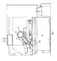
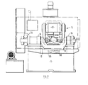
- the machine comprises a bed 6 upon which grinding mechanism 8 is mounted.
- the grinding mechanism 8 comprises a drive motor 10, and a belt drive 12 for each of the two spaced grinding wheels 14,which are preferably from 75mm to 115mm in diameter.
- the grinding mechanism is mounted for horizontal sliding movement across the bed 6 between a retracted position (shown in dotted lines in Figure 4) and an advanced position, as shown in full lines in the drawings.
- journal bearings 16 which have a common longitudinal axis LA3 which lies in a horizontal plane in which the axes of rotation of the grinding wheels 14 also lie.
- a cranked arm 18 Extending between journal bearings 16, for rocking movement about the common axis thereof, is a cranked arm 18.
- One end portion of the arm 18 is connected to driving mechanism 20, adapted to effect a controlled rotation of the arm 18 about the common axis of the bearings 16.
- each of said axes passing through the point of interception of the common axes LA3 of the journal bearings 16, and the line of movement of the centre of rotation of one of the grinding wheels 14 between its retracted and advanced positions.
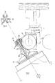
- Each of the spindle mechanisms 22 is carried by an indexing mechanism 66 (not shown in detail), adapted under automatic or operator control to rotate its associated spindle mechanism 22 through a portion of a revolution.
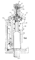
- Each spindle mechanism 22 comprises a clamping device 24, adapted to clamp a workpiece in a position in which the longitudinal axis LA2 of the workpiece is coincident with the longitudinal axis of the spindle mechanism, and in which the centre of curvature C of the ball tracks to be machined is coincident with the point of interception of the common axes of the bearings 16, and the line of travel of the centre of the associated grinding wheel 14.
- the clamping mechanism comprises a workpiece supporting device 26, upon which the workpiece may be positioned, and a clamping device 28 adapted firmly to clamp the workpiece against the supporting device.
- the workpiece supporting device 26 comprises a base portion 29, to an upper surface of which a support member 30 is secured, said support member 30 providing a flat, annular base surface 32 which lies in a plane disposed around, and at right angles to, the longitudinal axis of the clamping mechanism, and a plurality of resilient fingers 34 extending radially outwardly- (seew Figure 5), each finger providing a curved, inwardly facing surface 35 (see also Figure 7).
- the surfaces 35 lie in a cone, and are arranged to be engaged tangentially by the outer surface 82 of the joint member, when clamped in position.
- the clamping device 28 comprises a clamping member afforded by a split collet 38, having clamping portions 40 which are capable of limited radial outward movement from the position shown in Figure 7.
- the collet 38 is mounted for limited movement along the longitudinal axis of the clamping mechanism, an inner end of the collet being carried by a mounting member 42, which is urged into an upper position by compression springs 44 (see Figure 6).
- the base portion 29 of the workpiece supporting device 26 is secured to a cylindrical sleeve 60, which is secured in position against axial movement but which is rotatable about the longitudinal axis on bearings carried by an outer casing 64.
- the clamping mechanism comprises an operating mechanism 46, which comprises an operating member 48 which extends axially through the collet 38. At an outer end portion, the operating member is provided with a head 50, beneath which there is provided an enlarged portion 53 which provides a frusto-conical outer surface 51, a flat annular surface 52 being provided beneath the head. At its inner end, the operating member 48 is secured to an upper end of a hollow piston-like element 56, which is urged downwardly ( Figure 6) by a powerful spring 58.
- the machine also comprises twin dresser units 78, adapted to retain the grinding surface of the two grinding wheels in a condition with a desired surface profile.
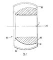
- the machine which is the preferred embodiment of this invention is specifically adapted for use in the machining of ball tracks 80 in the outer surface 82 of the inner joint member 84 os a constant velocity universal joint of the kind illustrated in Figure 1 of the drawings.
- the ball tracks 80 (of which there are six)are uniformely spaced around the circumference of the inner member, and are curved in the longitudinal sense about an axis which is situated on the longitudinal axis of the joint member.
- the ball tracks 80 are of "gothic arch" cross-section, so that contact between the ball tracks and the torque transmitting balls is linear. It will however be appreciated that the ball tracks 80 may of any desired cross-section.
- a workpiece for an inner joint member 84 is mounted on the workpiece support member 30 of each of the spindle mechanisms 22, and is clamped thereon, in a position in which the longitudinal axis LA2 of the workpiece coincident with the longitudinal axis LA1 of the spindle mechanism in each case.
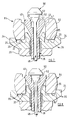
- each spindle mechanism by firstly admitting fluid under pressure beneath the hollow piston-like element 56, to cause said element to move upwardly against the action of the compression spring 58, so that the enlarged portion 53 of the operating member 48 moves out of the collet 38, allowing the clamping portions 40 of the collet to move inwardly, by virtue of the resilience of the collet, as is shown in Figure 7.
- the diameter of the outer edge 41 of the collet is in this position slightly less than the inner diameter of the joint member 84, allowing the joint member to be placed on the support device 26, into a position in which the outer surface 82 of the joint member seats against the curved surfaces 35 of the fingers 34. In this position, the base 85 of the joint member will be separated a slight distance from the base surface 32 of the support device 26.
- the joint member may be located and retained in a desired position, to an accuracy of 0.005 or better.
- the grinding mechanism With the arm 18, and consequently the spindle mechanisms 22 and indexing mechanisms 66,in a first position (shown in Figure 4) the grinding mechanism is advanced, from its retracted position into a contact position in which the grinding wheels which are rotating at a suitable speed, engage the workpiece.
- the driving mechanism 20 is then operated to rotate the arm 18 about the common axis LA3 of the journal bearings 16 through an angualar rotation of 80°, and is then returned, causing the grinding wheels 14 each to traverse its associated workpiece.
- the grinding wheels are then advanced incrementally, and the 80° oscillation is repeated, until the grinding wheels reach their fully advanced positions, when the ball tracks will be machined to the required depth.
- the arm 18, and consequently the workpiece, spindle mechanisms 22 and indexing mechanisms 36 are moved through a further 30° to disengage the workpieces from the grinding wheels, and the grinding mechanism is retracted to its positon slightly rearwardly of its contact position.
- the indexing mechanism 66 is then operated to rotate both of the spindle mechanisms through 60°, involving a rotation of the sleeves 60 and thus the element 56, and the clamping mechanism 24 about their respective longitudinal axes LA1, causing further surface portions of the workpieces to be presented to the grinding wheels 14,preparatory to the grinding of further ball tracks in the two workpieces.
- the support arm 18 is again oscillated about is pivotal axis, and the grinding mechanism is again incrementally advanced from its contact position to its fully advanced position, in the machining of a further ball track in each workpiece, at which point the workpieces are disengaged from the grinding wheels as before.
- the grinding mechanism On completion of machining of all six ball tracks in the workpiece, and on completion of full oscillation of the support arm to carry the workpieces from engagement with the grinding wheels, the grinding mechanism is moved to its fully retracted position to provide sufficient clearance to allow the workpieces to be removed from the spindle heads, to be replaced by fresh workpieces. This is accomplished by the application of fluid under pressure to the element 56, causing it to advance against the action of the compression spring 58. Initially both the operating member 48 and the collet 38 move upwardly from within the central bore of the joint member 84, whereupon the enlarged portion 53 of the operating member 48 moves from within the clamping portions 40 of the collet 38 allowing said clamping portions 48 to move slightly together under the resilience of the collet. The machined joint member 84 may then be removed from the supporting device, and replaced by a fresh blank to be operated on by the machine.
- the indexing mechanism which causes rotation of the workpiece blank through a desired portion of a revolution between each machining operation, may be constructed sturdily and robustly.
- a joint member may be secured in position with an accuracy which has heretofore only been achieved with considerable difficulty.
- the smallness of the grinding wheels 14 allows the spindle mechanisms 22 not only to hold their workpieces securely during the machining operation,but additionally allows precision indexing mechanism to be utilised. In this manner, the angular spacing of the ball tracks 40 of the inner joint member may be provided to an accuracy which has hitherto been difficult to obtain in automatically operating, volume-production machinery.
- the accuracy of the provision of the ball tracks of the inner member allows the universal joint to be assembled with notable lack of relative movement between the. inner and outer members, without the provision of undue clamping forces. In this manner, the universal joint may operate more smoothly,more silently, with less frictional forces acting on the torque transmitting balls during articulation of the joint, which affords the universal joint with a longer life.
- the clamping mechanism of the machine which is the preferred embodiment of this invention is particularly adept in the securing in position of the inner member of a universal joint of the kind specified during the performance of the described grinding operation
- the clamping mechanism may be utilised for the securement of the joint member in position during other machining operations, and may be used to advantage in the securing in position of similar articles, where analogous problems arise.
Landscapes
- Engineering & Computer Science (AREA)
- Mechanical Engineering (AREA)
- Grinding And Polishing Of Tertiary Curved Surfaces And Surfaces With Complex Shapes (AREA)
- Constituent Portions Of Griding Lathes, Driving, Sensing And Control (AREA)
Applications Claiming Priority (2)
| Application Number | Priority Date | Filing Date | Title |
|---|---|---|---|
| GB8007400 | 1980-03-05 | ||
| GB8007400 | 1980-03-05 |
Publications (2)
| Publication Number | Publication Date |
|---|---|
| EP0035267A2 true EP0035267A2 (de) | 1981-09-09 |
| EP0035267A3 EP0035267A3 (de) | 1982-03-17 |
Family
ID=10511868
Family Applications (1)
| Application Number | Title | Priority Date | Filing Date |
|---|---|---|---|
| EP81101479A Withdrawn EP0035267A3 (de) | 1980-03-05 | 1981-03-02 | Schleifverfahren, Schleifmaschine und Mechanismus zum Einspannen eines Werkstückes |
Country Status (2)
| Country | Link |
|---|---|
| EP (1) | EP0035267A3 (de) |
| GB (1) | GB2070990B (de) |
Cited By (7)
| Publication number | Priority date | Publication date | Assignee | Title |
|---|---|---|---|---|
| EP0316742A3 (en) * | 1987-11-19 | 1990-10-10 | Siegfried Rast | Machine for finishing work pieces |
| EP0576520A4 (en) * | 1991-02-20 | 1995-12-20 | Constant Velocity Systems Inc | Method of and machine for grinding a workpiece |
| FR2736856A1 (fr) * | 1995-03-23 | 1997-01-24 | Sarl Ermmi | Machine pour la rectification de surfaces de guidage pratiquees dans une cavite |
| CN106976006A (zh) * | 2017-04-25 | 2017-07-25 | 上海众源燃油分配器制造有限公司 | 一种用于高压油管球形接头表面抛光的装置 |
| CN114043377A (zh) * | 2022-01-13 | 2022-02-15 | 江苏三尔汽车部件有限公司 | 一种汽车减震器加工用抛光装置 |
| CN114473740A (zh) * | 2021-12-20 | 2022-05-13 | 浙江信胜科技股份有限公司 | 绣花机珠子绣用钢丝的槽口高精度加工机 |
| CN119871155A (zh) * | 2025-03-27 | 2025-04-25 | 杭州腾励传动科技股份有限公司 | 一种内星轮球道打磨装置 |
Families Citing this family (1)
| Publication number | Priority date | Publication date | Assignee | Title |
|---|---|---|---|---|
| CN103934753B (zh) * | 2014-04-22 | 2016-02-17 | 成都海凌达机械有限公司 | 翻新轮胎打磨夹持装置 |
Family Cites Families (10)
| Publication number | Priority date | Publication date | Assignee | Title |
|---|---|---|---|---|
| US2289683A (en) * | 1941-09-15 | 1942-07-14 | Gear Grinding Mach Co | Jig |
| US2972935A (en) * | 1954-05-24 | 1961-02-28 | Bendix Corp | Ball race cutting machine |
| GB1020443A (en) * | 1961-09-21 | 1966-02-16 | Birfield Eng Ltd | Improvements in or relating to machine tools |
| DE1270928B (de) * | 1961-09-21 | 1968-06-20 | Birfield Eng Ltd | Vorrichtung zum Fraesen von Rillen in Werkstuecke |
| GB1068479A (en) * | 1964-08-04 | 1967-05-10 | Birfield Eng Ltd | Improvements in or relating to universal joints |
| US3517939A (en) * | 1968-03-05 | 1970-06-30 | Gleason Works | Work holder and radially expansible collet therefor |
| JPS5220625B1 (de) * | 1968-06-27 | 1977-06-04 | ||
| DE2346111C3 (de) * | 1973-09-13 | 1978-06-08 | Heinz Ditzel | An einer Schleifmaschine angeordnete Aufspann- und Teileinrichtung für Kugelnaben oder dergleichen zum Schleifen ihrer Zylinderringnuten |
| FR2421024A1 (fr) * | 1978-03-31 | 1979-10-26 | Rouchaud Et Lamassiaude Ets | Machine a fraiser des rainures notamment dans les noix de cardans |
| JPS55163324A (en) * | 1979-06-01 | 1980-12-19 | Toyota Motor Corp | Constant velocity ball joint |
-
1981
- 1981-03-02 GB GB8106522A patent/GB2070990B/en not_active Expired
- 1981-03-02 EP EP81101479A patent/EP0035267A3/de not_active Withdrawn
Cited By (7)
| Publication number | Priority date | Publication date | Assignee | Title |
|---|---|---|---|---|
| EP0316742A3 (en) * | 1987-11-19 | 1990-10-10 | Siegfried Rast | Machine for finishing work pieces |
| EP0576520A4 (en) * | 1991-02-20 | 1995-12-20 | Constant Velocity Systems Inc | Method of and machine for grinding a workpiece |
| FR2736856A1 (fr) * | 1995-03-23 | 1997-01-24 | Sarl Ermmi | Machine pour la rectification de surfaces de guidage pratiquees dans une cavite |
| CN106976006A (zh) * | 2017-04-25 | 2017-07-25 | 上海众源燃油分配器制造有限公司 | 一种用于高压油管球形接头表面抛光的装置 |
| CN114473740A (zh) * | 2021-12-20 | 2022-05-13 | 浙江信胜科技股份有限公司 | 绣花机珠子绣用钢丝的槽口高精度加工机 |
| CN114043377A (zh) * | 2022-01-13 | 2022-02-15 | 江苏三尔汽车部件有限公司 | 一种汽车减震器加工用抛光装置 |
| CN119871155A (zh) * | 2025-03-27 | 2025-04-25 | 杭州腾励传动科技股份有限公司 | 一种内星轮球道打磨装置 |
Also Published As
| Publication number | Publication date |
|---|---|
| GB2070990B (en) | 1983-03-16 |
| GB2070990A (en) | 1981-09-16 |
| EP0035267A3 (de) | 1982-03-17 |
Similar Documents
| Publication | Publication Date | Title |
|---|---|---|
| CN101337329B (zh) | 用于加工围绕工件轴线旋转的工件的方法和装置 | |
| US4574448A (en) | Apparatus for fastening machine element to a shaft | |
| US4593444A (en) | Machine for manufacturing universal joints | |
| EP0035267A2 (de) | Schleifverfahren, Schleifmaschine und Mechanismus zum Einspannen eines Werkstückes | |
| JP2647080B2 (ja) | ポータブル旋盤の軸受装置 | |
| SU928998A3 (ru) | Устройство дл автоматической смены инструментов на металлорежущем станке | |
| JP3749923B2 (ja) | 自動車用ホイールの研削加工装置 | |
| JPS61197111A (ja) | 孔縁部用バリ取り工具 | |
| JP3204205B2 (ja) | 等速自在継手の加工治具 | |
| JPS6165772A (ja) | ドレツシング装置 | |
| CN109531234A (zh) | 转盘式机械加工设备 | |
| JPH1058305A (ja) | 砥石ヘッド | |
| JPH01112007A (ja) | 連結装置 | |
| JPS6049535B2 (ja) | ワ−ク供給装置 | |
| CN211388274U (zh) | 一种周面开孔工件的珩磨工装 | |
| JPH0253180B2 (de) | ||
| SU1140936A1 (ru) | Устройство дл двусторонней обработки оптических деталей с криволинейными поверхност ми | |
| JPS625743B2 (de) | ||
| JPH078084Y2 (ja) | 等速ジョイント内輪のチャック装置 | |
| JP3012777B2 (ja) | 外輪部材の芯出し保持装置 | |
| SU848163A1 (ru) | Многоместный патрон | |
| JPH0347761Y2 (de) | ||
| JPH0144297Y2 (de) | ||
| US4330966A (en) | Groove grinding fixture | |
| JPS6122723Y2 (de) |
Legal Events
| Date | Code | Title | Description |
|---|---|---|---|
| PUAI | Public reference made under article 153(3) epc to a published international application that has entered the european phase |
Free format text: ORIGINAL CODE: 0009012 |
|
| AK | Designated contracting states |
Designated state(s): AT DE FR GB IT SE |
|
| PUAL | Search report despatched |
Free format text: ORIGINAL CODE: 0009013 |
|
| AK | Designated contracting states |
Designated state(s): AT DE FR GB IT SE |
|
| STAA | Information on the status of an ep patent application or granted ep patent |
Free format text: STATUS: THE APPLICATION IS DEEMED TO BE WITHDRAWN |
|
| 18D | Application deemed to be withdrawn |
Effective date: 19830223 |
|
| RIN1 | Information on inventor provided before grant (corrected) |
Inventor name: MADDAFORD, JOHN Inventor name: LEE, GEOFFREY FOSTER |