EP0035367B1 - Automatisches Bündelwerkzeug - Google Patents
Automatisches Bündelwerkzeug Download PDFInfo
- Publication number
- EP0035367B1 EP0035367B1 EP81300791A EP81300791A EP0035367B1 EP 0035367 B1 EP0035367 B1 EP 0035367B1 EP 81300791 A EP81300791 A EP 81300791A EP 81300791 A EP81300791 A EP 81300791A EP 0035367 B1 EP0035367 B1 EP 0035367B1
- Authority
- EP
- European Patent Office
- Prior art keywords
- ties
- tail
- tool
- tie
- successive
- Prior art date
- Legal status (The legal status is an assumption and is not a legal conclusion. Google has not performed a legal analysis and makes no representation as to the accuracy of the status listed.)
- Expired
Links
- 239000002699 waste material Substances 0.000 claims description 6
- 229920002457 flexible plastic Polymers 0.000 abstract 1
- 238000010304 firing Methods 0.000 description 5
- MFOUDYKPLGXPGO-UHFFFAOYSA-N propachlor Chemical compound ClCC(=O)N(C(C)C)C1=CC=CC=C1 MFOUDYKPLGXPGO-UHFFFAOYSA-N 0.000 description 5
- 238000010276 construction Methods 0.000 description 3
- 230000000994 depressogenic effect Effects 0.000 description 2
- 238000000465 moulding Methods 0.000 description 2
- 230000000717 retained effect Effects 0.000 description 2
- 241000519996 Teucrium chamaedrys Species 0.000 description 1
- 230000006835 compression Effects 0.000 description 1
- 238000007906 compression Methods 0.000 description 1
- 238000006073 displacement reaction Methods 0.000 description 1
- 238000002347 injection Methods 0.000 description 1
- 239000007924 injection Substances 0.000 description 1
- 238000001746 injection moulding Methods 0.000 description 1
- 239000002991 molded plastic Substances 0.000 description 1
- 238000004806 packaging method and process Methods 0.000 description 1
- 238000012856 packing Methods 0.000 description 1
- 238000000926 separation method Methods 0.000 description 1
- 230000001360 synchronised effect Effects 0.000 description 1
- 238000003466 welding Methods 0.000 description 1
Images




Classifications
-
- B—PERFORMING OPERATIONS; TRANSPORTING
- B65—CONVEYING; PACKING; STORING; HANDLING THIN OR FILAMENTARY MATERIAL
- B65B—MACHINES, APPARATUS OR DEVICES FOR, OR METHODS OF, PACKAGING ARTICLES OR MATERIALS; UNPACKING
- B65B13/00—Bundling articles
- B65B13/02—Applying and securing binding material around articles or groups of articles, e.g. using strings, wires, strips, bands or tapes
- B65B13/025—Hand-held tools
- B65B13/027—Hand-held tools for applying straps having preformed connecting means, e.g. cable ties
-
- B—PERFORMING OPERATIONS; TRANSPORTING
- B65—CONVEYING; PACKING; STORING; HANDLING THIN OR FILAMENTARY MATERIAL
- B65B—MACHINES, APPARATUS OR DEVICES FOR, OR METHODS OF, PACKAGING ARTICLES OR MATERIALS; UNPACKING
- B65B13/00—Bundling articles
- B65B13/18—Details of, or auxiliary devices used in, bundling machines or bundling tools
- B65B13/185—Details of tools
- B65B13/187—Motor means
- B65B13/188—Motor means pneumatic or hydraulic
-
- B—PERFORMING OPERATIONS; TRANSPORTING
- B65—CONVEYING; PACKING; STORING; HANDLING THIN OR FILAMENTARY MATERIAL
- B65D—CONTAINERS FOR STORAGE OR TRANSPORT OF ARTICLES OR MATERIALS, e.g. BAGS, BARRELS, BOTTLES, BOXES, CANS, CARTONS, CRATES, DRUMS, JARS, TANKS, HOPPERS, FORWARDING CONTAINERS; ACCESSORIES, CLOSURES, OR FITTINGS THEREFOR; PACKAGING ELEMENTS; PACKAGES
- B65D63/00—Flexible elongated elements, e.g. straps, for bundling or supporting articles
- B65D63/10—Non-metallic straps, tapes, or bands; Filamentary elements, e.g. strings, threads or wires; Joints between ends thereof
- B65D63/1018—Joints produced by application of integral securing members, e.g. buckles, wedges, tongue and slot, locking head and teeth or the like
- B65D63/1027—Joints produced by application of integral securing members, e.g. buckles, wedges, tongue and slot, locking head and teeth or the like the integral securing member being formed as a female and male locking member, e.g. locking head and locking teeth, or the like
- B65D63/1063—Joints produced by application of integral securing members, e.g. buckles, wedges, tongue and slot, locking head and teeth or the like the integral securing member being formed as a female and male locking member, e.g. locking head and locking teeth, or the like the female locking member being provided with at least one plastic barb
- B65D63/1072—Joints produced by application of integral securing members, e.g. buckles, wedges, tongue and slot, locking head and teeth or the like the integral securing member being formed as a female and male locking member, e.g. locking head and locking teeth, or the like the female locking member being provided with at least one plastic barb the barb having a plurality of serrations
Definitions
- This invention relates to a tool for automatically applying ties.
- DE-A-2723651 discloses a tool for automatically applying around an elongate roll or bundle, a flexible tie having a flat tail and an apertured head at one end of the tail, the tool feeding from a supply of said ties and the tool comprising an indexing arrangement for indexing each of successive ties into a tail-forward, ready position within the tool, a mechanism for driving tail-first from the tool the tie which is in the tail-forward, ready position, a guiding arrangement at the forward end of the tool for guiding the tie tail around the bundle to be tied as the tie is driven from the tool and arranged so that the free end of the tail passes through the apertured head to interlock therein, a mechanism for engaging the free end of the tail (once passed through said apertured head) and driving it lengthwise of itself to tension the tie around the bundle being tied, a knife for cutting the tail behind the head and a tension-sensing device for actuating said knife when a predetermined tension is reached.
- the ties are contained in a cartridge into which they must be packaged one-by-one in presumably a manual operation: firstly moreover, the ties must be separated individually after they are formed by injection moulding. Thus, provision of the supply of ties for the tool is time consuming and complicated.
- our invention is characterised in that the supply of ties for the tool is in the form of a belt in which the ties are disposed side-by-side with each other with their tails disposed flat in a common plane and with adjacent ties integrally interconnected at or adjacent both their heads and tail free ends, in that the indexing arrangement of the tool engages the successive ties along their lengths to advance the belt so as to step each of the successive ties laterally of itself (in the plane of its flat tail) into the tail-forward, ready position within the tool, in that the tool comprises a cutting mechanism for separating the successive ties from their neighbouring ties at or adjacent both their heads and tail free ends, and in that means are provided for expelling as waste bridging pieces which serve to integrally interconnect the adjacent ties at least adjacent their tail free ends.
- a plurality of ties can be directly moulded side-by-side, integrally interconnected: successive sets of such ties can be interconnected (as by welding) to form a belt of considerable length.
- successive sets of such ties can be interconnected (as by welding) to form a belt of considerable length.
- the indexing arrangement serves to advance the belt so that each tie is stepped laterally of itself (in the plane of its flat tail) into the ready position within the tool; by contrast in the tool of DE-A-2723651, the ties are stacked with the flat tail of one tie disposed flat upon the flat tail of the preceding tie, and each tie is stepped into the ready position by displacement of that tie in the direction perpendicular to its flat tail.
- the tool of DE-A-2723651 is not capable of feeding from the belt of ties proposed by our invention and in any event does not incorporate any cutting mechanism for cutting each of the successive ties from the belt.
- DE-A-2 837 101 relates to the field of tags and describes a tool for applying such tags. This is a distinctly different field from the tie field of the present invention and the tags are of considerably less sophistication than the ties and work in accordance with completely different principles, necessitating only a relatively simple and straightforward form of application tool.
- the tags serve as temporary fastenings which do not have to resist any significant force tending to separate the elements fastened together: the ties could not be manufactured, to their required standard of precision, on continuous moulding apparatus as shown for the tags in Figure 10-12 of DE-A-2 837 101.
- the tag a simple and unsophisticated product, so too is the tool for applying the tag: it comprises essentially a slotted piercing needle and one side member of the tag is engaged into the rear end of this needle, with a cross-link of the tag projecting out of the slot in the needle; then the one side member of the tag is simply pushed along the needle and through the elements to be fastened (which have been pierced by the needle).
- the tag admits readily to a bandolier principle, because they can be moulded easily with the side member of successive tags joined end-to-end and so that they can be separated without any waste pieces having to be disposed of.
- the advancing direction of the belt of tags is essentially the same direction as the tag is required to advance when being applied to the elements to be fastened: there is no requirement to position each successive tag accurately (by step-advancing the belt) prior to driving the tag out of the tool, because the tag is driven out of the tool in the same direction as the belt of tags is advanced.
- DE-A-2 837 101 is of no assistance to the tie applying field: in particular there is no apparent manner in which the teachings of DE-A-2 837 101 can be applied to the tool of DE-A-2 723 651 to develop the latter tool.
- the indexing arrangement comprises a rotary drum rotatable about an axis parallel to the tie in the ready position, the rotary drum having longitudinal grooves in its periphery, which grooves accommodate successive ties of the belt to be advanced by stepped rotation of the drum and which grooves support and engage the ties substantially along the lengths of those ties. Indexing is facilitated in a simple and reliable manner.
- the tie gun illustrated in Figure 1 is particularly adapted for binding cables together with flexible ties, the fastenings of which have a low profile when secured around the cable bundle. Operation of the gun is controlled by a pneumatic cylinder and the various stages in the operating cycle are indexed to the stroke of the piston of the cylinder.
- the general sequence of its operation is outlined along with a brief description of the tie and the feed mechanism. Then the operating sequence is explained in more detail with reference to the drawings, and this is followed by a detailed description of the construction of the various units of the gun which perform specific functions which are referred to in the operating sequence, and also by a more detailed description of the flexible ties used in the gun.
- the operating sequence of the gun is governed by the piston of the pneumatic control cylinder which is linked to a ram so that during the inward and outward strokes of the piston, which respectively produce forward and rearward strokes of the ram, flanges on the ram engage with and activate other parts of the mechanism.
- the piston is activated to move inwardly by depression of a trigger, whereupon a guide loop is closed about the bundle of cables which are to be bound and the tip of a flexible tie is pushed forward so that it passes around the cable via the guide loop and is threaded through a fastener in the form of an apertured head on the other end of the tie.
- a fastener in the form of an apertured head on the other end of the tie.
- the feed mechanism by which the ties are advanced includes a cylindrical drum with longitudinal recesses which accommodate the tails of the ties as they are fed laterally into the gun from one side of the drum.
- the ties are advanced by rotation of the drum during the latter part of each outward stroke of the piston which brings successive ties to the topmost position ready for subsequent firing.
- the ties are joined together by bridging pieces to form a belt. Once a tie is in the firing position it is cut free from its bridging pieces by a cropping mechanism.
- a tie may be employed in which the tail threads through a longitudinal aperture in the buckle so that the threaded portion lies along the portion of the tie adjacent to the buckle rather than projecting perpendicular to it.
- the buckle needs to be rotated through 180° (compared with when the tie is laid flat) to receive the tail which has been passed around the bundle of cables. Therefore, in addition to advancing successive ties to the firing position, the feed mechanism of the gun also rotates the buckle to the correct orientation for receiving the tail.
- the tie gun is shown generally as 1, and has a spring return trigger 2.
- a guide loop 3 is provided at the end of barrel 4 of the gun, and can be closed about a suitable bundle of cables adjacent to which the end of the barrel 4 has been placed.
- Trigger 2 is provided with an inclined surface 5 which abuts an inclined surface on the spool 6 of a valve 7 so that upon a depression of the trigger the spool 6 is lifted and air is provided to one end of a pneumatic cylinder 8 which, as may be seen from Figures 2 and 3, is disposed in the barrel 4 of the gun with its piston rod free to extend into rear portion 9 of the gun 1.
- Spool 6 is held in its lifted position by detent 10 and the extended piston of the pneumatic cylinder retracts moving a ram 11, which is connected to the piston, to the left as viewed.
- Ram 11 is provided with a flange 12 at its end remote from the barrel which abuts a flange 13 on a biased rod 14, so that as flange 13 moves leftwards it permits rod 14 to move left under the influence of spring 15, which closes guide loop 3.
- the barrel end of ram 11 acts as a pusher for a tie 16, whereby said ram may more generally be referred to as a push rod.
- a scrap release trigger 26 which is spring loaded upwards but depressed during the passage of the ram rod 11 over it, is then released as it is cleared by the end of ram 11, and this trigger then engages clamp 22 so that the tail is released, the tail being impelled into scrap bottle 27 partly under its own momentum and partly by pneumatic ejection.
- a projection 28 on ram rod 11 engages a bell crank 29 to advance a feed ratchet 30 which rotates drum 31 and aligns a new tie with the end of the ram 11 ready for the next cycle.
- Figure 4 shows the feed ratchet 30 and bell crank 29 in detail. Bell crank 29 is sprung so that it can move to the next ratchet position, when it is released on the inward stroke of the piston, ready to rotate the drum 31 during the subsequent outward stroke.
- Precise positioning of the drum may be achieved by a rotation detent in which a sprung member indexes with notches in the drum once it has been rotated by the bell crank and ratchet. Whilst the outward stroke of the piston continues further, a flange on the ram rod 11 engages with a forked lever 32, the other end of which engages a flange 33 on cut-off rod 24 to ensure that the cut-off unit is properly reset, and finally, flange 12 of ram rod 11 pushes flange 13 to the right which opens the guide loop 3 and releases the bound cable.
- Figure 5 shows the construction of a suitable low profile buckle with the threaded portion of the tail lying parallel to the end of the tie adjoining the buckle.
- the ties which may be made of injection moulded plastics, are fully described hereinafter with reference to Figures 12 to 18.
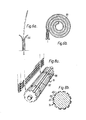
- Figures 6a and 6b show two alternative forms of support for a belt of ties, in the simplest case one or more pairs of curved supports 34 are used, or, if it is undesirable to have the belt left waving, a magazine 35 in which the belt can be coiled is used.
- the belt of ties is fed into the gun 1 via a slot 36 which can be seen in the front perspective view of the gun in Figure 7.
- the belt passes around drum 31 which is recessed as shown in Figure 8 with longitudinal grooves 37 for the ties and circumferential grooves 38 for the bridging pieces between the ties.
- Longitudinal grooves 37 are deeper than circumferential grooves 38 so that the ties are supported on the drum 31, by the bridging pieces, above the base of the longitudinal grooves 37.
- the longitudinal grooves may also serve, at one end, as the notches into which the sprung member of the rotation detent indexes.
- FIG. 9 schematically shows the action of crops 39; the action is synchronised to take place immediately after the tie has been rotated into position by feed ratchet 30, both the feed ratchet 30 and the crops 39-being activated by projection 28.
- the scrap bridging pieces drop into a waste chute 41 and are exhausted into waste bottle 27.
- Drum 31 is provided with cutaway apertures 43 in the circumferential groove 38, each of these being arranged so as to be covered by the bridging pieces of the belt of ties (see Figure 8) when there is a tie in the respective preceding longitudinal slot 37.
- An airline has an open end located such that after the last tie of a belt of ties feeding into the gun has been engaged, and the drum is rotated to the next position where it would otherwise have engaged the next tie, air from airline passes through the uncovered aperture 43 and causes a whistle indicating that a new belt of ties is required.
- the cut-off unit 23 is shown in Figure 1; for clarity it is illustrated displaced rearward from its correct position whilst Figure 2 shows the cut-off unit correctly positioned.
- pressure in the pneumatic cylinder 8 rises in proportion to the tension in the tie.
- the cut-off unit is therefore responsive to the pressure in the pneumatic cylinder and can be adjusted such that the tightened tie is cut-off at a predetermined tie tension.
- a line 45 connects the cut-off unit to the pneumatic cylinder, so that the pressure applied to the left (as viewed) of a poppet 46 is equal to that driving the piston of the pneumatic cylinder 8.
- the poppet 46 is held in position by a spring 47, until the applied air pressure exceeds the pressure exerted by the spring 47, whereupon the poppet is unseated and moves to the right moving cut-off rod 24 and actuating knife 25. Release of the tie tension once the tail has been cut, and the drop in air pressure in the cut-off unit due to sudden expansion of air when the poppet is unseated, enables the poppet 46 to be pushed left again by spring 47. Meanwhile the piston of pneumatic cylinder 8, also relieved of the tension of the tie, completes its stroke and lever 32 engages flange 33 and ensures that the poppet 46 is reseated in its original position. Different tie tensions may be obtained by adjusting knob 48 which changes the compression in spring 47.
- the buckle 17 has a longitudinal aperture 49 through which the tail can be threaded so that ratchet serrations 50 on one surface of the tail engage with a pawl 51, which prevents thetail from being pulled back out. of the aperture 49 but enables it to be advanced through to tighten the loop 52 formed by the tail.
- a slot 53 is provided beneath pawl 51 which enables it to be resiliently depressed by the serrations 50 for ease of advancement of the tail through the aperture 49.
- Figure 14 shows a bundle of cables bound by flexible ties illustrating the low profile fastening achieved by the flexible ties used in the tie gun.
- a low profile tie of this type may, as well as being visually appealing, be particularly advantageous for example when the bound cables are to be inserted through restricted apertures, or into confined spaces, such as may occur when fitting wired looms.
- the tie is illustrated with serrations on the tail of the tie such that when the tie is threaded the serrations are on the inside of the loop.
- the serrations may alternatively be formed so that they are on the outside of the loop, and in this case the pawl is formed extending down from the upper surface (as viewed) of the buckle 17.
- the ties may be connected by integrally moulded bridging pieces as shown in Figure 15a. However in order that the fasteners may be bent outwards by the voluted surface 42 without requiring previous separation, the ties are preferably fabricated, as shown in Figure 15b, with the heads separate and the two bridging pieces 54 between the tails of adjacent ties. To ease the tooling requirements the belt of ties may be moulded with the tail bent through 90° near the buckle 17, as is shown in section in Figure 16.
- bent belts can be pressed flat for packing, and when used the preformed bend facilitates turning the buckle into the position shown in Figure 16b for threading by the end of tail.
- individually moulded belts may be connected into a continuous longer belt as shown in Figure 17.
- joints 55 between the individually moulded belts should be made as smooth as possible.
- Figures 18a to 18e show a modified form of low profile tie.
- This tie is illustrated with serrations which will be disposed on the outside of the loop when the tie is threaded.
- the serrations engage with similarly profile teeth 56 extending from the upper surface of the buckle.
- Channels 57 are provided in the buckle which accommodate ridges 58 along the edges of the tail.
- the gun mechanism may be housed in a die- cast body, one half acting as a chassis onto which the component parts of the mechanism may be mounted, and the other half acting as a cover.
- a suitable type of pneumatic cylinder is a Martonair Midget M/6010 which has a 10 mm bore, 4 mm diameter rod and 130 mm stroke; a suitable type of valve is a Martonair M/1555/1.
Landscapes
- Engineering & Computer Science (AREA)
- Mechanical Engineering (AREA)
- Basic Packing Technique (AREA)
- Package Frames And Binding Bands (AREA)
- Shovels (AREA)
- Clamps And Clips (AREA)
Claims (4)
Priority Applications (1)
| Application Number | Priority Date | Filing Date | Title |
|---|---|---|---|
| AT81300791T ATE22856T1 (de) | 1980-02-27 | 1981-02-26 | Automatisches buendelwerkzeug. |
Applications Claiming Priority (2)
| Application Number | Priority Date | Filing Date | Title |
|---|---|---|---|
| GB8006529 | 1980-02-27 | ||
| GB8006529 | 1980-02-27 |
Publications (2)
| Publication Number | Publication Date |
|---|---|
| EP0035367A1 EP0035367A1 (de) | 1981-09-09 |
| EP0035367B1 true EP0035367B1 (de) | 1986-10-15 |
Family
ID=10511702
Family Applications (2)
| Application Number | Title | Priority Date | Filing Date |
|---|---|---|---|
| EP81300791A Expired EP0035367B1 (de) | 1980-02-27 | 1981-02-26 | Automatisches Bündelwerkzeug |
| EP81300792A Withdrawn EP0035368A1 (de) | 1980-02-27 | 1981-02-26 | Biegsame Gurte |
Family Applications After (1)
| Application Number | Title | Priority Date | Filing Date |
|---|---|---|---|
| EP81300792A Withdrawn EP0035368A1 (de) | 1980-02-27 | 1981-02-26 | Biegsame Gurte |
Country Status (5)
| Country | Link |
|---|---|
| EP (2) | EP0035367B1 (de) |
| JP (2) | JPS56123212A (de) |
| AT (1) | ATE22856T1 (de) |
| CA (1) | CA1154666A (de) |
| DE (1) | DE3175471D1 (de) |
Cited By (1)
| Publication number | Priority date | Publication date | Assignee | Title |
|---|---|---|---|---|
| USD473773S1 (en) | 2002-10-29 | 2003-04-29 | Panduit Corp. | Cable tie installation tool |
Families Citing this family (19)
| Publication number | Priority date | Publication date | Assignee | Title |
|---|---|---|---|---|
| US4498506A (en) * | 1982-11-24 | 1985-02-12 | Panduit Corp. | Tool for the automatic installation of discrete cable ties provided on a continuous ribbon of cable ties |
| JPS59142931A (ja) * | 1983-01-31 | 1984-08-16 | 株式会社 日本バノツク | 係止紐の連結方法及びその装置 |
| JPS59136008U (ja) * | 1983-03-01 | 1984-09-11 | 興和特殊工業株式会社 | 簡易結束具 |
| JPH0229286Y2 (de) * | 1985-10-15 | 1990-08-07 | ||
| IT1227770B (it) * | 1987-07-01 | 1991-05-06 | Rta Italiana Spa | Procedimento e attrezzatura per la legatura automatica di fasci di conduttori, per mezzo di una banda continua. |
| FR2619551B1 (fr) * | 1987-08-20 | 1990-01-19 | Dufrene Alain | Poignee rapportee sur emballage, son procede de fabrication et les moyens pour la mise en oeuvre de ce procede |
| JPH0285574U (de) * | 1988-12-23 | 1990-07-05 | ||
| GB8907143D0 (en) * | 1989-03-30 | 1989-05-10 | Bowthorpe Hellermann Ltd | Automatic tie gun |
| DE29504940U1 (de) * | 1995-03-23 | 1996-07-18 | Paul Hellermann GmbH, 25421 Pinneberg | Werkzeug zum Spannen eines Bandes |
| DE29704402U1 (de) * | 1997-03-11 | 1998-07-09 | Paul Hellermann GmbH, 25421 Pinneberg | Werkzeug zum Binden von Gegenständen, insbesondere Kabelbäumen |
| USD419861S (en) | 1997-03-21 | 2000-02-01 | Thomas & Betts Corporation | Single pawl parallel-entry cable tie |
| USD422487S (en) | 1997-03-21 | 2000-04-11 | Thomas & Betts Corporation | Double pawl parallel-entry cable tie |
| US5745957A (en) * | 1997-03-26 | 1998-05-05 | Thomas & Betts Corporation | In-line cable tie |
| US5957165A (en) * | 1997-12-15 | 1999-09-28 | Sumitomo Wiring Systems, Ltd. | Apparatus for winding and tightening a band clip around a wiring harness |
| DE20117733U1 (de) * | 2001-10-30 | 2003-03-20 | Frans Vermee GmbH, 53424 Remagen | Verschlusselementeband |
| US6840289B2 (en) | 2002-10-29 | 2005-01-11 | Panduit Corp. | Pneumatic cable tie tool |
| CN111071628A (zh) * | 2020-01-06 | 2020-04-28 | 东莞市混沌电子科技有限公司 | 一种扎带排 |
| CN115315220A (zh) * | 2020-03-26 | 2022-11-08 | 学校法人自治医科大学 | 适于结扎等的医疗器械 |
| US12365524B2 (en) | 2022-07-07 | 2025-07-22 | Abb Schweiz Ag | Cable bundling system |
Citations (1)
| Publication number | Priority date | Publication date | Assignee | Title |
|---|---|---|---|---|
| DE2837101A1 (de) * | 1977-08-24 | 1979-03-01 | Dennison Mfg Co | Einheit aus miteinander verbundenen befestigungselementen sowie verfahren und vorrichtung zu ihrer abgabe |
Family Cites Families (7)
| Publication number | Priority date | Publication date | Assignee | Title |
|---|---|---|---|---|
| US3147522A (en) * | 1960-06-01 | 1964-09-08 | Schumm Erich | Flexible tie |
| US3712346A (en) * | 1971-03-26 | 1973-01-23 | Thomas & Betts Corp | Strap tightening and cutting tool |
| DE2300782C3 (de) * | 1973-01-08 | 1980-03-20 | Paul Hellermann Gmbh, 2080 Pinneberg | Werkzeug zum Spannen und Abschneiden eines mit einem Schloß versehenen, um einen Gegenstand gelegten Bandes |
| US3865156A (en) * | 1973-09-17 | 1975-02-11 | Panduit Corp | Powered strap tensioning and severing tool |
| NL80354C (de) * | 1976-05-25 | |||
| GB2006152B (en) * | 1977-09-06 | 1982-01-20 | Amp Inc | Tool for applying bundle ties |
| FR2416092A1 (fr) * | 1978-02-01 | 1979-08-31 | Usinage Tubes Pour Electr | Dispositif automatique pour la pose de colliers du type a cremaillere |
-
1981
- 1981-02-26 EP EP81300791A patent/EP0035367B1/de not_active Expired
- 1981-02-26 AT AT81300791T patent/ATE22856T1/de not_active IP Right Cessation
- 1981-02-26 JP JP2829981A patent/JPS56123212A/ja active Pending
- 1981-02-26 JP JP2830081A patent/JPS56123267A/ja active Pending
- 1981-02-26 CA CA000371843A patent/CA1154666A/en not_active Expired
- 1981-02-26 EP EP81300792A patent/EP0035368A1/de not_active Withdrawn
- 1981-02-26 DE DE8181300791T patent/DE3175471D1/de not_active Expired
Patent Citations (1)
| Publication number | Priority date | Publication date | Assignee | Title |
|---|---|---|---|---|
| DE2837101A1 (de) * | 1977-08-24 | 1979-03-01 | Dennison Mfg Co | Einheit aus miteinander verbundenen befestigungselementen sowie verfahren und vorrichtung zu ihrer abgabe |
Cited By (1)
| Publication number | Priority date | Publication date | Assignee | Title |
|---|---|---|---|---|
| USD473773S1 (en) | 2002-10-29 | 2003-04-29 | Panduit Corp. | Cable tie installation tool |
Also Published As
| Publication number | Publication date |
|---|---|
| EP0035368A1 (de) | 1981-09-09 |
| EP0035367A1 (de) | 1981-09-09 |
| DE3175471D1 (en) | 1986-11-20 |
| JPS56123267A (en) | 1981-09-28 |
| CA1154666A (en) | 1983-10-04 |
| ATE22856T1 (de) | 1986-11-15 |
| JPS56123212A (en) | 1981-09-28 |
Similar Documents
| Publication | Publication Date | Title |
|---|---|---|
| US4640319A (en) | Automatic tie gun | |
| CA1154666A (en) | Automatic tie gun | |
| EP0390434B1 (de) | Automatisches Bindewerkzeug | |
| JP3493040B2 (ja) | 携帯用ケーブルタイ結束装置 | |
| US3976108A (en) | Automatic cable tie installation tool | |
| US5595220A (en) | Portable cable tie installation tool | |
| US6082577A (en) | Cable tie dispensing apparatus | |
| US4640320A (en) | Automatic tie gun | |
| US3946769A (en) | Automatic cable tie installation tool | |
| DE3382610T2 (de) | Werkzeug zum anlegen von streifen von kabelbindeelementen und streifen dafuer. | |
| US7438094B2 (en) | Metal tie tool with rotary gripper and ball setting device | |
| US20090044709A1 (en) | Metal Tie Tool with Rotary Gripper and Ball Setting Device | |
| US3515178A (en) | Automatic bundling strap installing tool | |
| EP0121878B1 (de) | Kabelbündelvorrichtung | |
| US6354336B1 (en) | Automatic cable tie tool having a front jaw locking mechanism | |
| GB2072614A (en) | A gun for applying ties around bundles | |
| EP0072826A1 (de) | Automatische spannvorrichtung für bindegurte | |
| US4642865A (en) | Method and apparatus for automatic pressure packing of a food casing | |
| US4705080A (en) | Bundle tying machine | |
| JPS62235010A (ja) | 合成樹脂結束バンドの結束方法及び装置 | |
| CA1051395A (en) | Automatic cable tie installation tool | |
| JPH0627525Y2 (ja) | 結束機の紐つかみ解放装置 | |
| US3302668A (en) | Binding tool | |
| JPH0624327Y2 (ja) | 結束機の誤作動防止装置 | |
| JPH0649486B2 (ja) | 結束機のカッタ部材作動選択装置 |
Legal Events
| Date | Code | Title | Description |
|---|---|---|---|
| PUAI | Public reference made under article 153(3) epc to a published international application that has entered the european phase |
Free format text: ORIGINAL CODE: 0009012 |
|
| AK | Designated contracting states |
Designated state(s): AT BE CH DE FR GB IT LU NL SE |
|
| 17P | Request for examination filed |
Effective date: 19820308 |
|
| RAP1 | Party data changed (applicant data changed or rights of an application transferred) |
Owner name: BOWTHORPE-HELLERMANN LIMITED |
|
| GRAA | (expected) grant |
Free format text: ORIGINAL CODE: 0009210 |
|
| AK | Designated contracting states |
Kind code of ref document: B1 Designated state(s): AT BE CH DE FR GB IT LI LU NL SE |
|
| PG25 | Lapsed in a contracting state [announced via postgrant information from national office to epo] |
Ref country code: AT Effective date: 19861015 |
|
| REF | Corresponds to: |
Ref document number: 22856 Country of ref document: AT Date of ref document: 19861115 Kind code of ref document: T |
|
| PG25 | Lapsed in a contracting state [announced via postgrant information from national office to epo] |
Ref country code: SE Effective date: 19861031 |
|
| REF | Corresponds to: |
Ref document number: 3175471 Country of ref document: DE Date of ref document: 19861120 |
|
| ITF | It: translation for a ep patent filed | ||
| ET | Fr: translation filed | ||
| PLBE | No opposition filed within time limit |
Free format text: ORIGINAL CODE: 0009261 |
|
| STAA | Information on the status of an ep patent application or granted ep patent |
Free format text: STATUS: NO OPPOSITION FILED WITHIN TIME LIMIT |
|
| 26N | No opposition filed | ||
| ITTA | It: last paid annual fee | ||
| EPTA | Lu: last paid annual fee | ||
| PGFP | Annual fee paid to national office [announced via postgrant information from national office to epo] |
Ref country code: NL Payment date: 19960229 Year of fee payment: 16 |
|
| PGFP | Annual fee paid to national office [announced via postgrant information from national office to epo] |
Ref country code: LU Payment date: 19960301 Year of fee payment: 16 |
|
| PGFP | Annual fee paid to national office [announced via postgrant information from national office to epo] |
Ref country code: CH Payment date: 19960315 Year of fee payment: 16 |
|
| PG25 | Lapsed in a contracting state [announced via postgrant information from national office to epo] |
Ref country code: LU Free format text: LAPSE BECAUSE OF NON-PAYMENT OF DUE FEES Effective date: 19970226 |
|
| PG25 | Lapsed in a contracting state [announced via postgrant information from national office to epo] |
Ref country code: LI Effective date: 19970228 Ref country code: CH Effective date: 19970228 |
|
| PG25 | Lapsed in a contracting state [announced via postgrant information from national office to epo] |
Ref country code: NL Effective date: 19970901 |
|
| REG | Reference to a national code |
Ref country code: CH Ref legal event code: PL |
|
| NLV4 | Nl: lapsed or anulled due to non-payment of the annual fee |
Effective date: 19970901 |
|
| PGFP | Annual fee paid to national office [announced via postgrant information from national office to epo] |
Ref country code: BE Payment date: 19980417 Year of fee payment: 18 |
|
| PG25 | Lapsed in a contracting state [announced via postgrant information from national office to epo] |
Ref country code: BE Free format text: LAPSE BECAUSE OF NON-PAYMENT OF DUE FEES Effective date: 19990228 |
|
| BERE | Be: lapsed |
Owner name: BOWTHORPE-HELLERMANN LTD Effective date: 19990228 |
|
| PGFP | Annual fee paid to national office [announced via postgrant information from national office to epo] |
Ref country code: DE Payment date: 19991231 Year of fee payment: 20 |
|
| PGFP | Annual fee paid to national office [announced via postgrant information from national office to epo] |
Ref country code: FR Payment date: 20000210 Year of fee payment: 20 |
|
| PGFP | Annual fee paid to national office [announced via postgrant information from national office to epo] |
Ref country code: GB Payment date: 20000223 Year of fee payment: 20 |
|
| PG25 | Lapsed in a contracting state [announced via postgrant information from national office to epo] |
Ref country code: GB Free format text: LAPSE BECAUSE OF EXPIRATION OF PROTECTION Effective date: 20010225 |
|
| REG | Reference to a national code |
Ref country code: GB Ref legal event code: PE20 Effective date: 20010225 |