EP0035737B1 - Manchon de câble divisé longitudinalement en matériau rétractable - Google Patents
Manchon de câble divisé longitudinalement en matériau rétractable Download PDFInfo
- Publication number
- EP0035737B1 EP0035737B1 EP81101517A EP81101517A EP0035737B1 EP 0035737 B1 EP0035737 B1 EP 0035737B1 EP 81101517 A EP81101517 A EP 81101517A EP 81101517 A EP81101517 A EP 81101517A EP 0035737 B1 EP0035737 B1 EP 0035737B1
- Authority
- EP
- European Patent Office
- Prior art keywords
- longitudinally
- beads
- cable box
- sleeve
- edges
- Prior art date
- Legal status (The legal status is an assumption and is not a legal conclusion. Google has not performed a legal analysis and makes no representation as to the accuracy of the status listed.)
- Expired
Links
- 239000000463 material Substances 0.000 title claims abstract description 10
- 239000011324 bead Substances 0.000 claims abstract description 50
- 238000007789 sealing Methods 0.000 claims abstract description 26
- 239000000853 adhesive Substances 0.000 claims abstract description 7
- 230000001070 adhesive effect Effects 0.000 claims abstract description 7
- 230000003014 reinforcing effect Effects 0.000 claims description 14
- 239000004020 conductor Substances 0.000 claims description 3
- 239000012790 adhesive layer Substances 0.000 claims 2
- 229920003002 synthetic resin Polymers 0.000 claims 1
- 239000000057 synthetic resin Substances 0.000 claims 1
- 238000000034 method Methods 0.000 abstract description 6
- 230000008569 process Effects 0.000 abstract description 6
- 239000011248 coating agent Substances 0.000 abstract description 4
- 238000000576 coating method Methods 0.000 abstract description 4
- 230000000694 effects Effects 0.000 abstract description 2
- 238000010438 heat treatment Methods 0.000 abstract 1
- 238000005728 strengthening Methods 0.000 abstract 1
- 239000004831 Hot glue Substances 0.000 description 8
- 230000015572 biosynthetic process Effects 0.000 description 4
- 230000008901 benefit Effects 0.000 description 3
- 230000008859 change Effects 0.000 description 3
- 238000001125 extrusion Methods 0.000 description 3
- 239000000155 melt Substances 0.000 description 2
- 229910052751 metal Inorganic materials 0.000 description 2
- 239000002184 metal Substances 0.000 description 2
- 239000004033 plastic Substances 0.000 description 2
- 238000009966 trimming Methods 0.000 description 2
- 244000089486 Phragmites australis subsp australis Species 0.000 description 1
- 229910000831 Steel Inorganic materials 0.000 description 1
- 230000006978 adaptation Effects 0.000 description 1
- 229910052782 aluminium Inorganic materials 0.000 description 1
- XAGFODPZIPBFFR-UHFFFAOYSA-N aluminium Chemical compound [Al] XAGFODPZIPBFFR-UHFFFAOYSA-N 0.000 description 1
- 238000004873 anchoring Methods 0.000 description 1
- 239000000835 fiber Substances 0.000 description 1
- 230000006870 function Effects 0.000 description 1
- 210000004907 gland Anatomy 0.000 description 1
- 239000011521 glass Substances 0.000 description 1
- 238000003780 insertion Methods 0.000 description 1
- 230000037431 insertion Effects 0.000 description 1
- 238000004519 manufacturing process Methods 0.000 description 1
- 238000002844 melting Methods 0.000 description 1
- 230000008018 melting Effects 0.000 description 1
- 230000009467 reduction Effects 0.000 description 1
- 239000000565 sealant Substances 0.000 description 1
- 239000010959 steel Substances 0.000 description 1
- 239000012815 thermoplastic material Substances 0.000 description 1
Images

Classifications
-
- B—PERFORMING OPERATIONS; TRANSPORTING
- B29—WORKING OF PLASTICS; WORKING OF SUBSTANCES IN A PLASTIC STATE IN GENERAL
- B29C—SHAPING OR JOINING OF PLASTICS; SHAPING OF MATERIAL IN A PLASTIC STATE, NOT OTHERWISE PROVIDED FOR; AFTER-TREATMENT OF THE SHAPED PRODUCTS, e.g. REPAIRING
- B29C61/00—Shaping by liberation of internal stresses; Making preforms having internal stresses; Apparatus therefor
- B29C61/06—Making preforms having internal stresses, e.g. plastic memory
- B29C61/10—Making preforms having internal stresses, e.g. plastic memory by bending plates or sheets
-
- H—ELECTRICITY
- H02—GENERATION; CONVERSION OR DISTRIBUTION OF ELECTRIC POWER
- H02G—INSTALLATION OF ELECTRIC CABLES OR LINES, OR OF COMBINED OPTICAL AND ELECTRIC CABLES OR LINES
- H02G15/00—Cable fittings
- H02G15/08—Cable junctions
- H02G15/18—Cable junctions protected by sleeves, e.g. for communication cable
- H02G15/1806—Heat shrinkable sleeves
- H02G15/1813—Wraparound or slotted sleeves
-
- Y—GENERAL TAGGING OF NEW TECHNOLOGICAL DEVELOPMENTS; GENERAL TAGGING OF CROSS-SECTIONAL TECHNOLOGIES SPANNING OVER SEVERAL SECTIONS OF THE IPC; TECHNICAL SUBJECTS COVERED BY FORMER USPC CROSS-REFERENCE ART COLLECTIONS [XRACs] AND DIGESTS
- Y10—TECHNICAL SUBJECTS COVERED BY FORMER USPC
- Y10S—TECHNICAL SUBJECTS COVERED BY FORMER USPC CROSS-REFERENCE ART COLLECTIONS [XRACs] AND DIGESTS
- Y10S174/00—Electricity: conductors and insulators
- Y10S174/08—Shrinkable tubes
-
- Y—GENERAL TAGGING OF NEW TECHNOLOGICAL DEVELOPMENTS; GENERAL TAGGING OF CROSS-SECTIONAL TECHNOLOGIES SPANNING OVER SEVERAL SECTIONS OF THE IPC; TECHNICAL SUBJECTS COVERED BY FORMER USPC CROSS-REFERENCE ART COLLECTIONS [XRACs] AND DIGESTS
- Y10—TECHNICAL SUBJECTS COVERED BY FORMER USPC
- Y10S—TECHNICAL SUBJECTS COVERED BY FORMER USPC CROSS-REFERENCE ART COLLECTIONS [XRACs] AND DIGESTS
- Y10S428/00—Stock material or miscellaneous articles
- Y10S428/913—Material designed to be responsive to temperature, light, moisture
Definitions
- the invention relates to a longitudinally divided cable sleeve made of shrinkable material in the form of a band-shaped sleeve with a locking system along the edges of longitudinal beads and a locking rail spanning these beads along the longitudinal division.
- the object of the invention was to provide a closure system which is only slightly bulky in the case of longitudinally divided cable sleeves made of shrinkable material, in which it is ensured that, despite good heat conduction in the closure regions for melting an adhesive coating, the dimensional stability of the individual closure elements is given.
- non-shrinkable, longitudinal reinforcing means are arranged in the interior of the beads, that the locking rail has the cross section of two opposed C-profiles with a common center bar, that two each to one side from the central web protruding ends of the closure rail form an undercut groove and that in each groove a bead of the sleeve is inserted.
- reinforcing elements which are not shrinkable at shrinkable temperature are embedded in the beads arranged on the edges of the shrinkable sleeve. It is hereby achieved that the shrinkage forces that occur certainly do not lead to the closure disengaging. These reinforcing means are arranged longitudinally in the beads and are so strong that they cannot disengage laterally from the C-shaped clasp of the closure rail.
- the closure rail consists of two longitudinal, opposed C-profiles with a common central web, whereby only one bead of the sleeve is encompassed by each C-profile, which forms an undercut groove.
- the opening of the C-profile is dimensioned so that the sleeve can be inserted in the longitudinal direction.
- the beads or the closure rails are coated in this sealing area with an adhesive, in particular with a hot melt adhesive, which melts during the shrinking process and thus ensures a secure seal. Also contributes to the formation of the closure rail, which consists of a good heat-conducting material that cannot be changed at shrink temperature, so that, supported by the expansion of the closure rail into the interior of the closure region via the central web, there is extremely good heat conduction.
- the hot melt adhesive is sufficiently heated up to the melt state even in the otherwise difficult to access areas of the closure system.
- the cuff is only trimmed along a bead and this automatically results in a smaller diameter than before the trimming. It is therefore sufficient to specify the width of the sleeve for the largest possible diameter, the smaller types can then be produced by trimming this sleeve.
- the shape of the locking rail can also be modified for different areas of application by forming the inner ends of the C-profiles in a circular arc in order to better adapt them to the shape of the cable.
- the locking rail is provided with transverse, non-continuous slots, so that the locking rail can be bent in the longitudinal direction.
- the inner walls of the cuff itself, the beads on the edges in the closure area and the closure rail are expediently coated with a hot-melt adhesive provided to improve the required tightness.
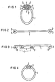
- the cable sleeve shown in Figure 1 according to the invention is shown in the assembled state, that is, the locking system is assembled in the final form.
- the shrinkable sleeve 1, ' which can also be regarded as a sleeve pipe, has, for example, circular beads 2 at the ends.
- longitudinal reinforcing means 3 are embedded according to the invention, which undergo no significant change at the shrinking temperature.
- These reinforcing means 3 can be designed as rods, wires, ropes or fibers made of suitable materials, such as steel, aluminum, glass or also heat-resistant plastic.
- the sleeve 1, or the sleeve pipe is expediently coated on the inward-facing side with an adhesive, preferably hot-melt adhesive which can be activated at the shrinking temperature, so that the final sealing takes place immediately during the shrinking process. From Figure 1 it is also clear that the beads 2 are held in a closure rail 4-5-12. It should be noted that the two beads 2 are held individually and not together, as was mentioned at the beginning in the prior art.
- the locking rail 4-5-12 is now designed to hold the two beads 2 as a symmetrical double C-profile, the C-shapes being placed against one another and being connected to one another via a common central web 12.
- This central web 12 now has a special function with regard to heat conduction; it serves as a good heat conductor to the inner parts of the closure system during the shrinking process. This ensures that the hot melt adhesive is fully and safely activated in the inner areas.
- Figure 2 now shows a sleeve 1 or a sleeve pipe, which can be manufactured in a simple band shape, the longitudinal edges being formed as beads 2 with the embedded reinforcing means 3.
- the beads 2 are circular here.
- FIG. 3 shows one possibility of how a larger diameter range can be covered with a single type of sleeve.
- the beads 8 are only formed on one side, but several of them are arranged in parallel at suitable distances from one another.
- the cuff 1 is initially matched in its width to the largest possible diameter.
- the sleeve 1 is then trimmed by the required width along a bead 8, as the cut edges 7 indicate. This means that the sleeve is no longer as wide as it was originally and is therefore adapted to the smaller diameter of a cable.
- Figure 4 indicates how a sleeve 1 with the beads 2 and the embedded reinforcing means 3 can be produced by extrusion in the form of a tube. Following the manufacturing process of this tube, the two beads 2 are separated by a longitudinal cut.
- Figure 5 now shows a locking rail 4-5-12 according to the invention.
- the two C-profiles placed against each other, which finally form the undercut grooves 6, become clear, wherein they are connected to one another via a common central web 12.
- the ends 4 and 5 are contracted so far that they meet the conditions already described with regard to the beads 2.
- the underside of the closure rail 2 with the ends 5 is coated with an adhesive coating 9, preferably made of hot-melt adhesive. In this way, a fixation is made between the closure rail 4-5-12 and the cable jacket, a sealing body of a cable sleeve or the like during the shrinking process.
- Figure 6 also shows a locking rail 4-5-12 with its two undercut grooves 6, which is provided on the underside to improve the sealing effect with a plastic tape coated with adhesive.
- the same material from which the cuff is made is particularly suitable for this, as a result of this Similar conditions can be achieved in this area as in the rest of the scope.
- the figure shows a closure rail 4-5-12 in a flexible design.
- the upper ends 4 and the central web 12 are provided with ends 5 at suitable intervals, through which the flexibility is determined, with transverse slots 11 up to the underside.
- the closure rail 4-5-12 which now has only one continuous band, can be adapted in accordance with the bends.
- FIG. 8 also shows an embodiment of a closure rail 4-5-12, the underside of which is formed in a circular arc with the ends 5 in order to achieve a better adaptation to the shape of a cable.
- FIG. 9 now shows an example of a closure rail 4-5-12, which can be produced as a stamped and bent part from a sheet metal strip in a simple manner.
- a sheet metal strip is provided with cuts at suitable intervals from both sides, with a distance remaining in the middle which corresponds in width to the later height or groove 6 of the locking rail 4-5-12.
- two opposing sections are bent in pairs as ends 4 and 5 for an undercut groove to one side.
- the next two opposite sections are also bent as ends 4 and 5, but on the other side of the middle web 12 remaining in the middle.
- This change is continued, so that in this way a locking rail 4-5-12 mutually offset Partial grooves 6 'results.
- the length of these partial grooves 6 'must be chosen so that the inserted beads 2 of the sleeve 1 are held securely by the forces acting in the circumferential direction.
Landscapes
- Cable Accessories (AREA)
- Insulated Conductors (AREA)
- Insulating Bodies (AREA)
- Installation Of Indoor Wiring (AREA)
Claims (14)
Priority Applications (1)
| Application Number | Priority Date | Filing Date | Title |
|---|---|---|---|
| AT81101517T ATE5164T1 (de) | 1980-03-10 | 1981-03-03 | Laengsgeteilte kabelmuffe aus schrumpfbarem material. |
Applications Claiming Priority (2)
| Application Number | Priority Date | Filing Date | Title |
|---|---|---|---|
| DE3009078 | 1980-03-10 | ||
| DE3009078A DE3009078C2 (de) | 1980-03-10 | 1980-03-10 | Längsgeteilte Kabelmuffe aus schrumpfbarem Material |
Publications (2)
| Publication Number | Publication Date |
|---|---|
| EP0035737A1 EP0035737A1 (fr) | 1981-09-16 |
| EP0035737B1 true EP0035737B1 (fr) | 1983-10-26 |
Family
ID=6096717
Family Applications (1)
| Application Number | Title | Priority Date | Filing Date |
|---|---|---|---|
| EP81101517A Expired EP0035737B1 (fr) | 1980-03-10 | 1981-03-03 | Manchon de câble divisé longitudinalement en matériau rétractable |
Country Status (6)
| Country | Link |
|---|---|
| US (1) | US4379473A (fr) |
| EP (1) | EP0035737B1 (fr) |
| AT (1) | ATE5164T1 (fr) |
| AU (1) | AU540502B2 (fr) |
| CA (1) | CA1174310A (fr) |
| DE (2) | DE3009078C2 (fr) |
Families Citing this family (31)
| Publication number | Priority date | Publication date | Assignee | Title |
|---|---|---|---|---|
| US4413656A (en) * | 1980-09-13 | 1983-11-08 | Raychem Limited | Wrap-around device |
| DE3234816C2 (de) * | 1982-09-20 | 1984-07-19 | kabelmetal electro GmbH, 3000 Hannover | Verfahren zur Herstellung einer schlauchförmigen, wiederverschließbaren Umhüllung für elektrische Kabel und Rohrleitungen |
| ES8505745A1 (es) * | 1983-01-06 | 1985-06-01 | Raychem Ltd | Un articulo de envoltura encogible |
| DE3479233D1 (en) * | 1983-05-25 | 1989-09-07 | Shaw Ind Ltd | Heat shrinkable covering |
| GB2154808B (en) * | 1984-02-21 | 1987-09-09 | Water Res Centre | Installation of communications cables |
| DE3504380A1 (de) * | 1985-02-08 | 1986-08-14 | Siemens AG, 1000 Berlin und 8000 München | Manschette aus schrumpfbarem material und ein verfahren zur herstellung derselben |
| EP0201922A1 (fr) * | 1985-05-17 | 1986-11-20 | RXS Schrumpftechnik-Garnituren GmbH | Connexion thermorétractable d'une rainure variable et d'un élément fermant |
| DE3518013A1 (de) * | 1985-05-18 | 1986-11-20 | Festo KG, 7300 Esslingen | Flexibler schlauch |
| US4737210A (en) * | 1985-09-09 | 1988-04-12 | Durodyne, Inc. | Method of fabrication of high tensile strength removable hose covering |
| GB8525910D0 (en) * | 1985-10-21 | 1985-11-27 | Raychem Sa Nv | Closure for wraparound sleeve |
| GB8528966D0 (en) * | 1985-11-25 | 1986-01-02 | Raychem Ltd | Wrap-around fabric articles |
| GB8606730D0 (en) * | 1986-03-19 | 1986-04-23 | Raychem Sa Nv | Indicator |
| GB8625125D0 (en) * | 1986-10-20 | 1986-11-26 | Raychem Sa Nv | Wraparound recoverable article |
| DE3643370C3 (de) * | 1986-12-18 | 1996-08-14 | Siemens Ag | Längsgeteiltes Muffenrohr für Kabelmuffen |
| JPH0443674Y2 (fr) * | 1987-02-09 | 1992-10-15 | ||
| US4777072A (en) * | 1987-02-24 | 1988-10-11 | Cason Jr Claude | Pliable sheet and coupling strip |
| US4824707A (en) * | 1988-06-27 | 1989-04-25 | Donald Spector | Decorative air freshener unit |
| DE59302856D1 (de) * | 1992-02-28 | 1996-07-18 | Rxs Schrumpftech Garnituren | Verfahren zur Anformung von Profilen pilzförmigen Querschnittes als Verschlusselemente an wärmeschrumpffähigen Kunststoffbahnen |
| DE9411270U1 (de) * | 1994-07-12 | 1994-09-15 | DSG Schrumpfschlauch GmbH, 53340 Meckenheim | Bausatz zum Befestigen, Führen und Fixieren von Gegenständen |
| US5647358A (en) * | 1996-03-20 | 1997-07-15 | Vilasi; Joseph | Expandable inter vivos tube |
| US6832571B2 (en) * | 2001-10-30 | 2004-12-21 | Albany International Corp. | Segment formed flexible fluid containment vessel |
| US7431126B2 (en) * | 2005-03-15 | 2008-10-07 | Honeywell International Inc. | Support means for an acoustic liner used in an auxiliary power unit exhaust muffler |
| SG11201504481XA (en) * | 2012-12-21 | 2015-07-30 | Gates Corp | Hose burst containment blanket |
| CN104125752A (zh) * | 2013-04-29 | 2014-10-29 | 鸿富锦精密工业(深圳)有限公司 | 导风罩 |
| KR101399421B1 (ko) * | 2013-11-11 | 2014-05-28 | (주)동인엔지니어링 | 압착결합구조의 마감커버를 구비하는 배관용 단열장치 |
| DE102014203223A1 (de) * | 2014-02-24 | 2015-08-27 | Siemens Aktiengesellschaft | Verfahren und Vorrichtung zur Herstellung eines Seekabels sowie damit hergestelltes Seekabel |
| US10128643B2 (en) * | 2016-10-13 | 2018-11-13 | Illinois Tool Works Inc. | Loom assembly providing improved electrical isolation |
| US10059278B1 (en) * | 2017-07-18 | 2018-08-28 | Paul Stotts | System and method for retrofitting vehicles with onboard monitoring equipment |
| JP6881358B2 (ja) * | 2018-03-09 | 2021-06-02 | 住友電装株式会社 | ワイヤハーネス |
| BR112023023477A2 (pt) * | 2021-05-11 | 2024-01-30 | Ratnam Sri Skanda Rajah S | Montagem de tubulação e método para a sua fabricação |
| US20240111102A1 (en) * | 2022-09-30 | 2024-04-04 | Corning Research & Development Corporation | Cable coverings for local convergence points and fiber optic enclosures |
Family Cites Families (11)
| Publication number | Priority date | Publication date | Assignee | Title |
|---|---|---|---|---|
| US1185014A (en) * | 1915-01-27 | 1916-05-30 | Charles T Hughes | Plate-joint, clamping-bar therefor, and process of making said joint. |
| US3455336A (en) * | 1965-11-03 | 1969-07-15 | Raychem Corp | Heat recoverable article and process |
| US3542077A (en) * | 1968-05-22 | 1970-11-24 | Raychem Corp | Differentially cross-linked article and process for making the same |
| DE2441668B2 (de) * | 1974-08-30 | 1976-07-01 | Siemens AG, 1000 Berlin und 8000 München | Kabelgarnitur aus schrumpfbarem material |
| US3991243A (en) * | 1974-12-09 | 1976-11-09 | Raychem Corporation | Method of making a reinforced insert weld and resulting article |
| CA1048118A (fr) * | 1975-05-23 | 1979-02-06 | George W. Gillemot | Protege-epissures a fente longitudinale a bande de serrage souple |
| GB1561125A (en) * | 1975-08-04 | 1980-02-13 | Raychem Sa Nv | Heat recoverable article |
| GB1604440A (en) * | 1977-12-23 | 1981-12-09 | Raychem Sa Nv | Heatrecoverable wrap-around devices |
| DE2816623C3 (de) | 1978-04-17 | 1980-10-16 | Siegfried 5800 Hagen Mueller | Vorrichtung zum Abdichten von Verbindungsstellen an einem durchlaufenden Gegenstand, insbesondere von Kabelmuffen |
| DE2832485B2 (de) * | 1978-07-24 | 1980-08-28 | Siemens Ag, 1000 Berlin Und 8000 Muenchen | Kabelgarnitur aus schrumpfbarem Material mit dauerplastischer Dichtungseinlage |
| US4268559A (en) * | 1978-09-22 | 1981-05-19 | Electronized Chemicals Corporation | Heat-shrinkable article |
-
1980
- 1980-03-10 DE DE3009078A patent/DE3009078C2/de not_active Expired
-
1981
- 1981-02-20 US US06/236,526 patent/US4379473A/en not_active Expired - Fee Related
- 1981-03-03 AT AT81101517T patent/ATE5164T1/de not_active IP Right Cessation
- 1981-03-03 DE DE8181101517T patent/DE3161259D1/de not_active Expired
- 1981-03-03 EP EP81101517A patent/EP0035737B1/fr not_active Expired
- 1981-03-06 CA CA000372468A patent/CA1174310A/fr not_active Expired
- 1981-03-09 AU AU68179/81A patent/AU540502B2/en not_active Ceased
Also Published As
| Publication number | Publication date |
|---|---|
| AU540502B2 (en) | 1984-11-22 |
| DE3161259D1 (en) | 1983-12-01 |
| DE3009078C2 (de) | 1983-01-20 |
| DE3009078A1 (de) | 1981-09-17 |
| EP0035737A1 (fr) | 1981-09-16 |
| US4379473A (en) | 1983-04-12 |
| ATE5164T1 (de) | 1983-11-15 |
| CA1174310A (fr) | 1984-09-11 |
| AU6817981A (en) | 1981-09-17 |
Similar Documents
| Publication | Publication Date | Title |
|---|---|---|
| EP0035737B1 (fr) | Manchon de câble divisé longitudinalement en matériau rétractable | |
| EP0056080A1 (fr) | Manchon fendu longitudinalement en matière synthétique thermoplastique à mémoire de forme | |
| DE2820181C3 (de) | Verschluß für ein längsgeschlitztes Kabelmuffenrohr | |
| DE2600647A1 (de) | Waerme-verformbare teile | |
| EP0085410A2 (fr) | Procédé pour réunir les parties métalliques intérieures et extérieures d'un profile composite | |
| EP0471892B1 (fr) | Couverture composite comprenant au moins une feuille renforcée, thermo-rétractable, et son procédé de fabrication | |
| EP0226940B1 (fr) | Manchon de câble rétractable | |
| EP0118701A2 (fr) | Procédé de fabrication d'une fixation pour tubes métalliques d'échangeur de chaleur avec une plaque tubulaire d'une boîte à eau | |
| DE69412089T2 (de) | Vorrichtung mit seitlicher Öffnung zum Abdichten von Drahtbündeln | |
| EP0421316A2 (fr) | Joint d'étanchéité et de remplissage verrouillable, en particulier pour fenêtre de véhicule automobile | |
| DE3504380A1 (de) | Manschette aus schrumpfbarem material und ein verfahren zur herstellung derselben | |
| DE3101256A1 (de) | Laengsgeteilte kabelmuffe mit einem muffenrohr aus thermoplastischem, schrumpfbarem kunststoff | |
| EP0203497B1 (fr) | Enveloppe tubulaire divisée longitudinalement, en particulier manchon de câble, en matériau rétractable | |
| DE69611998T2 (de) | Stange eines gepäckträgers und verfahren zur herstellung | |
| DE2729757A1 (de) | Klemmprofil, wie kantenschutzprofil, mit einer elastischen verstaerkungseinlage | |
| DE3616535C2 (de) | Kabelmuffe aus einem Muffenrohr und aus zwei seitlich sich anschließenden, schrumpfbaren Muffenköpfen | |
| EP0503463B1 (fr) | Procédé de fabrication d'éléments thermorétractables et éléments obtenus par ce procédé | |
| DE2742760A1 (de) | Elastische abdichtung von trennfugen zwischen dichtungskoerpern und muffenrohr sowie von trennebenen des muffenrohres bei thermoplastklemmuffen | |
| DE3234816C2 (de) | Verfahren zur Herstellung einer schlauchförmigen, wiederverschließbaren Umhüllung für elektrische Kabel und Rohrleitungen | |
| EP0472056A1 (fr) | Element de raccord pour tuyaux | |
| DE3341618A1 (de) | Stirnseitige abdichtung einer schrumpfbaren kabelgarnitur | |
| DE3038922A1 (de) | Schlauchfoermige garnitur fuer elektrische kabel und rohrleitungen und verfahren zu ihrer herstellung | |
| DE3527633A1 (de) | Unter beibehaltung seiner raeumlichen ausdehnung rueckformendes formteil | |
| DE3524598A1 (de) | Schlauchfoermige garnitur fuer elektrische kabel und rohrleitungen | |
| DE2909979C2 (de) | Vorrichtung zum Abdichten von Verbindungsstellen an einem durchlaufenden Gegenstand, insbesondere von Kabelmuffen |
Legal Events
| Date | Code | Title | Description |
|---|---|---|---|
| PUAI | Public reference made under article 153(3) epc to a published international application that has entered the european phase |
Free format text: ORIGINAL CODE: 0009012 |
|
| AK | Designated contracting states |
Designated state(s): AT BE CH DE FR GB IT LU NL SE |
|
| 17P | Request for examination filed |
Effective date: 19811006 |
|
| ITF | It: translation for a ep patent filed | ||
| GRAA | (expected) grant |
Free format text: ORIGINAL CODE: 0009210 |
|
| AK | Designated contracting states |
Designated state(s): AT BE CH DE FR GB IT LI LU NL SE |
|
| REF | Corresponds to: |
Ref document number: 5164 Country of ref document: AT Date of ref document: 19831115 Kind code of ref document: T |
|
| REF | Corresponds to: |
Ref document number: 3161259 Country of ref document: DE Date of ref document: 19831201 |
|
| ET | Fr: translation filed | ||
| PLBE | No opposition filed within time limit |
Free format text: ORIGINAL CODE: 0009261 |
|
| STAA | Information on the status of an ep patent application or granted ep patent |
Free format text: STATUS: NO OPPOSITION FILED WITHIN TIME LIMIT |
|
| 26N | No opposition filed | ||
| ITTA | It: last paid annual fee | ||
| PGFP | Annual fee paid to national office [announced via postgrant information from national office to epo] |
Ref country code: GB Payment date: 19930216 Year of fee payment: 13 |
|
| PGFP | Annual fee paid to national office [announced via postgrant information from national office to epo] |
Ref country code: AT Payment date: 19930224 Year of fee payment: 13 |
|
| PGFP | Annual fee paid to national office [announced via postgrant information from national office to epo] |
Ref country code: BE Payment date: 19930312 Year of fee payment: 13 |
|
| PGFP | Annual fee paid to national office [announced via postgrant information from national office to epo] |
Ref country code: SE Payment date: 19930316 Year of fee payment: 13 |
|
| PGFP | Annual fee paid to national office [announced via postgrant information from national office to epo] |
Ref country code: FR Payment date: 19930319 Year of fee payment: 13 |
|
| PGFP | Annual fee paid to national office [announced via postgrant information from national office to epo] |
Ref country code: NL Payment date: 19930331 Year of fee payment: 13 |
|
| PGFP | Annual fee paid to national office [announced via postgrant information from national office to epo] |
Ref country code: LU Payment date: 19930406 Year of fee payment: 13 |
|
| PGFP | Annual fee paid to national office [announced via postgrant information from national office to epo] |
Ref country code: DE Payment date: 19930518 Year of fee payment: 13 |
|
| PGFP | Annual fee paid to national office [announced via postgrant information from national office to epo] |
Ref country code: CH Payment date: 19930621 Year of fee payment: 13 |
|
| EPTA | Lu: last paid annual fee | ||
| PG25 | Lapsed in a contracting state [announced via postgrant information from national office to epo] |
Ref country code: LU Free format text: LAPSE BECAUSE OF NON-PAYMENT OF DUE FEES Effective date: 19940303 Ref country code: GB Effective date: 19940303 Ref country code: AT Effective date: 19940303 |
|
| PG25 | Lapsed in a contracting state [announced via postgrant information from national office to epo] |
Ref country code: SE Free format text: LAPSE BECAUSE OF NON-PAYMENT OF DUE FEES Effective date: 19940304 |
|
| PG25 | Lapsed in a contracting state [announced via postgrant information from national office to epo] |
Ref country code: LI Effective date: 19940331 Ref country code: CH Effective date: 19940331 Ref country code: BE Effective date: 19940331 |
|
| BERE | Be: lapsed |
Owner name: SIEMENS A.G. BERLIN UND MUNCHEN Effective date: 19940331 |
|
| PG25 | Lapsed in a contracting state [announced via postgrant information from national office to epo] |
Ref country code: NL Effective date: 19941001 |
|
| GBPC | Gb: european patent ceased through non-payment of renewal fee |
Effective date: 19940303 |
|
| NLV4 | Nl: lapsed or anulled due to non-payment of the annual fee | ||
| PG25 | Lapsed in a contracting state [announced via postgrant information from national office to epo] |
Ref country code: FR Effective date: 19941130 |
|
| REG | Reference to a national code |
Ref country code: CH Ref legal event code: PL |
|
| PG25 | Lapsed in a contracting state [announced via postgrant information from national office to epo] |
Ref country code: DE Effective date: 19941201 |
|
| REG | Reference to a national code |
Ref country code: FR Ref legal event code: ST |
|
| EUG | Se: european patent has lapsed |
Ref document number: 81101517.1 Effective date: 19941010 |