EP0036393A1 - Vorrichtung zum Zuführen steriler Gegenstände, die in inwendig sterilen Behältern enthalten sind, zu einer sterilen Verpackungsanlage - Google Patents
Vorrichtung zum Zuführen steriler Gegenstände, die in inwendig sterilen Behältern enthalten sind, zu einer sterilen Verpackungsanlage Download PDFInfo
- Publication number
- EP0036393A1 EP0036393A1 EP81830027A EP81830027A EP0036393A1 EP 0036393 A1 EP0036393 A1 EP 0036393A1 EP 81830027 A EP81830027 A EP 81830027A EP 81830027 A EP81830027 A EP 81830027A EP 0036393 A1 EP0036393 A1 EP 0036393A1
- Authority
- EP
- European Patent Office
- Prior art keywords
- chamber
- receptacle
- aperture
- sterile
- tubular element
- Prior art date
- Legal status (The legal status is an assumption and is not a legal conclusion. Google has not performed a legal analysis and makes no representation as to the accuracy of the status listed.)
- Granted
Links
- 238000012856 packing Methods 0.000 title claims description 6
- 230000007246 mechanism Effects 0.000 claims description 11
- 230000000903 blocking effect Effects 0.000 claims description 2
- ATJFFYVFTNAWJD-UHFFFAOYSA-N Tin Chemical compound [Sn] ATJFFYVFTNAWJD-UHFFFAOYSA-N 0.000 description 6
- 239000002184 metal Substances 0.000 description 5
- 230000001954 sterilising effect Effects 0.000 description 3
- 238000013459 approach Methods 0.000 description 2
- 239000012530 fluid Substances 0.000 description 2
- 239000003380 propellant Substances 0.000 description 2
- 230000004888 barrier function Effects 0.000 description 1
- 239000002775 capsule Substances 0.000 description 1
- 230000006735 deficit Effects 0.000 description 1
- 230000036512 infertility Effects 0.000 description 1
- 238000012986 modification Methods 0.000 description 1
- 230000004048 modification Effects 0.000 description 1
- 238000007789 sealing Methods 0.000 description 1
- 238000004659 sterilization and disinfection Methods 0.000 description 1
- 239000008256 whipped cream Substances 0.000 description 1
Images

Classifications
-
- B—PERFORMING OPERATIONS; TRANSPORTING
- B65—CONVEYING; PACKING; STORING; HANDLING THIN OR FILAMENTARY MATERIAL
- B65B—MACHINES, APPARATUS OR DEVICES FOR, OR METHODS OF, PACKAGING ARTICLES OR MATERIALS; UNPACKING
- B65B37/00—Supplying or feeding fluent-solid, plastic, or liquid material, or loose masses of small articles, to be packaged
-
- B—PERFORMING OPERATIONS; TRANSPORTING
- B65—CONVEYING; PACKING; STORING; HANDLING THIN OR FILAMENTARY MATERIAL
- B65B—MACHINES, APPARATUS OR DEVICES FOR, OR METHODS OF, PACKAGING ARTICLES OR MATERIALS; UNPACKING
- B65B55/00—Preserving, protecting or purifying packages or package contents in association with packaging
- B65B55/02—Sterilising, e.g. of complete packages
Definitions
- This invention concerns a feeding device for pre-sterilized objects contained in internally sterile receptacles, for sterile packing plants.
- the pre-sterilized objects will be identified as nozzles for closing pressurized tins containing food stuffs and propellant gas under pressure in order to force the products out of the pressurized tin; it is obvious however, that the different nature of these objects which could consist of various types of lids and caps, twist-off type capsules, etc. does not alter the essence of that which will be described hereunder.
- the empty tin After passing through a sterilizing tunnel, arrives in a sterile area, where the product is introduced into the tin, the tin itself is closed by means of a nozzle and the tin is then charged with propellant gas for the purpose of forcing the product out of the pressurized tin.
- These nozzles reach the tin-closing device in the sterile area after passing through a vibrating device which is also maintained in a sterile atmosphere, and which lines them up neatly on a conveyor and sends them on to the closing device.
- the nozzles reach the plant which packs the product, already pre-sterilized and sealed in receptacles which contain large quantities of them.
- the inside of the receptacle is sterile as these receptacles are provided with airtight lids.
- the aim of this invention is to resolve the above-mentioned problem by providing a feeding device by means of which it is possible to remove the nozzles from the receptacle and to dispatch them to the closing device without impairment to their state of sterility.
- a further aim of this invention is that of providing a feeding device which is simple, compact and easily adaptable to a sterile packing line.
- a further aim of this invention is that of providing a device which does not call for the use of special clothing for the operators in charge of it.
- a still further aim of this invention is that of providing a feeding device which guarantees without a doubt that the operations are carried out in a sterile atmosphere.
- the device in question characterized by the fact of comprising: a chamber provided with two apertures, the first of which connects the chamber, by means of an opening and closing mechanism operated from the outside of said chamber, with a sterile environment, and the second of which is shaped in such a way that the mouth of the receptacle containing the pre-sterilized objects passes through it, blocking it completely; a first means for creating, within said chamber, an atmosphere of sterile gas at a pressure which is slightly higher than the atmospheric pressure; a locking means for securing said receptacle in the position in which the mouth of the latter occupies the second aperture; a second means, operated from outside said chamber for removing the lid of said receptacle when the latter is secured by said locking means; a diaphragm, situated between said first and second aperture for greatly reducing the sectional area of flow towards the outside of the gas contained in the chamber when said second aperture is free.
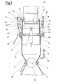
- the device illustrated comprises a chamber (1) which in turn comprises a first tubular element (1a) and a second tubular element (1b), arranged coaxially one inside the other and being able to slide axially one with respect to the other.
- the chamber (1) is provided with a first aperture (2) and a second aperture (3) which are situated, the first aperture (2) on the outer base of the first tubular element and the second aperture (3) on the outer base of the second tubular element.
- the first aperture (2) has a smaller cross-section with respect to the cross-section of the first tubular element and is provided with an opening and closing mechanism consisting of a butterfly valve (4), the butterfly of which, when in closed position, occupies the entire span of said first aperture.
- the valve (4) is operated from outside the chamber (1) by manual rotation of a first operating lever (4b).
- the aperture (2) connects the chamber (1) with a sterile environment (5).
- a conveyor (6) leads off from the environment (5) which, passing through an internally sterile tunnel, arrives at the filling and seal ing area (7) of the pressurized tins (8).
- k sterile atmosphere is obviously also maintained in the area (7).
- a plate (9) Integrally fixed to the outer base of the second tubular element is a plate (9) out of which the said second aperture (3) is cut.
- This aperture (3) is shaped in such a way as to allow the mouth (10a) of a receptacle (10) containing the pre-sterilized nozzles (11) to enter it.
- the receptacle (10) is secured to the plate (9) by means of a locking means consisting of a clamp (12) which engages with a recess (13) situated on the side of the receptacle (10) in the position in which the mouth of the latter occupies the second aperture (3).
- the cross-section of the tubular elements will obviously be such as to easily contain the lid itself.
- the tubular elements (1a) and (1b) are arranged perpendicular to the base and the receptacle (10) is secured coaxially to said tubular elements so that the lid (10b) of the receptacle (10), which is of the pressure type, is substantially perpendicular to the common axis of the receptacle and the tubular elements.
- the device comprises a second means, operated from outside the chamber (1), for removing the lid of the receptacle (10) when the latter is secured to the plate (9) by the clamp (12).
- This second means comprises a gripping means, situated within the chamber (1), connected to the first tubular element and operated from outside the chamber itself, for firmly gripping the lid (10b) of the receptacle (10) when it is secured to the plate (9), and mechanisms acting upon the second tubular element which push the gripping means and the receptacle together and apart.
- the gripping means comprises a frame (15) closed from below, arranged parallel to the surface containing the lid of the receptacle (10) when the latter is secured to the plate (9), and provided with a pair of jaws (16) and (17) situated facing each other.
- the jaw (16) is integral with the frame whereas the jaw (17) slides in the radial direction of the frame so as to approach and move away from the jaw (16). When the jaws are fully apart, the lid of the receptacle can be inserted between them.
- the lid (10b) of the receptacle is provided with an undercut circumferential groove (18) and the jaws (16) and (17) are each provided with a rim (16a) and (17a) respective ly, which extends over an arc of a circle and which is slightly thinner than the depth of the groove (18).
- a third means operated from outside the chamber (1) is provided, for causing the rotation of the frame (15) in order to make it assume an inclined position with respect to the axis of the tubular elements or complanate with said axis.
- the frame (15) is fitted to journals (20) and (21) rotating idle within the housings on the first tubular element (1a).
- a second operating lever (23) is fitted to the end of the journal (21) which protrudes from the tubular element (1a), which is operated manually in order to permit the rotation of the frame (15).
- journal (20) The internal end of the journal (20) is integrally secured to the jaw (17) whilst a threaded nut (24) which engages with a threaded surface fixed with respect to the tubular element (1a), is connected in coincidence with the axial traverse of the journal (20), to its external end.
- the area occupied by the frame (15) when the latter is arranged perpendicularly to the axis of the tubular elements, is slightly smaller than the area of the cross-section of the chamber (1), therefore there is a small gap between,the external perimeter of the frame and the inner wall of the chamber.
- the frame (15) which is situated between the apertures (2) and (3) therefore constitutes a barrier for greatly reducing the sectional area of flow of the gas contained in the chamber, towards the outside; as it will be more clearly described whilst operating the device, the frame carries out its function of reducing the sectional area of flow of air especially when the aperture (3) is free, that is to say, when the receptacle (10) is not inserted in the latter, insofar as during this phase the frame (15) is perpendicular to the axis of the tubular elements which form the chamber (1).
- Said mechanisms comprise a pair of levers (26) and (27) hinged onto rods (28) and (29) respectively, which are integrally fitted to the first tubular element; the levers (26) and (27) are arranged on opposite sides with respect to the chamber (1) and are substantially parallel to each other.
- each lever is connected, by means of a connecting rod (30) and (31) respectively, to the plate (9) of the second tubular element; the other ends of the levers are connected together by means of a crosspiece (33).
- a jack (34), the cylinder of which is connected to the first tubular element and the piston of which is connected to the crosspiece (33) causes, on command, the simultaneous rotation of the levers (26) and (27) and thereby, the lowering and raising of the second tubular element.
- the second tubular element is provided with two lengthwise slits (35) and (36) respectively, which can slide on the supports of the journals (20) and (21) supporting the frame (15).
- Two metal strips (37) and (38) connected, on one end, to the supports of the journals (20) and (21), are provided inside the chamber (1) to protect the slits (35) and (36); the other end of each metal strip protrudes from appropriate holes in the plate (9).
- the device in question comprises moreover, a first means for creating an atmosphere of sterile gas within the chamber, at a pressure which is slightly higher than the atmospheric pressure, for purposes which will be explained more clearly during the description of the functioning of the device.
- This first means comprises a sterile-air generator, not shown in the figures, which sends sterile air into the area beneath the frame (15) of the chamber (1) through a duct (40).
- first position the position in which the second tubular element is partially withdrawn from the first tubular element and the plate (9) is at a distance from the frame (15)
- second position the position in which the second tubular element is inserted into the first tubular element and the plate (9) is close to the frame (15)
- a sterile atmosphere is continuously maintained in the environment (5).
- the butterfly valve (4) is closed, the second tubular element is in the second position, the second aperture (3) is free and the frame (15) is situated parallel to the plate (9). There may be external and, therefore, non-sterile air above the frame which enters the aperture (3).
- the air does not enter the lower part of the chamber (1) as it is prevented by the frame itself; in fact, the sectional area of flow bet ween the frame and the inner wall of the chamber is such that, due to the overpressure existing within the chamber itself, the flow of air occurs from the lower part of the chamber towards the outside and not vice-versa.
- both the lid (10b) and the neck of the receptacle, and also the upper part of the frame (15) are thoroughly soaked with sterilizing fluid.
- This fluid is dried by the sterile air flowing from the inside to the outside of the chamber (1) and is, in any event, in such a position as never to come into contact with the nozzles contained in the receptacle.
- the aperture (3) is then blocked by the receptacle (10).
- the first function of the metal strips (37) and (38) is that of preventing an excessive quantity of air from escaping through the slits (35) and (36), which would otherwise call for a considerable flow of sterile air through the duct (40).
- the lid (10b) of the receptable is situated between the jaws of the frame (15).
- the jaw (17) By acting upon the nut (24) the jaw (17) approaches the jaw (16) and the rims (16a) and (17a) of the jaws fit into the groove (18), thus making the lid (10b) integral with the frame (15).
- the rim (16a) of the fixed jaw (16) is able to enter the groove (18) due to the fact that, in closing, the mobile jaw (17) causes slight movement of the receptacle (10).
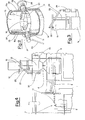
- Operating the jack (34) brings the second tubular element into the first position (fig. 6).
- the lid (10b) which is integral with the frame (15) is removed from the receptacle (10), thus causing the nozzles (11) to fall from the receptacle.
- a further function of the metal strips (37) and (38) is that of preventing any nozzles (11) from becoming stuck in the slits (35) and (36).
- the raising of the second tubular element must be carried out slowly so as not to cause a rapid increase in the volume in the chamber (1) which would consequently bring about a sharp drop in the pressure within the chamber itself, together with a possible intake of non-sterile external air.
- the frame (15) is then returned to its original position.
- the butterfly (4a) of the valve (4) is turned (fig. 8) by operating the lever (4b), thus permitting the nozzles to enter the sterile environment (5) from whence, through a device not shown in the figures, they will be conveyed, by the means previously described or by other equivalent means, to the sterile area (7) where the pressurized tins (8) will be sealed.
- the butterfly valve is then reclosed.
- the device is returned to the second position (fig. 9).
- the clamp (12) is released thus releasing the receptacle (10) which is removed from the plate (9); acting upon the nut (24) the lid, which was held integral with the frame (15), is then released and is removed by hand from the device which is now ready to receive another full receptacle, which is inserted immediately, and to recommence the above-described cycle of operations.
- the nozzles are kept continuous ly in a sterile atmosphere and therefore free from the danger of pollution.
Landscapes
- Engineering & Computer Science (AREA)
- Mechanical Engineering (AREA)
- Vacuum Packaging (AREA)
- Agricultural Chemicals And Associated Chemicals (AREA)
- Auxiliary Devices For And Details Of Packaging Control (AREA)
- Control And Other Processes For Unpacking Of Materials (AREA)
- Packaging Of Special Articles (AREA)
- Apparatus For Disinfection Or Sterilisation (AREA)
Priority Applications (1)
| Application Number | Priority Date | Filing Date | Title |
|---|---|---|---|
| AT81830027T ATE8861T1 (de) | 1980-02-29 | 1981-02-25 | Vorrichtung zum zufuehren steriler gegenstaende, die in inwendig sterilen behaeltern enthalten sind, zu einer sterilen verpackungsanlage. |
Applications Claiming Priority (2)
| Application Number | Priority Date | Filing Date | Title |
|---|---|---|---|
| IT40014/80A IT1136295B (it) | 1980-02-29 | 1980-02-29 | Dispositivo di alimentazione di oggetti presterilizzati,racchiusi in contenitori internamente sterili per impianto di confezionamento sterile |
| IT4001480 | 1980-02-29 |
Publications (2)
| Publication Number | Publication Date |
|---|---|
| EP0036393A1 true EP0036393A1 (de) | 1981-09-23 |
| EP0036393B1 EP0036393B1 (de) | 1984-08-08 |
Family
ID=11246538
Family Applications (1)
| Application Number | Title | Priority Date | Filing Date |
|---|---|---|---|
| EP81830027A Expired EP0036393B1 (de) | 1980-02-29 | 1981-02-25 | Vorrichtung zum Zuführen steriler Gegenstände, die in inwendig sterilen Behältern enthalten sind, zu einer sterilen Verpackungsanlage |
Country Status (7)
| Country | Link |
|---|---|
| US (1) | US4381067A (de) |
| EP (1) | EP0036393B1 (de) |
| JP (1) | JPS5944251B2 (de) |
| AT (1) | ATE8861T1 (de) |
| CA (1) | CA1160812A (de) |
| DE (1) | DE3165319D1 (de) |
| IT (1) | IT1136295B (de) |
Cited By (2)
| Publication number | Priority date | Publication date | Assignee | Title |
|---|---|---|---|---|
| FR2773714A1 (fr) * | 1998-01-20 | 1999-07-23 | Becton Dickinson France | Procede d'introduction d'objets conditionnes dans une zone sterile |
| FR2773715A1 (fr) * | 1998-01-20 | 1999-07-23 | Becton Dickinson France | Procede d'introduction d'objets conditionnes dans une zone sterile |
Families Citing this family (9)
| Publication number | Priority date | Publication date | Assignee | Title |
|---|---|---|---|---|
| FR2511149A1 (fr) * | 1981-08-04 | 1983-02-11 | Roussel Uclaf | Dispositif et procede de dosage de quantites predeterminees d'au moins un produit |
| JPH0411990Y2 (de) * | 1987-06-27 | 1992-03-24 | ||
| US5050778A (en) * | 1989-12-19 | 1991-09-24 | Pat Corrado | Dry flowable material dispensing and contents preservation and sterilization apparatus |
| US5832973A (en) * | 1997-10-14 | 1998-11-10 | Bristol-Myers Squibb Company | Sanitary carbon charging system |
| SE9802405L (sv) * | 1998-07-03 | 1999-09-06 | Getinge Ab | Doseringsanordning i steril miljö |
| ITPT990016A1 (it) * | 1999-08-27 | 2001-02-27 | Salvatore Lardieri | Sistema atto a consentire il permanere delle condizioni di sterilita'del prodotto contenuto all'interno di una struttura durante l'accoppia |
| US6988865B2 (en) * | 2003-04-11 | 2006-01-24 | Cardwell Steven A | Barrel handling system |
| US10699181B2 (en) | 2016-12-30 | 2020-06-30 | Google Llc | Virtual assistant generation of group recommendations |
| WO2025219930A1 (en) * | 2024-04-18 | 2025-10-23 | Phizero Srl | System for dispensing sterile elements from a sterile storage to an environment for aseptic processes |
Citations (1)
| Publication number | Priority date | Publication date | Assignee | Title |
|---|---|---|---|---|
| DE2811652A1 (de) * | 1978-03-17 | 1979-09-20 | Hermann Jun Schmitz | Fuell- und entleervorrichtung fuer behaelter zur aufnahme pulver- und staubfoermiger materialien, insbesondere zur wartung von feuerloeschgeraeten |
Family Cites Families (4)
| Publication number | Priority date | Publication date | Assignee | Title |
|---|---|---|---|---|
| US1442138A (en) * | 1921-05-12 | 1923-01-16 | Multiplex Packeting And Fillin | Receptacle filling and measuring machine for liquids |
| DE1017454B (de) | 1954-05-18 | 1957-10-10 | Allgaeuer Alpenmilch | Verfahren und Vorrichtung zum sterilen Abpacken von Fluessigkeiten, insbesondere Milch |
| US2817463A (en) * | 1955-05-13 | 1957-12-24 | Stokes Rupert Octavius | Valve arrangement for the discharge of material from a space below atmospheric pressure and like purposes |
| US4212331A (en) * | 1978-12-01 | 1980-07-15 | Victor Benatar | Pressurized apparatus for discharging powdered reagent from a shipping container |
-
1980
- 1980-02-29 IT IT40014/80A patent/IT1136295B/it active
-
1981
- 1981-02-18 US US06/235,740 patent/US4381067A/en not_active Expired - Lifetime
- 1981-02-25 DE DE8181830027T patent/DE3165319D1/de not_active Expired
- 1981-02-25 EP EP81830027A patent/EP0036393B1/de not_active Expired
- 1981-02-25 AT AT81830027T patent/ATE8861T1/de not_active IP Right Cessation
- 1981-02-27 CA CA000371958A patent/CA1160812A/en not_active Expired
- 1981-02-27 JP JP56027073A patent/JPS5944251B2/ja not_active Expired
Patent Citations (1)
| Publication number | Priority date | Publication date | Assignee | Title |
|---|---|---|---|---|
| DE2811652A1 (de) * | 1978-03-17 | 1979-09-20 | Hermann Jun Schmitz | Fuell- und entleervorrichtung fuer behaelter zur aufnahme pulver- und staubfoermiger materialien, insbesondere zur wartung von feuerloeschgeraeten |
Cited By (2)
| Publication number | Priority date | Publication date | Assignee | Title |
|---|---|---|---|---|
| FR2773714A1 (fr) * | 1998-01-20 | 1999-07-23 | Becton Dickinson France | Procede d'introduction d'objets conditionnes dans une zone sterile |
| FR2773715A1 (fr) * | 1998-01-20 | 1999-07-23 | Becton Dickinson France | Procede d'introduction d'objets conditionnes dans une zone sterile |
Also Published As
| Publication number | Publication date |
|---|---|
| US4381067A (en) | 1983-04-26 |
| DE3165319D1 (en) | 1984-09-13 |
| CA1160812A (en) | 1984-01-24 |
| IT8040014A0 (it) | 1980-02-29 |
| EP0036393B1 (de) | 1984-08-08 |
| IT1136295B (it) | 1986-08-27 |
| ATE8861T1 (de) | 1984-08-15 |
| JPS5944251B2 (ja) | 1984-10-27 |
| JPS56161924A (en) | 1981-12-12 |
Similar Documents
| Publication | Publication Date | Title |
|---|---|---|
| US4381067A (en) | Feeding device for pre-sterilized objects contained in internally sterile receptacles, for sterile packing plants | |
| EP0616945B1 (de) | Verfahren und Vorrichtung zum Abfüllen von gefährlichen Stoffen in Behälter | |
| US6070622A (en) | High speed aseptic filling machine | |
| DE2539818C3 (de) | Gefriertrocknungsanlage | |
| EP3125953B1 (de) | Sterilisiermaschine für lose produkte | |
| NL1004742C2 (nl) | Inrichting voor het uit een verpakking nemen van een baal, in het bijzonder een baal tabak. | |
| US3851437A (en) | Receptacle evacuation apparatus and method | |
| US3220153A (en) | Container vacuum capping method | |
| US4363203A (en) | Liquid fill apparatus | |
| US2559368A (en) | Bag forming and sealing machine | |
| US2335738A (en) | Packaging machine | |
| US2874523A (en) | Method and apparatus for aseptically canning under pressure | |
| GB2040862A (en) | Packaging apparatus | |
| US4094121A (en) | Method and apparatus for packing products in substantially oxygen free atmosphere | |
| US3046713A (en) | Combination vacuum lifter and bag clipping assembly | |
| US3686824A (en) | Bottle handling apparatus | |
| US2950829A (en) | Carrier removal apparatus | |
| US2781622A (en) | Packaging device | |
| EP1680324A1 (de) | Verfahren und anordnung zum leeren von grossen beuteln | |
| US2998686A (en) | Apparatus for the closure under high vacuum of glass bottles and small bottles | |
| DE1057953B (de) | Einrichtung zum Evakuieren und Begasen von Beutelpackungen an Fuell- und Schliessmaschinen | |
| US3473290A (en) | Apparatus for stacking and packing articles | |
| GB2069060A (en) | Dispensing viscous substances | |
| EP0911260B1 (de) | Füllorgan für eine aseptische Füllmaschine, insbesondere für flexible Behälter mit Druckkappe | |
| CN207467073U (zh) | 一种胶塞清洗机胶塞袋自动排列装置 |
Legal Events
| Date | Code | Title | Description |
|---|---|---|---|
| PUAI | Public reference made under article 153(3) epc to a published international application that has entered the european phase |
Free format text: ORIGINAL CODE: 0009012 |
|
| AK | Designated contracting states |
Designated state(s): AT BE CH DE FR GB LI LU NL SE |
|
| 17P | Request for examination filed |
Effective date: 19811112 |
|
| GRAA | (expected) grant |
Free format text: ORIGINAL CODE: 0009210 |
|
| RAP1 | Party data changed (applicant data changed or rights of an application transferred) |
Owner name: ROSSI & CATELLI S.P.A. |
|
| AK | Designated contracting states |
Designated state(s): AT BE CH DE FR GB LI LU NL SE |
|
| PG25 | Lapsed in a contracting state [announced via postgrant information from national office to epo] |
Ref country code: SE Effective date: 19840808 Ref country code: NL Effective date: 19840808 Ref country code: LI Effective date: 19840808 Ref country code: CH Effective date: 19840808 Ref country code: BE Effective date: 19840808 Ref country code: AT Effective date: 19840808 |
|
| REF | Corresponds to: |
Ref document number: 8861 Country of ref document: AT Date of ref document: 19840815 Kind code of ref document: T |
|
| REF | Corresponds to: |
Ref document number: 3165319 Country of ref document: DE Date of ref document: 19840913 |
|
| REG | Reference to a national code |
Ref country code: CH Ref legal event code: PL |
|
| ET | Fr: translation filed | ||
| NLV1 | Nl: lapsed or annulled due to failure to fulfill the requirements of art. 29p and 29m of the patents act | ||
| PG25 | Lapsed in a contracting state [announced via postgrant information from national office to epo] |
Ref country code: LU Free format text: LAPSE BECAUSE OF NON-PAYMENT OF DUE FEES Effective date: 19850228 |
|
| PLBE | No opposition filed within time limit |
Free format text: ORIGINAL CODE: 0009261 |
|
| STAA | Information on the status of an ep patent application or granted ep patent |
Free format text: STATUS: NO OPPOSITION FILED WITHIN TIME LIMIT |
|
| 26N | No opposition filed | ||
| PGFP | Annual fee paid to national office [announced via postgrant information from national office to epo] |
Ref country code: FR Payment date: 19980210 Year of fee payment: 18 |
|
| PGFP | Annual fee paid to national office [announced via postgrant information from national office to epo] |
Ref country code: GB Payment date: 19980216 Year of fee payment: 18 |
|
| PGFP | Annual fee paid to national office [announced via postgrant information from national office to epo] |
Ref country code: DE Payment date: 19980306 Year of fee payment: 18 |
|
| PG25 | Lapsed in a contracting state [announced via postgrant information from national office to epo] |
Ref country code: GB Free format text: LAPSE BECAUSE OF NON-PAYMENT OF DUE FEES Effective date: 19990225 |
|
| GBPC | Gb: european patent ceased through non-payment of renewal fee |
Effective date: 19990225 |
|
| PG25 | Lapsed in a contracting state [announced via postgrant information from national office to epo] |
Ref country code: FR Free format text: LAPSE BECAUSE OF NON-PAYMENT OF DUE FEES Effective date: 19991029 |
|
| PG25 | Lapsed in a contracting state [announced via postgrant information from national office to epo] |
Ref country code: DE Free format text: LAPSE BECAUSE OF NON-PAYMENT OF DUE FEES Effective date: 19991201 |
|
| REG | Reference to a national code |
Ref country code: FR Ref legal event code: ST |