EP0037164A2 - Selbstorganisierender Trenner und Identifizierer von allgemeinen Formklassen - Google Patents
Selbstorganisierender Trenner und Identifizierer von allgemeinen Formklassen Download PDFInfo
- Publication number
- EP0037164A2 EP0037164A2 EP81300559A EP81300559A EP0037164A2 EP 0037164 A2 EP0037164 A2 EP 0037164A2 EP 81300559 A EP81300559 A EP 81300559A EP 81300559 A EP81300559 A EP 81300559A EP 0037164 A2 EP0037164 A2 EP 0037164A2
- Authority
- EP
- European Patent Office
- Prior art keywords
- output
- class
- threshold
- signal
- summing
- Prior art date
- Legal status (The legal status is an assumption and is not a legal conclusion. Google has not performed a legal analysis and makes no representation as to the accuracy of the status listed.)
- Granted
Links
Images


Classifications
-
- G—PHYSICS
- G06—COMPUTING OR CALCULATING; COUNTING
- G06F—ELECTRIC DIGITAL DATA PROCESSING
- G06F18/00—Pattern recognition
- G06F18/20—Analysing
- G06F18/24—Classification techniques
- G06F18/241—Classification techniques relating to the classification model, e.g. parametric or non-parametric approaches
- G06F18/2413—Classification techniques relating to the classification model, e.g. parametric or non-parametric approaches based on distances to training or reference patterns
- G06F18/24133—Distances to prototypes
- G06F18/24143—Distances to neighbourhood prototypes, e.g. restricted Coulomb energy networks [RCEN]
Definitions
- This invention relates to adaptive information processing systems. More particularly it relates to self-organising input-output devices which function to separate and identify classes of information that are not necessarily linearly separable.
- Linear input-output devices which are operative to separate and identify classes of information divide the pattern space into two or more regions by constructing lines, planes or hyperplanes. Combinations of such devices in series and/or parallel, if properly adjusted, can separate classes in a piece-wise linear fashion. However, in the absence of a general learning procedure, the proper adjustments for separating various classes must be developed for each case.
- the invention may be employed for various purposes, but one application is to the recognition of arabic numerals from 0-9 and upper and lower case letters A-Z of the Roman Alphabet, each of which constitutes a separate class, and may appear in many different forms either in print, or manuscript while all these forms may be correctly recognised by a human reader. In such a case it may be desired to train the system to separate and identify a number of classes each constituted for example by the many different forms of a single numeral or letter.
- a system for the separation into and the identification of classes of events wherein each of the events is represented by a signal vector comprising the signals, s 1 ,s 2 ...,s j ...,s N .
- the system comprises a plurality of input terminals adapted to receive these signal vectors and a plurality of assemblies connected thereto.
- the assemblies each comprise a plurality of junction elements; each of these elements being connected to an input terminals and providing a transfer of information in dependence upon a signal s j appearing at the input j and upon the transfer function A.. of the element.
- a summing device is included in each assembly for summing the information transferred by the junction elements.
- the output of the summing device is fed back as an input to the junction elements to vary the transfer function of these elements.
- a salient component of the invention is the provision of means for modifying the output of the summing means when the system is operated in the training mode.
- the output of the summing means is modified such as by multiplication by a chosen scalar factor, the factor being adapted to be variable in accordance with observed events in the training mode of operation.
- the output produced by the modifying means is tested in a threshold determining stage to ascertain whether such output attains a prescribed value, the threshold stage being actuated to produce an output when the prescribed value is attained.
- the attaining of an output from a threshold stage indicates the recognition by the-system of an event.
- the identification portion of the system essentially comprises means responsive to the outputs of the various threshold stages for producing outputs which represent groups of events representing distinct classes.
- This last-named means includes a plurality of class output means, each of the class output means being selectable to produce an output indicating the occurrence of events falling within a single class.
- Associated with each class output means are means operative to selectively activate a class output means.
- Means are provided, responsive to the concurrent activation of a selective activating means and an output from a threshold stage, for causing the production of outputs from an activated class output means.
- Means are provided, respectively associated with each class output means and activated in response to the production of an output from a selected class output means, for enabling the switching into activation of the last-named class output means without the need for operation of its associated activating means.
- the summing device output modifying means is a salient element of the invention.
- the modifying means is a scalar multiplier and the above described feedback lowers the value of its multiplication factor.
- Such lowering may be of the analog type or the multiplication factor may be decremented by a selected value at each occurrence of feedback thereto.
- the transfer function of a junction element in an illustrative embodiment, may be A ij S j wherein s . is the signal applied at its input.
- the feedback modifies the value of this transfer function.
- the system in the training mode of operation is trained to separate and identify classes of events and to have its values modified to the point where errors of separation and identification are substantially eliminated, such elimination being effected by the feedback arrangements for modifying the values of the transfer functions of the junction elements and the values of the multiplication factors of the modifying means.
- the system Once the system has been trained to recognise a particular group of related classes of events, it can now be employed in the "trained" mode of operation. In this mode, the feedback is removed between the outputs of the summing devices and the inputs of their associated junction elements so that the transfer functions are no longer modified.
- the modifying means in each assembly is also eliminated or rendered inoperative and the prescribed threshold value of its associated threshold stage is adjusted so that the threshold is exceeded by the same output value of the respective summing device.
- the pertinent circuit parameters have attained fixed values corresponding to the final values attained during training. Further in this trained mode of operation, no use is made of the feedback arrangements from the class output means to the modifying means and all of the class output means can be activated concurrently.
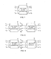
- the block 10 comprises a plurality'of input terminals for receiving N input signals, s 1 s 2 ...,s j ...s N and a plurality of output terminals for providing M output responses P 1 P 2 ...,P 1 ...,P M .
- This device functions to separate incoming patterns into their respective classes. This is accomplished by creating a number of "prototypes" in the manner explained below.
- the pattern class separator may be operated in a "training mode” in which prototypes are formed and modified, and in a “trained mode” in which no training modifications are made to the system.
- this pattern class separator there can be considered a situation in which there are K external classes to be separated and, of course, thereafter identified.
- the K classes may constitute the ten Arabic numerals 0-9 and the twenty six upper and lower case letters A-Z of the Roman alphabet wherein each number of letter constitutes a separate class.
- a simple graphic structure such as the Arabic numeral "7" can be written in many ways and yet be correctly recognisable by a" human reader.
- the pattern class separator of Fig. 1 receives as inputs the representatives of the various different classes. These representatives, before being fed to the pattern class separator are first coded into signals s 1 , s 2 ...,s j ...s N by means of an initial coding scheme which, is designed to preserve information but to remove obvious irrelevant features. In this latter connection, clearly, the better the coding, the easier the class separation but, in accordance with the invention, a rough coding is operative.
- outputs p 1 ,p 2 ...p j ...p M are shown applied to the block 12, legended "pattern class identifier".
- the outputs of pattern class identifier r 1 ,r 2 ...,rl...,r K indicate discrete class identifi-cations.
- output r l for example, could be members of the class constituting all the representatives of the Arabic numeral"0.
- the respective outputs p 1 , p 2 ..,p 1 ...,p M of the pattern class separator indicate the presence of prototypes.
- Fig. 3 wherein there are shown the functional components of pattern class identifier 12, it is seen that: prototype p 1 is applied to a multiple OR circuit 14; prototype p 2 is applied to multiple OR circuit 16; prototype p i is applied to multiple OR circuit 18 and prototype p M is applied to multiple OR circuit 20.
- the outputs of circuits 18, 14, 20 and 16 are r 1 , r 2 , rl and r K , respectively. Each one of the r outputs thus identifies one of the classes by including all the representatives or prototypes belonging to a single class such as an Arabic numeral where the numerals 0 - 9 form ten classes.
- a pattern comes in in the form of a normalized vector and is not recognized, i.e. is not declared “like” or linearly like” a prototype previously stored, it is made into a new prototype.
- the vector representing the pattern (initially of unit length) is "stretched” by multiplication with a positive factor ⁇ ( ⁇ >I) and thus is given a length greater than unity.
- ⁇ positive factor
- a three dimensional space may be considered as a useful example.
- the incoming patterns are represented by three dimensional vectors of unit length emerging from a common origin, which is also the center of a sphere of unit radius.
- Each pattern is identified by a point on the sphere, the end point of the radius - vector representing the pattern.
- Each prototype is also a vector along a radius of the same sphere, but whose length is larger than unity so that a prototype vector extends above the surface of the sphere.
- Such prototypes may also be represented by circles on the surface of the sphere. The circles are centered on the points of emergence of the prototype vectors on the sphere; the diameters of the circles are proportional to the magnitudes of the vectors.
- Each class of patterns is thus represented by one or more prototypes.
- the separation into various classes occurs naturally and is independent of the shape of the boundaries between classes.
- the classes be separable by linear elements (i.e. straight lines, planes, hyper-' planes) as the shape of the boundary is arbitrary.
- the procedure for attempting to recognize an incoming pattern consists of forming the inner (scalar) product between this pattern and all prototypes (which, in principle, is done in parallel). If the inner product equals or exceeds a predetermined value (threshold) the incoming pattern is identified with the class of the corresponding prototype.
- the threshold for recognition (minimum value of the inner product) is linked to the value of ⁇ °, which determines the maximum length of a prototype.
- ⁇ ° determines the maximum diameter of the prototype circle of influence, or equivalently the largest angle of the cone centered on the prototype and thus the incoming patterns furthest removed from the prototype, which can still be identified with this prototype.
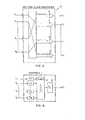
- Fig. 5 there is shown therein the structure constituting pattern class separator 10; in particular, blocks 22, 24, 26 and 28 which represent assembly 1, assembly 2, assembly i and assembly M , respectively.
- the vector s,, s 2 ...s j ...,s N which is the signal coding of a single pattern, is shown as commonly applied to all of the assemblies.
- the outputs of assemblies 1,2...,i...,M produce outputs p 1 ,p 2 ...p i ,..p M , respectively.
- FIG. 7 wherein there is shown a suitable embodiment of an assembly i of Fig. 5 that is employed according to the invention in its training mode of operation.
- the signals of the input vector sl , s 2 ...,s J ...,s M are shown applied to a matrix of weighting stages A il , A i2 ....,A ij ....,AiM.
- the first subscript of an A stage is the same as its assembly descriptor.
- the second subscript is the designator of the particular A stage within a given assembly.
- the members of the A matrix are junction elements, each element effecting a transfer of information from its input terminal j in dependence upon the signal s j , and uppn a "transfer function" A ij of that stage.
- the transfer function may be a simple multiplication by a stored weighting factor.
- the matrix of transfer functions e.g. the weighting factors may be modified in accordance with a particular algorithm.
- the outputs of the 'A' matrix are applied to a block 30 or summer i which effects the addition of these outputs and produces an intermediate output p' i on line 31.
- the summer may be an operational amplifier connected as a summing circuit in an analog embodiment or a digital adder if the signals are presented in digital form.
- Element 35 may be suitably of the operational amplifier type and has an inhibit input to which is applied the output of stage 34, i.e. ⁇ p i , as is further explained hereinbelow whereby the transfer functions are modified.
- Element 35 may also be a gate, such as an AND gate followed by an inverter. Such operation is disclosed in the aforementioned patents and the explanation in connection with such disclosure is incorporated by reference into this application. Suffice it to say that the transfer functions are modified in accordance with the algorithm.
- the output p' i of summer i on line 31 is applied to a stage 32 legended ⁇ i which may suitably be a scalar multiplication unit.
- ⁇ i which may suitably be a scalar multiplication unit.
- the output of the summer is multiplied by a chosen factor.
- the result of such multiplication is applied to a following stage 34 legended ⁇ p.
- the ⁇ pi stage functions as a threshold device. In other words if the output of the ⁇ stage equals or exceeds a chosen level, the 9 stage is actuated.
- a ⁇ stage may suitably be a circuit element, such as a Schmitt trigger in an analog embodiment or a corresponding digital element. which produces an output if the input applied thereto attains the aforementioned level.
- the ⁇ stage is utilised, according to the invention, when the system is in the training mode.
- stage ⁇ pi is applied as an inhibit input to element 35.
- Element 35 is constructed to pass the signal p' i from its input to its output when there is no occurrence of a p i output resulting from the actuation of threshold stage ⁇ pi .
- This structure is provided to prevent the modification of the transfer functions of the 'A' matrix when a ⁇ pi stage is actuated,after the formation of a prototype has been completed.
- FIGURE 8 depicts an illustrative embodiment of a system constructed according to the principles of the invention.
- assembly 1 assembly i..., assembly M
- each assembly having the structure of assembly 26 as disclosed in FIGURE 7.
- the assembly in the top row of FIGURE 8 comprises the 'A' matrix A ll ...,A lj ...A lM , summer ⁇ 1 , lambda stage ⁇ 1 , and threshold stage ⁇ p 1 .
- the assembly in the middle row corn prises like stages designated with the subscript i and the assembly .in the bottom row comprises like stages designated with the subscript M.
- the signal vector s 1 ..., s j ...,s N is applied to all of the assemblies.
- the signals constituting the vector characterise an event. This can be an optical event such as the sight of a pattern, an auditory event such as the hearing of the tone, etc. The only requirement for the event is that it be translatable into a plurality of input signals which retain sufficient detail about the event to permit separation and identification.
- the signals constituting the vector are generated by a translator which performs some form of analysis of the event and produces signals in response to this analysis. For example, (as described in the above reference U.S. Patent No. 3,950,733) the translator may divide a visual scene into raster elements ,perform a Fourier analysis of auditory information, etc. Such translators are well known in the art and no detailed description thereof is deemed necessary.
- the applied signal vector is accordingly processed in each assembly as set forth in connection with the description of the structure and operation of the assembly of FIGURE 7.
- the first signal vector applied to the assemblies of the system results from a translation of a numeral form "0".
- the(initial)values of the elements A ij of the A matrix are random and the probability is small of producing an output p i of the summers, after being multiplied by (the minimum value of the scalar multiplies to which all ⁇ 's are set initially, that is prior to any training operations)and exceeding the threshold ⁇ p i .
- circuit 44 which is enabled ' by the appearance of signals on any two of its three inputs has applied thereto: (1) activated control line 38 and (2) the p 1 output from threshold stage ⁇ pl . Consequently, circuit 44 produces an output which is passed to the R 1 stage 36 to produce an output r l , stage 36 suitably being a multiple OR circuit.
- the output of circuit 44 also sets a flip-flop 46, the permanently set output of flip-flop 46 being fed back as an input to AND circuit 44.
- the training operation suitably continues by consecutively feeding signal vectors designating the members of the various classes, in this example, the class being the numeral "0".
- the transfer functions of the A matrices of the assemblies will be modified until there will be sane assemblies for each member of the class whose ⁇ stage output will be sufficient to trigger the associated ⁇ stage to thereby effect the output from the stage R 1 .
- control line 38 is deactivated as permanent connections have been established between each of the units of the P-bank committed to the class under consideration and the corresponding R-unit.
- the p i output and the signal on line 50 consequently enable and AND circuit 52, this AND circuit being of the same type as the AND circuit 44.
- a flip-flop 54 On receipt of an input, a flip-flop 54 is set and its output is fed back as an input to the AND circuit 52.
- the output of the AND circuit 52 is also supplied to the output stage 48, i.e. R l the output appearing there as output r l .
- a signal vector representing a member of the class "6" may also produce an output from a stage previously committed to another class for example, from ⁇ 1 , i.e. stage 40 sufficient to activate the threshold stage 42, i.e. stage ⁇ pl previously committed to a prototype for a zero.
- the p 1 output from 6 pl , and the set output from flip-flop 46 will enable the AND circuit 44 whereby a signal will appear at the output r 1 of output stage 36, i.e. R 1 , which in this example is dedicated to identifying members of the "0" class. This is clearly an undesired occurrence since it introduces an ambiguity into the class separation and identification.
- a next class is processed.
- this next class comprises representatives of the numeral "9".
- contro line 50 is deactivated and a control line 62 is activated.
- the assembly in the bottom row of FIGURE 8 is one of those where an output is produced from its threshold stage ⁇ pM upon application of a signal vector representing a member of class "9" to the system.
- an AND circuit 63 which is of the same type as AND circuits 44 and 52, is enabled by the application thereto of the p M and line 62 signals. Consequently, a signal is passed through a multiple OR stage 64 to appear as output r K .
- a flip-flop 66 is set, the set output of this flip-flop 66 being applied as an input to AND circuit 63.
- the values of the A matrices and the multiplication factors of the ⁇ stages will be at levels such that there will be substantially no conflict of separation and identification between separate classes.
- the classes comprise the ten numerals "0" to "9" and assuming that there are ten members to each class
- some of the values of the A matrices may also .be modified to such a level.
- sufficient assemblies and their associated logic and circuit elements are readily and cheaply provided.
- the system can also be used to separate ana identify these classes in the trained mode of operation.
- all of the flip-flops are first reset and thecontrol lines are reactivated one by one, in the manner described above, during the operation.
- the inventive system as described insofar as it relates to the "training mode" of operation, it is convenient to regard it as a three-level system comprising an input or signal bank S(s 1 ...,s N ), a first threshold bank P(p 1 ...p M ), and a second threshold or response bank, R(r,...r k ).
- the input bank, S accepts the initial coded signal.
- the first threshold bank, P stores prototypes, while the response bank, R, produces the appropriate responses that identify the separate K classes.
- the scalar multiplication unit ⁇ i multiplies p' i by the value of the multiplication factor in this unit.
- the value of ⁇ i varies between a maximum, ⁇ o , and unity 1 ⁇ ⁇ i ⁇ ⁇ °.
- the output of the i th unit of the P bank after thresholding (the output of assembly i) is then where the threshold function is defined by
- the R bank can be considered as including M summers and M X K "B" elements.
- the output of the k th summer of the R bank is given in general by the expression: while the output of the k th response unit (a stage such as output stages 36, 48 and 64 in Fig. 8) is
- the embodiment including the flip-flops shown in Fig. 8 is a specific example of one of the various simplifications of the R-bank.
- This embodiment illustrates the simplificatior wherein there are employed "On-Off" elements for the B kl term of equation [3]. These elements establish a connection between the outputs of the P-bank and the R-bank when prototypes of classes of events such as pattern classes are being generated.
- the value of the A and B matrices can be set equal to zero; thus there is no response in the P or the R bank to any incaning pattern.
- the first incaning pattern,s l (1) (say one in class 1) produces no response in the P bank and therefore no response in the appropriate unit in the R bank, r i .
- the process of committment can be formally represented by adding to the value of the A matrix where p 1 is a unit vector in the P bank setting the value of ⁇ 1 to its maximum ⁇ 0 and setting to unity the element between ⁇ 1 and r i , B li .
- the initial values of the elements A ij of the A matrix are random and, most likely, sufficiently small to provide a modest probability of producing an output p' i of the summers iri the P bank and after being multiplied by ⁇ 0 i , exceeding the threshold ⁇ pi .
- the process of prototype commitment according to the invention consists of presenting the first incoming event - i.e. pattern s i (1) - repeatedly in order to modify, for each presentation, the values of the matrix elements A ij according to the Nestor modification algorithm (as explained in the aforementioned U.S. Patent No. 3,950,733):
- the pattern is again presented repeatedly until another unit of the P-bank will produce an output sufficient to exceed its threshold ⁇ and a new prototype is formed.
- Another output stage R is then selected to identify the patterns represented by this prototype.
- a connection between the P-unit just committed to this prototype and the last-mentioned R unit is established by closing the appropriate element B (setting the appropriate flip-flcp in the embodinent shown in FIGURE 8).
- a subsequent incoming pattern may cause one or more of the following, thereby resulting in the indicated modification. The following may occur:
- a particular training set of inputs consisting of large numbers of events, i.e. patterns in each of K classes (the number of patterns is not necessarily the same . for each of the K classes) is preferably presented at least twice. This is because the prototypes committed toward the end of the first presentation may not be tested ("challenged") by enough inputs to reduce their magnitudes to values compatible with the nature (characteristics) of all the inputs.
- An entering pattern that is not.identified or not correctly identified becomes a prototype, thereby being stored in the A matrix and firing a particular unit in the P bank and the correct response unit for the class in the R bank.
- Each prototype in the P bank has' a certain hypersphere of influence determined by the value of ⁇ stored in its scalar multiplication unit. The value of ⁇ is reduced every time the prototype responds incorrectly to a signal of the wrong class. It is thus incorrect identifications that shrink the radius of influence of the hypersphere centered at a given prototype.
- prototypes may be required to map out a difficult boundry or regions of the same class separated by regions of another class.
- the number of prototypes required is of course dependent on the efficiency of the original code in producing well-separated clusters. However even badly separated regions will eventually be separated and identified by the system.
- prototypes may sometimes be redundant, it will be evident to those skilled in the art that a variety of modifications may be employed, such as averaging those prototypes which lie within each other's spheres of influence, by which the number of prototypes can be reduced to approach the optimum number or the minimum necessary for satisfactory operation.
- the learning or training mode is terminated (no further modification)and the system is then operated in the trained mode to separate and identify classes.
- the system can be employed in the trained mode.
- the assemblies may take on the structural arrangement shown in Fig. 6.
- Fig. 8 the only structures in Fig. 8 which are required are the output stages (OR circuit 1) such as stages 36, 48 and 64 and direct connections between the outputs p j ,...p i ...p M , and these respective output stages.
- the feedback arranged to X stages, such as AND circuits 58 and 60, are of course eliminated or not used.
- Flip-flops such as 46, 54 and 66 and associated AND gates . 4 4, 52 and 63.are also unnecessary in the trained mode of operation since there is no need to look for undesired outputs, i.e. errors in class identification.
- Fig. 4 shows the structure of a pattern class separator 10 connected to a Nestor adaptive module 74 such as shown in Fig. 3 of the aboye referred to U.S: Patent No. 3,950,733.
- the assemblies of the pattern class separator 10 have the form shown in Fig. 6, i.e. the structural arrangement employed in the trained mode of operation.
- the output of the assemblies, viz,P 1 p 2 ...p i ...,p M are applied as inputs to the Nestor adaptive module.
- the p 1 P 2 ...p i ...,p M outputs of pattern class separator 10 correspond to the s 1 , s 2 ...s j ..., s inputs to the Nestor module as shown in Fig. 3 of the above mentioned patent.
- initial values of the elements of the A matrices can be pre-chosen to control the course of the training.
Landscapes
- Engineering & Computer Science (AREA)
- Data Mining & Analysis (AREA)
- Theoretical Computer Science (AREA)
- Computer Vision & Pattern Recognition (AREA)
- Bioinformatics & Cheminformatics (AREA)
- Bioinformatics & Computational Biology (AREA)
- Artificial Intelligence (AREA)
- Evolutionary Biology (AREA)
- Evolutionary Computation (AREA)
- Physics & Mathematics (AREA)
- General Engineering & Computer Science (AREA)
- General Physics & Mathematics (AREA)
- Life Sciences & Earth Sciences (AREA)
- Image Analysis (AREA)
- Complex Calculations (AREA)
Applications Claiming Priority (2)
| Application Number | Priority Date | Filing Date | Title |
|---|---|---|---|
| US134571 | 1980-03-27 | ||
| US06/134,571 US4326259A (en) | 1980-03-27 | 1980-03-27 | Self organizing general pattern class separator and identifier |
Publications (3)
| Publication Number | Publication Date |
|---|---|
| EP0037164A2 true EP0037164A2 (de) | 1981-10-07 |
| EP0037164A3 EP0037164A3 (en) | 1982-08-04 |
| EP0037164B1 EP0037164B1 (de) | 1986-09-24 |
Family
ID=22463966
Family Applications (1)
| Application Number | Title | Priority Date | Filing Date |
|---|---|---|---|
| EP81300559A Expired EP0037164B1 (de) | 1980-03-27 | 1981-02-11 | Selbstorganisierender Trenner und Identifizierer von allgemeinen Formklassen |
Country Status (7)
| Country | Link |
|---|---|
| US (1) | US4326259A (de) |
| EP (1) | EP0037164B1 (de) |
| JP (1) | JPS56152086A (de) |
| CA (1) | CA1157159A (de) |
| DE (1) | DE3175363D1 (de) |
| ES (1) | ES8202967A1 (de) |
| MX (1) | MX151653A (de) |
Cited By (4)
| Publication number | Priority date | Publication date | Assignee | Title |
|---|---|---|---|---|
| EP0191407A3 (en) * | 1985-02-15 | 1989-11-08 | Nestor, Inc. | Parallel, multi-unit, adaptive, nonlinear pattern class separator and identifier |
| FR2639739A1 (fr) * | 1988-11-25 | 1990-06-01 | Labo Electronique Physique | Procede et dispositif de compression de donnees d'image utilisant un reseau de neurones |
| EP0395150A1 (de) * | 1989-04-26 | 1990-10-31 | Laboratoires D'electronique Philips | Verfahren und Einrichtung zur Datenkompression |
| GB2245401A (en) * | 1989-11-01 | 1992-01-02 | Hughes Aircraft Co | Neural network signal processor |
Families Citing this family (118)
| Publication number | Priority date | Publication date | Assignee | Title |
|---|---|---|---|---|
| DE3026055C2 (de) * | 1980-07-09 | 1984-01-12 | Computer Gesellschaft Konstanz Mbh, 7750 Konstanz | Schaltungsanordnung zur maschinellen Zeichererkennung |
| JPS5987581A (ja) * | 1982-11-06 | 1984-05-21 | ブル−ス・シヨ−ン・バクリ | 自動パタ−ン認識自己組織化回路およびそれを実施するシステム |
| US4658372A (en) * | 1983-05-13 | 1987-04-14 | Fairchild Camera And Instrument Corporation | Scale-space filtering |
| US4648044A (en) * | 1984-06-06 | 1987-03-03 | Teknowledge, Inc. | Basic expert system tool |
| US4803641A (en) * | 1984-06-06 | 1989-02-07 | Tecknowledge, Inc. | Basic expert system tool |
| US4658370A (en) * | 1984-06-07 | 1987-04-14 | Teknowledge, Inc. | Knowledge engineering tool |
| US4660166A (en) * | 1985-01-22 | 1987-04-21 | Bell Telephone Laboratories, Incorporated | Electronic network for collective decision based on large number of connections between signals |
| US5077807A (en) * | 1985-10-10 | 1991-12-31 | Palantir Corp. | Preprocessing means for use in a pattern classification system |
| US5060277A (en) * | 1985-10-10 | 1991-10-22 | Palantir Corporation | Pattern classification means using feature vector regions preconstructed from reference data |
| US4719591A (en) * | 1985-11-07 | 1988-01-12 | American Telephone And Telegraph Company, At&T Bell Labs. | Optimization network for the decomposition of signals |
| WO1987003411A1 (en) * | 1985-11-27 | 1987-06-04 | The Trustees Of Boston University | Pattern encoding system |
| DE3686051T2 (de) * | 1985-11-27 | 1992-12-17 | Univ Boston | Mustererkennungssystem. |
| US4852018A (en) * | 1987-01-07 | 1989-07-25 | Trustees Of Boston University | Massively parellel real-time network architectures for robots capable of self-calibrating their operating parameters through associative learning |
| US4807168A (en) * | 1987-06-10 | 1989-02-21 | The United States Of America As Represented By The Administrator, National Aeronautics And Space Administration | Hybrid analog-digital associative neural network |
| US5014327A (en) * | 1987-06-15 | 1991-05-07 | Digital Equipment Corporation | Parallel associative memory having improved selection and decision mechanisms for recognizing and sorting relevant patterns |
| US4914708A (en) * | 1987-06-19 | 1990-04-03 | Boston University | System for self-organization of stable category recognition codes for analog input patterns |
| US5040230A (en) * | 1988-01-11 | 1991-08-13 | Ezel Incorporated | Associative pattern conversion system and adaptation method thereof |
| US4958375A (en) * | 1988-02-17 | 1990-09-18 | Nestor, Inc. | Parallel, multi-unit, adaptive pattern classification system using inter-unit correlations and an intra-unit class separator methodology |
| US4931868A (en) * | 1988-05-31 | 1990-06-05 | Grumman Aerospace Corporation | Method and apparatus for detecting innovations in a scene |
| US5050095A (en) * | 1988-05-31 | 1991-09-17 | Honeywell Inc. | Neural network auto-associative memory with two rules for varying the weights |
| US4979124A (en) * | 1988-10-05 | 1990-12-18 | Cornell Research Foundation | Adaptive, neural-based signal processor |
| US4930099A (en) * | 1988-10-07 | 1990-05-29 | Hughes Aircraft Company | Wavefront vector correlation processor and method |
| US5003490A (en) * | 1988-10-07 | 1991-03-26 | Hughes Aircraft Company | Neural network signal processor |
| US4914604A (en) * | 1988-10-07 | 1990-04-03 | Hughes Aircraft Company | Processor for analyzing angle-only data |
| US5001631A (en) * | 1988-10-07 | 1991-03-19 | Hughes Aircraft Company | Cellular network assignment processor using randomly triggered adaptive cell thresholds |
| US5093781A (en) * | 1988-10-07 | 1992-03-03 | Hughes Aircraft Company | Cellular network assignment processor using minimum/maximum convergence technique |
| US4920506A (en) * | 1988-10-07 | 1990-04-24 | Hughes Aircraft Company | Ultra-high speed two-dimensional coordinate transform processor |
| US5083285A (en) * | 1988-10-11 | 1992-01-21 | Kabushiki Kaisha Toshiba | Matrix-structured neural network with learning circuitry |
| US5008833A (en) * | 1988-11-18 | 1991-04-16 | California Institute Of Technology | Parallel optoelectronic neural network processors |
| US4912651A (en) * | 1988-12-14 | 1990-03-27 | Gte Laboratories Incorporated | Speeding learning in neural networks |
| US4912655A (en) * | 1988-12-14 | 1990-03-27 | Gte Laboratories Incorporated | Adjusting neural networks |
| US4912654A (en) * | 1988-12-14 | 1990-03-27 | Government Systems Corporation Gte | Neural networks learning method |
| US4912653A (en) * | 1988-12-14 | 1990-03-27 | Gte Laboratories Incorporated | Trainable neural network |
| US4912649A (en) * | 1988-12-14 | 1990-03-27 | Gte Government Systems Corporation | Accelerating learning in neural networks |
| US4912647A (en) * | 1988-12-14 | 1990-03-27 | Gte Laboratories Incorporated | Neural network training tool |
| US4912652A (en) * | 1988-12-14 | 1990-03-27 | Gte Laboratories Incorporated | Fast neural network training |
| US4914603A (en) * | 1988-12-14 | 1990-04-03 | Gte Laboratories Incorporated | Training neural networks |
| US5048100A (en) * | 1988-12-15 | 1991-09-10 | Michael Kuperstein | Self organizing neural network method and system for general classification of patterns |
| US4941122A (en) * | 1989-01-12 | 1990-07-10 | Recognition Equipment Incorp. | Neural network image processing system |
| US4974169A (en) * | 1989-01-18 | 1990-11-27 | Grumman Aerospace Corporation | Neural network with memory cycling |
| US5033020A (en) * | 1989-02-08 | 1991-07-16 | Grumman Aerospace Corporation | Optically controlled information processing system |
| US5222195A (en) * | 1989-05-17 | 1993-06-22 | United States Of America | Dynamically stable associative learning neural system with one fixed weight |
| US5119469A (en) * | 1989-05-17 | 1992-06-02 | United States Of America | Neural network with weight adjustment based on prior history of input signals |
| US5041976A (en) * | 1989-05-18 | 1991-08-20 | Ford Motor Company | Diagnostic system using pattern recognition for electronic automotive control systems |
| JP2940933B2 (ja) * | 1989-05-20 | 1999-08-25 | 株式会社リコー | パターン認識方式 |
| US5339818A (en) * | 1989-09-20 | 1994-08-23 | University Of Utah Research Foundation | Method for determining blood pressure utilizing a neural network |
| US5361328A (en) * | 1989-09-28 | 1994-11-01 | Ezel, Inc. | Data processing system using a neural network |
| US5136687A (en) * | 1989-10-10 | 1992-08-04 | Edelman Gerald M | Categorization automata employing neuronal group selection with reentry |
| JP2724374B2 (ja) * | 1989-10-11 | 1998-03-09 | 株式会社鷹山 | データ処理装置 |
| JP2763182B2 (ja) * | 1990-06-28 | 1998-06-11 | 株式会社東芝 | ニューラル・ネットワークの学習方法 |
| US5181259A (en) * | 1990-09-25 | 1993-01-19 | The United States Of America As Represented By The Administrator Of The National Aeronautics And Space Administration | General method of pattern classification using the two domain theory |
| US5194864A (en) * | 1990-10-03 | 1993-03-16 | Olympus Optical Co., Ltd. | Vector quantization method and apparatus |
| US5239594A (en) * | 1991-02-12 | 1993-08-24 | Mitsubishi Denki Kabushiki Kaisha | Self-organizing pattern classification neural network system |
| JP3088171B2 (ja) * | 1991-02-12 | 2000-09-18 | 三菱電機株式会社 | 自己組織型パタ−ン分類システム及び分類方法 |
| WO1992020029A1 (en) * | 1991-04-29 | 1992-11-12 | Intel Corporation | Neural network incorporating difference neurons |
| US5263120A (en) * | 1991-04-29 | 1993-11-16 | Bickel Michael A | Adaptive fast fuzzy clustering system |
| US5357597A (en) * | 1991-06-24 | 1994-10-18 | International Business Machines Corporation | Convolutional expert neural system (ConExNS) |
| US5963930A (en) * | 1991-06-26 | 1999-10-05 | Ricoh Company Ltd. | Apparatus and method for enhancing transfer function non-linearities in pulse frequency encoded neurons |
| DE4133965A1 (de) * | 1991-10-14 | 1993-04-15 | Standard Elektrik Lorenz Ag | Abstraktor |
| US10361802B1 (en) | 1999-02-01 | 2019-07-23 | Blanding Hovenweep, Llc | Adaptive pattern recognition based control system and method |
| US8352400B2 (en) | 1991-12-23 | 2013-01-08 | Hoffberg Steven M | Adaptive pattern recognition based controller apparatus and method and human-factored interface therefore |
| US5253329A (en) * | 1991-12-26 | 1993-10-12 | The United States Of America As Represented By The Administrator Of The National Aeronautics And Space Administration | Neural network for processing both spatial and temporal data with time based back-propagation |
| US5276771A (en) * | 1991-12-27 | 1994-01-04 | R & D Associates | Rapidly converging projective neural network |
| US5649066A (en) * | 1992-01-03 | 1997-07-15 | The Florida State University For And On Behalf Of The Florida Board Of Regents | Method and apparatus for refinement of learning in expert networks |
| US5438629A (en) * | 1992-06-19 | 1995-08-01 | United Parcel Service Of America, Inc. | Method and apparatus for input classification using non-spherical neurons |
| EP0574937B1 (de) * | 1992-06-19 | 2000-08-16 | United Parcel Service Of America, Inc. | Verfahren und Vorrichtung zur Eingabeklassifizierung mit einem neuronalen Netzwerk |
| GB9214514D0 (en) * | 1992-07-08 | 1992-08-19 | Massachusetts Inst Technology | Information processing |
| US5479574A (en) * | 1993-04-01 | 1995-12-26 | Nestor, Inc. | Method and apparatus for adaptive classification |
| US5537488A (en) * | 1993-09-16 | 1996-07-16 | Massachusetts Institute Of Technology | Pattern recognition system with statistical classification |
| US5524176A (en) * | 1993-10-19 | 1996-06-04 | Daido Steel Co., Ltd. | Fuzzy expert system learning network |
| US6167390A (en) * | 1993-12-08 | 2000-12-26 | 3M Innovative Properties Company | Facet classification neural network |
| US7222079B1 (en) * | 1994-06-23 | 2007-05-22 | Ingenix, Inc. | Method and system for generating statistically-based medical provider utilization profiles |
| US5557514A (en) | 1994-06-23 | 1996-09-17 | Medicode, Inc. | Method and system for generating statistically-based medical provider utilization profiles |
| DE69430527T2 (de) * | 1994-07-28 | 2003-01-02 | International Business Machines Corp., Armonk | Schaltung für das Vorladen von Eingangsvektorbestandteilen in eine freie Neuronalschaltung während der Erkennungsphase |
| EP0694852B1 (de) * | 1994-07-28 | 2002-06-26 | International Business Machines Corporation | Innovative Neuronalschaltungsarchitektur |
| DE69430744T2 (de) * | 1994-07-28 | 2003-01-30 | International Business Machines Corp., Armonk | Verbesserte Neuronalhalbleiterchipsarchitekturen und Neuronalnetzwerke darin |
| WO1997030400A1 (en) * | 1996-02-02 | 1997-08-21 | Rodney Michael John Cotterill | A method of processing data flows in a neural network, and a neural network |
| US6726684B1 (en) * | 1996-07-16 | 2004-04-27 | Arthrocare Corporation | Methods for electrosurgical spine surgery |
| US5742741A (en) * | 1996-07-18 | 1998-04-21 | Industrial Technology Research Institute | Reconfigurable neural network |
| US5751913A (en) * | 1996-07-29 | 1998-05-12 | Industrial Technology Research Institute | Reconfigurable neural network and difference-square neuron |
| GB2321362A (en) * | 1997-01-21 | 1998-07-22 | Northern Telecom Ltd | Generic processing capability |
| US6018723A (en) * | 1997-05-27 | 2000-01-25 | Visa International Service Association | Method and apparatus for pattern generation |
| US6119103A (en) * | 1997-05-27 | 2000-09-12 | Visa International Service Association | Financial risk prediction systems and methods therefor |
| US6097834A (en) * | 1997-06-13 | 2000-08-01 | Paystation America Inc. | Financial transaction processing systems and methods |
| US7403922B1 (en) | 1997-07-28 | 2008-07-22 | Cybersource Corporation | Method and apparatus for evaluating fraud risk in an electronic commerce transaction |
| US7096192B1 (en) * | 1997-07-28 | 2006-08-22 | Cybersource Corporation | Method and system for detecting fraud in a credit card transaction over a computer network |
| US6052679A (en) * | 1997-09-11 | 2000-04-18 | International Business Machines Corporation | Artificial neural networks including Boolean-complete compartments |
| US6560360B1 (en) * | 1999-01-28 | 2003-05-06 | Nestor, Inc. | Feed forward feed back multiple neural network with context driven recognition |
| US8364136B2 (en) | 1999-02-01 | 2013-01-29 | Steven M Hoffberg | Mobile system, a method of operating mobile system and a non-transitory computer readable medium for a programmable control of a mobile system |
| US7966078B2 (en) * | 1999-02-01 | 2011-06-21 | Steven Hoffberg | Network media appliance system and method |
| RU2189078C2 (ru) * | 1999-10-01 | 2002-09-10 | Дальневосточный государственный технический университет | Способ обработки сигналов |
| US6999943B1 (en) | 2000-03-10 | 2006-02-14 | Doublecredit.Com, Inc. | Routing methods and systems for increasing payment transaction volume and profitability |
| US6904408B1 (en) * | 2000-10-19 | 2005-06-07 | Mccarthy John | Bionet method, system and personalized web content manager responsive to browser viewers' psychological preferences, behavioral responses and physiological stress indicators |
| US8209246B2 (en) | 2001-03-20 | 2012-06-26 | Goldman, Sachs & Co. | Proprietary risk management clearinghouse |
| US8140415B2 (en) | 2001-03-20 | 2012-03-20 | Goldman Sachs & Co. | Automated global risk management |
| US20040006532A1 (en) * | 2001-03-20 | 2004-01-08 | David Lawrence | Network access risk management |
| US7904361B2 (en) * | 2001-03-20 | 2011-03-08 | Goldman Sachs & Co. | Risk management customer registry |
| US7899722B1 (en) | 2001-03-20 | 2011-03-01 | Goldman Sachs & Co. | Correspondent bank registry |
| US20020138417A1 (en) * | 2001-03-20 | 2002-09-26 | David Lawrence | Risk management clearinghouse |
| US8069105B2 (en) * | 2001-03-20 | 2011-11-29 | Goldman Sachs & Co. | Hedge fund risk management |
| US7548883B2 (en) * | 2001-03-20 | 2009-06-16 | Goldman Sachs & Co | Construction industry risk management clearinghouse |
| US7958027B2 (en) * | 2001-03-20 | 2011-06-07 | Goldman, Sachs & Co. | Systems and methods for managing risk associated with a geo-political area |
| US8285615B2 (en) | 2001-03-20 | 2012-10-09 | Goldman, Sachs & Co. | Construction industry risk management clearinghouse |
| US8121937B2 (en) | 2001-03-20 | 2012-02-21 | Goldman Sachs & Co. | Gaming industry risk management clearinghouse |
| US7865427B2 (en) | 2001-05-30 | 2011-01-04 | Cybersource Corporation | Method and apparatus for evaluating fraud risk in an electronic commerce transaction |
| US6975996B2 (en) * | 2001-10-09 | 2005-12-13 | Goldman, Sachs & Co. | Electronic subpoena service |
| EP1461754A4 (de) * | 2001-11-28 | 2005-11-09 | Goldman Sachs & Co | Transaktionsüberwachung |
| US7702574B2 (en) * | 2002-11-14 | 2010-04-20 | Goldman Sachs & Co. | Independent research consensus earnings estimates and methods of determining such |
| US8340981B1 (en) | 2004-03-02 | 2012-12-25 | Cave Consulting Group, Inc. | Method, system, and computer program product for physician efficiency measurement and patient health risk stratification utilizing variable windows for episode creation |
| US8082207B2 (en) * | 2004-06-17 | 2011-12-20 | Certegy Check Services, Inc. | Scored negative file system and method |
| US8996481B2 (en) | 2004-07-02 | 2015-03-31 | Goldman, Sach & Co. | Method, system, apparatus, program code and means for identifying and extracting information |
| US8442953B2 (en) | 2004-07-02 | 2013-05-14 | Goldman, Sachs & Co. | Method, system, apparatus, program code and means for determining a redundancy of information |
| US8762191B2 (en) | 2004-07-02 | 2014-06-24 | Goldman, Sachs & Co. | Systems, methods, apparatus, and schema for storing, managing and retrieving information |
| US8510300B2 (en) | 2004-07-02 | 2013-08-13 | Goldman, Sachs & Co. | Systems and methods for managing information associated with legal, compliance and regulatory risk |
| JP5533662B2 (ja) * | 2008-10-30 | 2014-06-25 | コニカミノルタ株式会社 | 情報処理装置 |
| US8683620B1 (en) * | 2009-04-29 | 2014-04-01 | John F. Krumme | Pool covers |
| US9965208B1 (en) | 2012-02-23 | 2018-05-08 | Micron Technology, Inc. | Memory device having a controller to enable and disable mode control circuitry of the controller |
| US10133151B2 (en) | 2017-02-23 | 2018-11-20 | International Business Machines Corporation | Media-defined optical logic circuitry design |
Family Cites Families (6)
| Publication number | Priority date | Publication date | Assignee | Title |
|---|---|---|---|---|
| DE1549923A1 (de) * | 1967-08-04 | 1971-05-13 | Telefunken Patent | Auswerteeinrichtung fuer zeichenlesende Maschinen |
| US3601811A (en) * | 1967-12-18 | 1971-08-24 | Matsushita Electric Industrial Co Ltd | Learning machine |
| FR2051725B1 (de) * | 1969-07-14 | 1973-04-27 | Matsushita Electric Industrial Co Ltd | |
| US3810162A (en) * | 1970-06-01 | 1974-05-07 | Texas Instruments Inc | Nonlinear classification recognition system |
| US3950733A (en) * | 1974-06-06 | 1976-04-13 | Nestor Associates | Information processing system |
| US4044243A (en) * | 1976-07-23 | 1977-08-23 | Nestor Associates | Information processing system |
-
1980
- 1980-03-27 US US06/134,571 patent/US4326259A/en not_active Expired - Lifetime
-
1981
- 1981-02-04 CA CA000370098A patent/CA1157159A/en not_active Expired
- 1981-02-11 EP EP81300559A patent/EP0037164B1/de not_active Expired
- 1981-02-11 DE DE8181300559T patent/DE3175363D1/de not_active Expired
- 1981-03-13 JP JP3641281A patent/JPS56152086A/ja active Granted
- 1981-03-25 ES ES500677A patent/ES8202967A1/es not_active Expired
- 1981-03-27 MX MX186590A patent/MX151653A/es unknown
Cited By (6)
| Publication number | Priority date | Publication date | Assignee | Title |
|---|---|---|---|---|
| EP0191407A3 (en) * | 1985-02-15 | 1989-11-08 | Nestor, Inc. | Parallel, multi-unit, adaptive, nonlinear pattern class separator and identifier |
| FR2639739A1 (fr) * | 1988-11-25 | 1990-06-01 | Labo Electronique Physique | Procede et dispositif de compression de donnees d'image utilisant un reseau de neurones |
| EP0372608A1 (de) * | 1988-11-25 | 1990-06-13 | Laboratoires D'electronique Philips | Verfahren und Einrichtung zur Bilddatenkompression mit einem neuronalen Netzwerk |
| EP0395150A1 (de) * | 1989-04-26 | 1990-10-31 | Laboratoires D'electronique Philips | Verfahren und Einrichtung zur Datenkompression |
| FR2646575A1 (fr) * | 1989-04-26 | 1990-11-02 | Labo Electronique Physique | Procede et structure pour la compression de donnees |
| GB2245401A (en) * | 1989-11-01 | 1992-01-02 | Hughes Aircraft Co | Neural network signal processor |
Also Published As
| Publication number | Publication date |
|---|---|
| DE3175363D1 (en) | 1986-10-30 |
| ES500677A0 (es) | 1982-03-01 |
| JPS56152086A (en) | 1981-11-25 |
| US4326259A (en) | 1982-04-20 |
| ES8202967A1 (es) | 1982-03-01 |
| CA1157159A (en) | 1983-11-15 |
| JPS6355106B2 (de) | 1988-11-01 |
| EP0037164B1 (de) | 1986-09-24 |
| EP0037164A3 (en) | 1982-08-04 |
| MX151653A (es) | 1985-01-25 |
Similar Documents
| Publication | Publication Date | Title |
|---|---|---|
| EP0037164B1 (de) | Selbstorganisierender Trenner und Identifizierer von allgemeinen Formklassen | |
| US5299284A (en) | Pattern classification using linear programming | |
| De Jong et al. | An analysis of the interacting roles of population size and crossover in genetic algorithms | |
| Zeng et al. | Discrete recurrent neural networks for grammatical inference | |
| CN114444476B (zh) | 信息处理方法、装置和计算机可读存储介质 | |
| WO2022052468A1 (en) | Methods and systems for product quantization-based compression of matrix | |
| EP0036150A2 (de) | System zur Mustererkennung nach dem Mehrfach-Ähnlichkeitsverfahren | |
| Sloan Jr | Dynamically Quantized Pyramids. | |
| US5528700A (en) | Character recognition system based on a neural network | |
| CN113919333A (zh) | 基于知识图谱的文本知识补充方法及装置 | |
| KR0172197B1 (ko) | 정보 처리 방법 및 장치 | |
| CN105740786A (zh) | 书写人的身份识别方法及装置 | |
| Ali et al. | Hybrid Arabic handwritten character recognition using PCA and ANFIS | |
| US5245697A (en) | Neural network processing apparatus for identifying an unknown image pattern as one of a plurality of instruction image patterns | |
| CN111602145A (zh) | 卷积神经网络的优化方法及相关产品 | |
| CN113392868A (zh) | 一种模型训练的方法、相关装置、设备及存储介质 | |
| Bagde et al. | A handwritten recognition for free style Marathi script using genetic algorithm | |
| US5712959A (en) | Neural network architecture for non-Gaussian components of a mixture density function | |
| Yan | Color map image segmentation using optimized nearest neighbor classifiers | |
| Shimura | Multicategory learning classifiers for character reading | |
| Obradovic et al. | Unsupervised learning for blind source separation: an information-theoretic approach | |
| Owens et al. | A multi-output-layer perceptron | |
| Rahman et al. | Recognition of handwritten characters with a multi-expert system | |
| KR100200871B1 (ko) | 이항 인식에 기반한 문자 인식 방법 및 장치 | |
| Bebis et al. | Increasing classification accuracy using multiple-neural-network schemes |
Legal Events
| Date | Code | Title | Description |
|---|---|---|---|
| PUAI | Public reference made under article 153(3) epc to a published international application that has entered the european phase |
Free format text: ORIGINAL CODE: 0009012 |
|
| AK | Designated contracting states |
Designated state(s): CH DE FR GB IT LI NL |
|
| PUAL | Search report despatched |
Free format text: ORIGINAL CODE: 0009013 |
|
| 17P | Request for examination filed |
Effective date: 19820331 |
|
| AK | Designated contracting states |
Designated state(s): CH DE FR GB IT LI NL |
|
| RAP1 | Party data changed (applicant data changed or rights of an application transferred) |
Owner name: NESTOR, INC. |
|
| ITF | It: translation for a ep patent filed | ||
| RAP1 | Party data changed (applicant data changed or rights of an application transferred) |
Owner name: NESTOR, INC. |
|
| GRAA | (expected) grant |
Free format text: ORIGINAL CODE: 0009210 |
|
| AK | Designated contracting states |
Kind code of ref document: B1 Designated state(s): CH DE FR GB IT LI NL |
|
| REF | Corresponds to: |
Ref document number: 3175363 Country of ref document: DE Date of ref document: 19861030 |
|
| ET | Fr: translation filed | ||
| PLBE | No opposition filed within time limit |
Free format text: ORIGINAL CODE: 0009261 |
|
| STAA | Information on the status of an ep patent application or granted ep patent |
Free format text: STATUS: NO OPPOSITION FILED WITHIN TIME LIMIT |
|
| 26N | No opposition filed | ||
| PG25 | Lapsed in a contracting state [announced via postgrant information from national office to epo] |
Ref country code: FR Free format text: LAPSE BECAUSE OF NON-PAYMENT OF DUE FEES Effective date: 19871030 |
|
| REG | Reference to a national code |
Ref country code: FR Ref legal event code: ST |
|
| PGFP | Annual fee paid to national office [announced via postgrant information from national office to epo] |
Ref country code: FR Payment date: 19910117 Year of fee payment: 11 |
|
| ITTA | It: last paid annual fee | ||
| PGFP | Annual fee paid to national office [announced via postgrant information from national office to epo] |
Ref country code: DE Payment date: 19980603 Year of fee payment: 18 |
|
| PGFP | Annual fee paid to national office [announced via postgrant information from national office to epo] |
Ref country code: GB Payment date: 19990115 Year of fee payment: 19 |
|
| PG25 | Lapsed in a contracting state [announced via postgrant information from national office to epo] |
Ref country code: DE Free format text: LAPSE BECAUSE OF NON-PAYMENT OF DUE FEES Effective date: 19991201 |
|
| PGFP | Annual fee paid to national office [announced via postgrant information from national office to epo] |
Ref country code: CH Payment date: 20000203 Year of fee payment: 20 |
|
| PG25 | Lapsed in a contracting state [announced via postgrant information from national office to epo] |
Ref country code: GB Free format text: LAPSE BECAUSE OF NON-PAYMENT OF DUE FEES Effective date: 20000211 |
|
| PGFP | Annual fee paid to national office [announced via postgrant information from national office to epo] |
Ref country code: NL Payment date: 20000225 Year of fee payment: 20 |
|
| GBPC | Gb: european patent ceased through non-payment of renewal fee |
Effective date: 20000211 |
|
| PG25 | Lapsed in a contracting state [announced via postgrant information from national office to epo] |
Ref country code: LI Free format text: LAPSE BECAUSE OF EXPIRATION OF PROTECTION Effective date: 20010210 Ref country code: CH Free format text: LAPSE BECAUSE OF EXPIRATION OF PROTECTION Effective date: 20010210 |
|
| PG25 | Lapsed in a contracting state [announced via postgrant information from national office to epo] |
Ref country code: NL Free format text: LAPSE BECAUSE OF EXPIRATION OF PROTECTION Effective date: 20010211 |
|
| REG | Reference to a national code |
Ref country code: CH Ref legal event code: PL |
|
| NLV7 | Nl: ceased due to reaching the maximum lifetime of a patent |
Effective date: 20010211 |