EP0037384A1 - Soupape à siège à haute pression - Google Patents
Soupape à siège à haute pression Download PDFInfo
- Publication number
- EP0037384A1 EP0037384A1 EP81850052A EP81850052A EP0037384A1 EP 0037384 A1 EP0037384 A1 EP 0037384A1 EP 81850052 A EP81850052 A EP 81850052A EP 81850052 A EP81850052 A EP 81850052A EP 0037384 A1 EP0037384 A1 EP 0037384A1
- Authority
- EP
- European Patent Office
- Prior art keywords
- valve
- control
- seat
- flow
- valve body
- Prior art date
- Legal status (The legal status is an assumption and is not a legal conclusion. Google has not performed a legal analysis and makes no representation as to the accuracy of the status listed.)
- Withdrawn
Links
- 230000002093 peripheral effect Effects 0.000 claims abstract description 5
- 239000012530 fluid Substances 0.000 description 5
- 230000033001 locomotion Effects 0.000 description 4
- 230000001419 dependent effect Effects 0.000 description 3
- 238000004519 manufacturing process Methods 0.000 description 2
- 230000003321 amplification Effects 0.000 description 1
- 230000033228 biological regulation Effects 0.000 description 1
- 230000005540 biological transmission Effects 0.000 description 1
- 238000001514 detection method Methods 0.000 description 1
- 238000004090 dissolution Methods 0.000 description 1
- 230000002706 hydrostatic effect Effects 0.000 description 1
- 230000006698 induction Effects 0.000 description 1
- 238000000034 method Methods 0.000 description 1
- 238000003199 nucleic acid amplification method Methods 0.000 description 1
- 239000007787 solid Substances 0.000 description 1
Images


Classifications
-
- F—MECHANICAL ENGINEERING; LIGHTING; HEATING; WEAPONS; BLASTING
- F16—ENGINEERING ELEMENTS AND UNITS; GENERAL MEASURES FOR PRODUCING AND MAINTAINING EFFECTIVE FUNCTIONING OF MACHINES OR INSTALLATIONS; THERMAL INSULATION IN GENERAL
- F16K—VALVES; TAPS; COCKS; ACTUATING-FLOATS; DEVICES FOR VENTING OR AERATING
- F16K31/00—Actuating devices; Operating means; Releasing devices
- F16K31/12—Actuating devices; Operating means; Releasing devices actuated by fluid
- F16K31/36—Actuating devices; Operating means; Releasing devices actuated by fluid in which fluid from the circuit is constantly supplied to the fluid motor
- F16K31/40—Actuating devices; Operating means; Releasing devices actuated by fluid in which fluid from the circuit is constantly supplied to the fluid motor with electrically-actuated member in the discharge of the motor
-
- F—MECHANICAL ENGINEERING; LIGHTING; HEATING; WEAPONS; BLASTING
- F16—ENGINEERING ELEMENTS AND UNITS; GENERAL MEASURES FOR PRODUCING AND MAINTAINING EFFECTIVE FUNCTIONING OF MACHINES OR INSTALLATIONS; THERMAL INSULATION IN GENERAL
- F16K—VALVES; TAPS; COCKS; ACTUATING-FLOATS; DEVICES FOR VENTING OR AERATING
- F16K31/00—Actuating devices; Operating means; Releasing devices
- F16K31/12—Actuating devices; Operating means; Releasing devices actuated by fluid
- F16K31/36—Actuating devices; Operating means; Releasing devices actuated by fluid in which fluid from the circuit is constantly supplied to the fluid motor
- F16K31/38—Actuating devices; Operating means; Releasing devices actuated by fluid in which fluid from the circuit is constantly supplied to the fluid motor in which the fluid works directly on both sides of the fluid motor, one side being connected by means of a restricted passage and the motor being actuated by operating a discharge from that side
- F16K31/383—Actuating devices; Operating means; Releasing devices actuated by fluid in which fluid from the circuit is constantly supplied to the fluid motor in which the fluid works directly on both sides of the fluid motor, one side being connected by means of a restricted passage and the motor being actuated by operating a discharge from that side the fluid acting on a piston
Definitions
- the present invention refers to a seat valve particularly for high pressures and comprising a valve housing having a main flow passage with a valve seat therein, a valve body being resiliently biased against said seat, and at least one passage for a control flow to a control unit, said control flow being branched-off from the main flow, the control unit being adapted to control the control flow and to control by means of a control member located in the main flow passage also the main flow as a function of the control flow by continuous variation of the position of the valve body between closed and fully open position, the valve seat furthermore being surrounded by a cylindrical wall spaced radially outwardly of the seat and extending axially away therefrom, within which wall the valve body formed as a piston is closely slidably mounted and the control member comprises at least one connecting passage in the cylindrical wall and/or in the peripheral surface of the piston.
- seat valves most often have been controlled by means of fluid pressures, so-called pilot pressures, and have then been controllable only on-off, i.e. to fully closed or fully opened position.
- pilot pressures For providing a continuous control of a flow other common types of valves therefore have been required, such as slide valves, which suffer, however, from the drawback of internal leakage.
- Seat valves are being used more and more, however, i.a. as elements in directional control valves.
- the advantages of seat valves is the freedom from leakages and the fact that the closing-opening sequences easily can be changed.
- the seat valve is continuously controlled by means of electronic equipment and a servo valve.
- the position of the valve body is detected by an induction position-sensing means and compared with a predetermined nominal value in an amplifier. A differential between said values will adjust the servo valve such that equilibrium finally is obtained.
- the greatest drawback of said valve is the fact that the same is very complicated in its structure and hence i.a. liable to disturbances and expensive.
- the main object of the present invention thus is to provide a valve suitable for such high hydraulic pressures.
- This object is obtained by means of a seat valve distinguished in that the connecting passage extends between the input . connection of the valve and the space located at the piston end remote from the valve seat and forms a restricting opening, the through-flow area of which increases with increasing distance of the valve body from the valve seat.
- the main advantage of this arrangement is that it is obtained a self--adjustment of the valve body corresponding to variations of the flow through the control unit.
- the inventive valve also has a plurality of advantages. First of all, it is responsive and reliable and easy to manufacture. It is versatile in use and can be utilized for most fluids including air. Further advantages will be evident from the following detail disclosure.
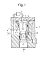
- Fig 1 is a diagrammatical side elevation of a first embodiment of the valve according to the invention
- Fig 2 is a similar view in which, however, the external control unit has the form of a variable restriction
- Fig 3 is a cross-sectional side elevation of a valve according to the invention designed for the opposite direction of a flow and with an external control unit in the form of a small-rate constant flow valve
- Fig 4 is a sectional side elevation of a further embodiment of the invention adapted for the same reversed main flow direction as the valve according to Fig 3 but according to another embodiment and also with another embodiment of a control unit in the form of a constant flow valve
- Fig 5 is a diagrammatical view of how two valves according to the invention can be connected in order to form a directional valve for control of for instance the movement of a single-acting pressure cylinder
- Fig 6 is a diagrammatical view of how four valves according to the invention are to be connected for the control of
- a seat valve according to the invention comprises a valve housing 1 having a main flow passage 2 for a main flow in the direction of the arrows A. Between an input connection 2a and an output connection 2b is located in said main flow passage 2 a valve seat 3 and a valve body or cone 4 is resiliently biased against said seat. Furthermore there is a passage 5 for a control flow to a control unit 7, here located outside the valve housing 1, the control flow being branched-off from the main flow. Said passage 5 comprises a cavity within the valve body, said cavity extending from the end of the valve body 4 adjacent the seat and by means of at least one connecting passage 6 connected to the chamber which is located at the end of the valve body remote from the valve seat and further leads to the control unit 7.
- valve seat 3 is formed with a surrounding cylindrical wall 8 spaced radially outwardly of the seat.
- Said wall 8 extends axially away from the seat 3 and within the wall 8 the valve body made as a cylindrical piston 4 is slidably mounted with a close fit to the wall 8.
- the wall 8 is closely adjacent the seat 3 located at least one opening 10 for connection with the output portion 2b of the passage 2.
- the connecting passage 6 is arranged and made such that it forms a restriction, the through-flow area of which increases with increasing distance of the valve body 4 from the seat 3.
- the connecting passage has been made as two diametrically opposing ports with axial oblong shape and extending from the internal cavity 5 to the peripheral surface of the piston 4.
- the oblong ports 6 are spaced from the surface of the valve body 4, which is adapted to engage the seat 3 such that the end of the ports 6 remote from said surface lie somewhat beyond a step or outermost radial end edge of the cylindrical wall 8 surrounding the piston 4.
- a small connection for pressure fluid from the main flow passage 2 to the control unit 7 thus always will be present.
- control unit 7 As soon as the control unit 7 is actuated for admitting a control flow, pressure fluid flows through the restricted connecting passage 6 and the valve body 4 will be raised from the seat 3 as much as required for establishing equilibrium between the pressure in the chamber 5, which pressure acts in a closing direction on the valve body 4, and the fluid pressure in the passage 2.
- valve In the valve according to the invention the main flow through the passage 2 thus will be a copy of the control flow through the control unit 7, however at a correspondingly larger scale dependent on the area differential between the control flow and main flow passages. Therefore, the valve can be considered as a flow amplifier.
- the valve In the opposite direction of flow to the one illustrated in Fig 1 the valve is capable of freely admitting flow past the valve body 4. This is an advantage in many practical connections. Since the valve body 4 does not either need to be mechanically biased against the seat 3 by means of a return spring or the like the pressure drop in backwards direction can be made small which is of great importance if there are risks for cavitation.
- valve according to the invention can be said to copy the flow characteristics of the control unit 7 by an amplification coefficient independent of the kind of characteristics.
- Fig 2 it is thus shown a valve having the same direction of flow as in Fig 1 but with the valve body 4 illustrated in a position turned 90° relative said figure, the valve body furthermore being illustrated in a longitudinal section.
- the control unit 7 consists of a common variable restriction or orifice and this means that the valve as a whole will behave as such a restriction.
- An advantage of the valve according to the invention is that since only a small portion of the total flow passes through the control unit 7, the adjustment forces on said unit can be made small. This implies that the valve as a whole may be controlled by small forces and therefore it can easily be remote controlled, for instance by means of an electric signal such as indicated.
- FIG. 3 Another embodiment of the valve according to the invention is shown in Fig 3 and is adapted for a main flow in opposite direction to the one illustrated in Figs 1 and 2.
- the valve body 4 now is made solid, i.e. without any internal cavity 5 and the connecting passage 6 is not constituted by ports in this case but by at least one longitudinal slot or groove in the peripheral surface of the piston 5.
- control unit 7 has been illustrated as a small constant flow valve for small flow rates, a pressure reduction valve maintaining a constant pressure through a variable restriction. Hence the valve as a whole will operate as a constant flow valve for great flows.
- control unit 7 has been illustrated as a constant flow valve although having another structural design than in the control unit 7 of Fig 3.
- the pressure drop over the stationary restriction and hence the flow is adjustable by means of the position of the control piston. Similar to the variable restriction said control unit easily can be designed for electric remote control.
- the valve body 4 also has the same design as according to said last-mentioned figure but has been illustrated in a posi- . tion turned 90° relative to Fig 3 and in a longitudinal section.
- a directional valve action in a control of a single-acting pressure cylinder can be obtained by means of two valves.
- two valves are required, namely one for raising movements and one for lowering movements.
- the two valves are controllable by means of variable restrictions and therefore the speed can be continuously varied in both directions. Should said valves be substituted by constant flow valves, a load-independent speed control may be obtained.
- the directional valve of Fig 5 also is equipped with a pressure limitation pilot which provides the valve with a pressure limitation action which protects the cylinder against excessive pressures. The pressure limitation pilot detects the pressure of the cylinder connection while controlling the flow through the valve.
- a double-acting cylinder is to be controlled, four valves according to the invention are required and how said valves are arranged and cooperate has been further illustrated in Fig 6, however, only by means of symbols.
- the directional valve is provided with pressure limitation valves for protection of the cylinder against excessive pressures. Owing to the action of the valve as a check valve in the backward direction an anti-cavitation action in the backward, direction is automatically obtained. This is an advantage which is particularly apparent when controlling rotating machines.
- the check valve of the pump conduit prevents an unintentional lowering motion of the cylinder when the pump fails although the valve also can be closed without pump pressure.
- the check valve is also required when a protection against hose ruptures is desired.
- the valve according to the invention can be modified in many ways within the scope of the accompanying claims.
- the connecting passage 6 need not necessarily be arranged in the valve body or only therein but can be wholly or partially arranged in the cylinder wall 8.
- the passage serves its purpose to connect the control unit 7 with the input connection 2a of the main flow passage 2 and that the passage acts as a restriction with an area of flow increasing with increasing distance of the valve body 4 from the seat 3.
- Figs 1-4 of the drawing the valve has been illustrated in a so-called "cartridge" shape now common in the modern hydraulic control technology.
- the cylinder wall 8 is formed on the inner surface of a cylindric sleeve 9, which is slidable into a corresponding cavity in the valve housing 1 while being sealed by means of e.g. 0-rings.
- the seat 3 is formed and therefore the valve becomes easy to maintain and exchange.
- the cartridge embodiment also allows mounting of the valve in series in one and the same valve housing.
- a particularly interesting advantage of the valve according to the invention is that it is far much more suitable for digital control than prior seat valves.
- Many components of hydrostatic transmissions are namely today controlled electrically or electro-hydraulically and the control signals usually are analog signals.
- the digital technology affords a number of advantages, i.a. in that unique possibilities are given for optimizing control processes. Detection of operation conditions also can be made in a much more rational manner than when using only analog technology.
- the electro-hydraulic signal transducers of systems controlled by micro processors must be adapted to the digital control technology.
- a number of solenoid--controlled valves 7 1-V have throw-flow areas selected in predetermined mutual relationship dependent on the desired spacing between the control steps or "dissolution power" and each such valve controls its corresponding main valve, said main valves also having correspondingly selected mutual relationships between the areas of throw-flow.
- Said type of digital valves most often can be directly (through power transistors) connected to the output of a computer.
- the valves are reliable and relatively fast but for a greater number of control steps they become big and unhandy due to the corresponding increase of the number of great main valves.
- the opening and closing times are dependent of the spring force of the main valve and are short times required, the spring force must be great. This gives rise to a great pressure drop over the valve.
- Fig 7b of the drawing it has been illustrated an example of a corresponding arrangement of a digital control by means of one single valve according to the invention which then in itself simultaneously replaces all the main valves otherwise needed.
- This single main valve is controlled by a number of control units 7A-7E, which number is required for providing the necessary spacing between the control steps.
- a suitable number may be five, as illustrated, which provides for a distance between the control steps of about 3 per cent.
Landscapes
- Engineering & Computer Science (AREA)
- General Engineering & Computer Science (AREA)
- Mechanical Engineering (AREA)
- Fluid-Driven Valves (AREA)
- Lift Valve (AREA)
Applications Claiming Priority (2)
| Application Number | Priority Date | Filing Date | Title |
|---|---|---|---|
| SE8002424 | 1980-03-28 | ||
| SE8002424 | 1980-03-28 |
Publications (1)
| Publication Number | Publication Date |
|---|---|
| EP0037384A1 true EP0037384A1 (fr) | 1981-10-07 |
Family
ID=20340637
Family Applications (1)
| Application Number | Title | Priority Date | Filing Date |
|---|---|---|---|
| EP81850052A Withdrawn EP0037384A1 (fr) | 1980-03-28 | 1981-03-24 | Soupape à siège à haute pression |
Country Status (3)
| Country | Link |
|---|---|
| EP (1) | EP0037384A1 (fr) |
| DD (1) | DD157724A5 (fr) |
| WO (1) | WO1981002771A1 (fr) |
Cited By (3)
| Publication number | Priority date | Publication date | Assignee | Title |
|---|---|---|---|---|
| EP0274833A3 (fr) * | 1987-01-13 | 1989-07-26 | LUCAS INDUSTRIES public limited company | Servo système actionné par fluide |
| EP0487919A1 (fr) * | 1990-11-26 | 1992-06-03 | Leybold Aktiengesellschaft | Appareil détecteur de fuites |
| WO2010033119A1 (fr) | 2008-09-19 | 2010-03-25 | Kiddie-Fenwal, Inc. | Vanne de distribution et procédé de distribution d'un fluide sous pression |
Citations (7)
| Publication number | Priority date | Publication date | Assignee | Title |
|---|---|---|---|---|
| DE262224C (fr) * | ||||
| DE241913C (fr) * | ||||
| DE179157C (fr) * | ||||
| DE241930C (fr) * | ||||
| DE1804858B1 (de) * | 1968-10-24 | 1970-03-26 | Danfoss As | Hilfsgesteuertes Ventil mit Handbetaetigung |
| DE2252543A1 (de) * | 1972-10-26 | 1974-05-02 | Chwoschnjanskij | Regelventil mit impulsbetaetigung |
| SE367242B (fr) * | 1969-08-29 | 1974-05-20 | Hayday Valve And Equip Co Pty |
Family Cites Families (4)
| Publication number | Priority date | Publication date | Assignee | Title |
|---|---|---|---|---|
| US3106934A (en) * | 1958-12-24 | 1963-10-15 | Bendix Corp | Integrating and proportional flow control apparatus |
| US3556468A (en) * | 1967-03-09 | 1971-01-19 | Pall Corp | Unloading valve structure |
| DE2413273C3 (de) * | 1974-03-20 | 1981-07-09 | Robert Bosch Gmbh, 7000 Stuttgart | Druckminderventil |
| US4015620A (en) * | 1974-10-11 | 1977-04-05 | Gulf & Western Manufacturing Company | High response unloading valve |
-
1981
- 1981-03-24 WO PCT/SE1981/000093 patent/WO1981002771A1/fr not_active Ceased
- 1981-03-24 EP EP81850052A patent/EP0037384A1/fr not_active Withdrawn
- 1981-03-27 DD DD22866481A patent/DD157724A5/de unknown
Patent Citations (7)
| Publication number | Priority date | Publication date | Assignee | Title |
|---|---|---|---|---|
| DE262224C (fr) * | ||||
| DE241913C (fr) * | ||||
| DE179157C (fr) * | ||||
| DE241930C (fr) * | ||||
| DE1804858B1 (de) * | 1968-10-24 | 1970-03-26 | Danfoss As | Hilfsgesteuertes Ventil mit Handbetaetigung |
| SE367242B (fr) * | 1969-08-29 | 1974-05-20 | Hayday Valve And Equip Co Pty | |
| DE2252543A1 (de) * | 1972-10-26 | 1974-05-02 | Chwoschnjanskij | Regelventil mit impulsbetaetigung |
Cited By (5)
| Publication number | Priority date | Publication date | Assignee | Title |
|---|---|---|---|---|
| EP0274833A3 (fr) * | 1987-01-13 | 1989-07-26 | LUCAS INDUSTRIES public limited company | Servo système actionné par fluide |
| EP0487919A1 (fr) * | 1990-11-26 | 1992-06-03 | Leybold Aktiengesellschaft | Appareil détecteur de fuites |
| US5369982A (en) * | 1990-11-26 | 1994-12-06 | Leybold Aktiengesellschaft | Leak detector |
| WO2010033119A1 (fr) | 2008-09-19 | 2010-03-25 | Kiddie-Fenwal, Inc. | Vanne de distribution et procédé de distribution d'un fluide sous pression |
| EP2344258A4 (fr) * | 2008-09-19 | 2014-05-07 | Kiddie Fenwal Inc | Vanne de distribution et procédé de distribution d'un fluide sous pression |
Also Published As
| Publication number | Publication date |
|---|---|
| WO1981002771A1 (fr) | 1981-10-01 |
| DD157724A5 (de) | 1982-12-01 |
Similar Documents
| Publication | Publication Date | Title |
|---|---|---|
| EP0283053B1 (fr) | Soupape hydraulique | |
| US5639066A (en) | Bidirectional flow control valve | |
| US4727792A (en) | Hydraulic holding valve | |
| JPH0658305A (ja) | 圧力の補償とフィードポンプを制御するための最大圧力の選択とを組合わせた油圧方向制御弁、及び、複数のそのような制御弁よりなる多連型油圧制御装置 | |
| US3490479A (en) | Fluid pressure relay | |
| GB1580082A (en) | Variable performance centrifugal pump | |
| JPS59197603A (ja) | ハイドロスタテイツクな駆動系 | |
| CA1040507A (fr) | Regulateur-pilote | |
| US3536085A (en) | Fluid actuated valve assembly | |
| US5735122A (en) | Actuator with failfixed zero drift | |
| US3742980A (en) | Hydraulic control system | |
| US3878765A (en) | Hydraulic actuator controls | |
| US3125002A (en) | Input | |
| US9599238B2 (en) | Valve having improved spool geometry | |
| US3985153A (en) | Pressure compensating valve spool assembly for a hydraulic control valve | |
| WO1997022809A1 (fr) | Soupapes de regulation | |
| EP0027437B2 (fr) | Transducteur pour la conversion de signaux électrohydrauliques ou électropneumatiques | |
| WO1981002771A1 (fr) | Ameliorations aux soupapes a siege a haute pression | |
| BR112018070031B1 (pt) | Arranjo de válvula de fluido, posicionador de válvula de processo e uso de um arranjo de válvula de fluido | |
| EP0367461B1 (fr) | Clapet de contrôle de pression | |
| US2268227A (en) | Relief valve | |
| US4137825A (en) | Fluidic repeater | |
| GB2068594A (en) | Pressure control valve for an open hydraulic circuit | |
| JP2008014492A (ja) | カートリッジ弁組立体 | |
| US5562424A (en) | Pump displacement control for a variable displacement pump |
Legal Events
| Date | Code | Title | Description |
|---|---|---|---|
| PUAI | Public reference made under article 153(3) epc to a published international application that has entered the european phase |
Free format text: ORIGINAL CODE: 0009012 |
|
| AK | Designated contracting states |
Designated state(s): AT BE CH DE FR GB IT NL |
|
| STAA | Information on the status of an ep patent application or granted ep patent |
Free format text: STATUS: THE APPLICATION HAS BEEN WITHDRAWN |
|
| 18W | Application withdrawn |
Withdrawal date: 19810921 |