EP0037624A1 - Kopf für einen Tintenstrahldrucker - Google Patents
Kopf für einen Tintenstrahldrucker Download PDFInfo
- Publication number
- EP0037624A1 EP0037624A1 EP81300577A EP81300577A EP0037624A1 EP 0037624 A1 EP0037624 A1 EP 0037624A1 EP 81300577 A EP81300577 A EP 81300577A EP 81300577 A EP81300577 A EP 81300577A EP 0037624 A1 EP0037624 A1 EP 0037624A1
- Authority
- EP
- European Patent Office
- Prior art keywords
- head
- nozzles
- pressure chambers
- ink
- intermediate plate
- Prior art date
- Legal status (The legal status is an assumption and is not a legal conclusion. Google has not performed a legal analysis and makes no representation as to the accuracy of the status listed.)
- Granted
Links
- 238000005530 etching Methods 0.000 description 6
- 238000000034 method Methods 0.000 description 5
- VYZAMTAEIAYCRO-UHFFFAOYSA-N Chromium Chemical compound [Cr] VYZAMTAEIAYCRO-UHFFFAOYSA-N 0.000 description 3
- 239000005388 borosilicate glass Substances 0.000 description 3
- PCHJSUWPFVWCPO-UHFFFAOYSA-N gold Chemical compound [Au] PCHJSUWPFVWCPO-UHFFFAOYSA-N 0.000 description 3
- 239000010931 gold Substances 0.000 description 3
- 229910052737 gold Inorganic materials 0.000 description 3
- 238000004519 manufacturing process Methods 0.000 description 3
- 239000000463 material Substances 0.000 description 3
- 239000002184 metal Substances 0.000 description 3
- 229910052751 metal Inorganic materials 0.000 description 3
- 125000006850 spacer group Chemical group 0.000 description 3
- KRHYYFGTRYWZRS-UHFFFAOYSA-N Fluorane Chemical compound F KRHYYFGTRYWZRS-UHFFFAOYSA-N 0.000 description 2
- 238000003486 chemical etching Methods 0.000 description 2
- 230000001419 dependent effect Effects 0.000 description 2
- 230000004044 response Effects 0.000 description 2
- 229910000679 solder Inorganic materials 0.000 description 2
- CMSGUKVDXXTJDQ-UHFFFAOYSA-N 4-(2-naphthalen-1-ylethylamino)-4-oxobutanoic acid Chemical compound C1=CC=C2C(CCNC(=O)CCC(=O)O)=CC=CC2=C1 CMSGUKVDXXTJDQ-UHFFFAOYSA-N 0.000 description 1
- XUIMIQQOPSSXEZ-UHFFFAOYSA-N Silicon Chemical compound [Si] XUIMIQQOPSSXEZ-UHFFFAOYSA-N 0.000 description 1
- 239000011230 binding agent Substances 0.000 description 1
- 239000011248 coating agent Substances 0.000 description 1
- 238000000576 coating method Methods 0.000 description 1
- 230000008021 deposition Effects 0.000 description 1
- 229910003460 diamond Inorganic materials 0.000 description 1
- 239000010432 diamond Substances 0.000 description 1
- 238000005265 energy consumption Methods 0.000 description 1
- 239000003822 epoxy resin Substances 0.000 description 1
- JVPLOXQKFGYFMN-UHFFFAOYSA-N gold tin Chemical compound [Sn].[Au] JVPLOXQKFGYFMN-UHFFFAOYSA-N 0.000 description 1
- 238000009413 insulation Methods 0.000 description 1
- 239000012811 non-conductive material Substances 0.000 description 1
- 239000004033 plastic Substances 0.000 description 1
- 229920003023 plastic Polymers 0.000 description 1
- 229920000647 polyepoxide Polymers 0.000 description 1
- 238000003825 pressing Methods 0.000 description 1
- 229920005989 resin Polymers 0.000 description 1
- 239000011347 resin Substances 0.000 description 1
- 230000035939 shock Effects 0.000 description 1
- 229910052710 silicon Inorganic materials 0.000 description 1
- 239000010703 silicon Substances 0.000 description 1
- 238000005476 soldering Methods 0.000 description 1
- 229910001220 stainless steel Inorganic materials 0.000 description 1
- 239000010935 stainless steel Substances 0.000 description 1
Images


Classifications
-
- B—PERFORMING OPERATIONS; TRANSPORTING
- B41—PRINTING; LINING MACHINES; TYPEWRITERS; STAMPS
- B41J—TYPEWRITERS; SELECTIVE PRINTING MECHANISMS, i.e. MECHANISMS PRINTING OTHERWISE THAN FROM A FORME; CORRECTION OF TYPOGRAPHICAL ERRORS
- B41J2/00—Typewriters or selective printing mechanisms characterised by the printing or marking process for which they are designed
- B41J2/005—Typewriters or selective printing mechanisms characterised by the printing or marking process for which they are designed characterised by bringing liquid or particles selectively into contact with a printing material
- B41J2/01—Ink jet
- B41J2/135—Nozzles
- B41J2/16—Production of nozzles
- B41J2/1621—Manufacturing processes
- B41J2/1623—Manufacturing processes bonding and adhesion
-
- B—PERFORMING OPERATIONS; TRANSPORTING
- B41—PRINTING; LINING MACHINES; TYPEWRITERS; STAMPS
- B41J—TYPEWRITERS; SELECTIVE PRINTING MECHANISMS, i.e. MECHANISMS PRINTING OTHERWISE THAN FROM A FORME; CORRECTION OF TYPOGRAPHICAL ERRORS
- B41J2/00—Typewriters or selective printing mechanisms characterised by the printing or marking process for which they are designed
- B41J2/005—Typewriters or selective printing mechanisms characterised by the printing or marking process for which they are designed characterised by bringing liquid or particles selectively into contact with a printing material
- B41J2/01—Ink jet
- B41J2/135—Nozzles
- B41J2/14—Structure thereof only for on-demand ink jet heads
- B41J2/14201—Structure of print heads with piezoelectric elements
- B41J2/14233—Structure of print heads with piezoelectric elements of film type, deformed by bending and disposed on a diaphragm
-
- B—PERFORMING OPERATIONS; TRANSPORTING
- B41—PRINTING; LINING MACHINES; TYPEWRITERS; STAMPS
- B41J—TYPEWRITERS; SELECTIVE PRINTING MECHANISMS, i.e. MECHANISMS PRINTING OTHERWISE THAN FROM A FORME; CORRECTION OF TYPOGRAPHICAL ERRORS
- B41J2/00—Typewriters or selective printing mechanisms characterised by the printing or marking process for which they are designed
- B41J2/005—Typewriters or selective printing mechanisms characterised by the printing or marking process for which they are designed characterised by bringing liquid or particles selectively into contact with a printing material
- B41J2/01—Ink jet
- B41J2/135—Nozzles
- B41J2/16—Production of nozzles
- B41J2/1607—Production of print heads with piezoelectric elements
- B41J2/161—Production of print heads with piezoelectric elements of film type, deformed by bending and disposed on a diaphragm
-
- B—PERFORMING OPERATIONS; TRANSPORTING
- B41—PRINTING; LINING MACHINES; TYPEWRITERS; STAMPS
- B41J—TYPEWRITERS; SELECTIVE PRINTING MECHANISMS, i.e. MECHANISMS PRINTING OTHERWISE THAN FROM A FORME; CORRECTION OF TYPOGRAPHICAL ERRORS
- B41J2/00—Typewriters or selective printing mechanisms characterised by the printing or marking process for which they are designed
- B41J2/005—Typewriters or selective printing mechanisms characterised by the printing or marking process for which they are designed characterised by bringing liquid or particles selectively into contact with a printing material
- B41J2/01—Ink jet
- B41J2/135—Nozzles
- B41J2/16—Production of nozzles
- B41J2/1621—Manufacturing processes
- B41J2/1626—Manufacturing processes etching
-
- B—PERFORMING OPERATIONS; TRANSPORTING
- B41—PRINTING; LINING MACHINES; TYPEWRITERS; STAMPS
- B41J—TYPEWRITERS; SELECTIVE PRINTING MECHANISMS, i.e. MECHANISMS PRINTING OTHERWISE THAN FROM A FORME; CORRECTION OF TYPOGRAPHICAL ERRORS
- B41J2/00—Typewriters or selective printing mechanisms characterised by the printing or marking process for which they are designed
- B41J2/005—Typewriters or selective printing mechanisms characterised by the printing or marking process for which they are designed characterised by bringing liquid or particles selectively into contact with a printing material
- B41J2/01—Ink jet
- B41J2/135—Nozzles
- B41J2/16—Production of nozzles
- B41J2/1621—Manufacturing processes
- B41J2/1631—Manufacturing processes photolithography
-
- B—PERFORMING OPERATIONS; TRANSPORTING
- B41—PRINTING; LINING MACHINES; TYPEWRITERS; STAMPS
- B41J—TYPEWRITERS; SELECTIVE PRINTING MECHANISMS, i.e. MECHANISMS PRINTING OTHERWISE THAN FROM A FORME; CORRECTION OF TYPOGRAPHICAL ERRORS
- B41J2/00—Typewriters or selective printing mechanisms characterised by the printing or marking process for which they are designed
- B41J2/005—Typewriters or selective printing mechanisms characterised by the printing or marking process for which they are designed characterised by bringing liquid or particles selectively into contact with a printing material
- B41J2/01—Ink jet
- B41J2/135—Nozzles
- B41J2/16—Production of nozzles
- B41J2/1621—Manufacturing processes
- B41J2/1632—Manufacturing processes machining
-
- B—PERFORMING OPERATIONS; TRANSPORTING
- B41—PRINTING; LINING MACHINES; TYPEWRITERS; STAMPS
- B41J—TYPEWRITERS; SELECTIVE PRINTING MECHANISMS, i.e. MECHANISMS PRINTING OTHERWISE THAN FROM A FORME; CORRECTION OF TYPOGRAPHICAL ERRORS
- B41J2/00—Typewriters or selective printing mechanisms characterised by the printing or marking process for which they are designed
- B41J2/005—Typewriters or selective printing mechanisms characterised by the printing or marking process for which they are designed characterised by bringing liquid or particles selectively into contact with a printing material
- B41J2/01—Ink jet
- B41J2/135—Nozzles
- B41J2/14—Structure thereof only for on-demand ink jet heads
- B41J2002/14379—Edge shooter
Definitions
- This invention relates to heads for ink jet printers of the ink-on-demand type.
- a conventional ink jet printer of the ink-on-demand type includes a jet having a plurality of nozzles, each connected to a pressure chamber. By changing the capacity of the pressure chambers the ink is ejected from the nozzles to form dots on printing medium.
- An ink jet printer capable of producing a vertical row of nine dots on the printing medium from which characters can be built up is already commercially available.
- An ink jet printer can easily be made to produce selectively numerous type faces or founts.
- to arrange the nozzles with such close spacing is difficult even with the aid of precision manufacturing techniques, such as chemical etching.
- a head for an ink jet printer comprising an intermediate plate having a plurality of first pressure chambers and first nozzles connected therewith recessed in one surface thereof, a plurality of second pressure chambers and second nozzles connected therewith recessed in the opposite surface thereof, the intermediate plate being disposed between two outer plates, electromechanical transducer means for ejecting ink from said pressure chambers through said nozzles during a printing operation, and a feed channel extending between an ink reservoir means and each pressure chamber characterised in that said transducer means are located on said outer plates and in that said outer plates are vibration plates.
- each feed channel is substantially the same.
- each outer plate is common to the plurality of pressure chambers on the respective adjacent surface of the intermediate plate.
- the first pressure chambers preferably are offset relative to the second pressure chambers.
- An island may be disposed adjacent an inlet of each pressure chamber.
- An island may be disposed adjacent an outlet of each pressure chamber.
- An island may be disposed in each feed channel.
- the feed channels each have substantially the same length.
- the outer plates and said intermediate plates may be bonded together.
- the ink reservoir means is constituted at least in part by said intermediate plate.
- the head includes a further channel between each pressure chamber and the respective nozzle, the nozzle having a depth in the direction of thickness of the intermediate plate which is less than the corresponding depth of the further feed channel.
- a head of one conventional ink jet printer which is advanced during a printing operation in the direction of an arrow A.
- the head has a plurality of nozzles 1 through which-ink is ejected during a printing operation, the nozzles being spaced apart by distance a.
- the head is inclined to direction A, so that the spacing of the dots is b.
- the conventional head is used in printing apparatus such as a typewriter, for example, while a nozzle la is being used to form dots of a first character, a nozzle lb is being used to form the dots of a second adjacent character.
- FIG. 2 Another conventional head for an ink jet printer is illustrated in Figure 2.
- This conventional head has a plurality of nozzles 4 each connected to a pressure chamber (not shown).
- the nozzles 4 are formed on a plate 3.
- Piezo-electric elements 6 are fixed in positions corresponding to the respective pressure chambers on a vibration plate 5 fixed to the plate 3.
- the conventional head of Figure 2 also has a plurality of nozzles 4' each connected to a respective pressure chamber (not shown).
- the nozzles 4 1 are formed in a plate 3 1 .
- Piezo-electric elements 6' are fixed in positions corresponding to the respective pressure chambers on a vibration plate 5' fixed to the plate 3' so that the piezo-electric elements 6, 6' are adjacent to one another.
- the nozzles 4 and nozzles 4' are offset by one half pitch in the vertical direction.
- This conventional head has the advantage that its area can be reduced and made as small as possible.
- the distance between the nozzles 4 and the nozzles 4' is limited by the thickness of the vibration plates 5, 5' and the thickness of the piezo-electric elements 6, 6'.
- the conventional printer of Figure 1 while one character is being printed by the nozzles 4, another character is printed by the nozzles 4'.
- delicate adjustment is necessary in order to ensure that the nozzles 4 are exactly offset from the nozzles 4' by just one half pitch. This means that the conventional head of Figure 2 is expensive to manufacture.
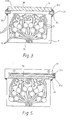
- FIG. 3 One embodiment of an intermediate plate of a head according to the present invention for an ink jet printer is illustrated in Figures 3 and 4.
- the intermediate plate 11 has a plurality of pressure chambers 12, each with a depth of several tens to several hundreds of microns formed on one surface thereof by chemical etching.
- a nozzle 13 is connected to each pressure chamber 12.
- the pressure chambers communicate with the preliminary feed chamber 14 via feed channels 15.
- a further plurality of pressure chambers 16 ( Figure 4) are formed, the pressure chambers 16 being identical to the pressure chambers 12 but offset relative thereto.
- Each pressure chamber 16 communicates with a nozzle 17, the nozzles 17 being offset from the nozzles 13 by one half pitch.
- Ink is supplied to the head by feed pipe 25, the ink being drawn into the pressure chambers 12, 16 by capillary action as ink is ejected from the nozzles 13, 17.
- the intermediate plate 11 is sandwiched between two outer vibration plates 21, 22 to which respective piezo-electric elements 23, 24 are fixed.
- the head shown in Figures 3, 4 and 9 will now be described.
- the head is moved in the direction of an arrow B ( Figure 9) by a mechanism (not illustrated) of a printing apparatus and the piezo-electric elements 23, 24 are energised by control signals from control circuitry (not shown).
- the capacity of the pressure chambers 12, 16 suddenly changes corresponding to the control signals applied to the respective piezo-electric elements and ink is ejected from the nozzles on to a printing medium to form dots of the desired character.
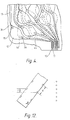
- the distance between the nozzles 13, 17 is indicated by c.
- the distance c is the determining factor in deciding whether timing of printing of the dots should be made with a built-in delay or the head should be made to move by the distance c from the start. If the distance c is less than a distance e between adjacent characters ( Figure 10) the head is not required to print two adjacent characters at the same. time and so the control circuitry of the printing apparatus in which the head is incorporated is relatively simple compared with control circuitry for printing apparatus in which the; conventional heads of Figures 1 and 2 are incorporated.
- the volume and speed of ejection of ink from the nozzles 13, 17 is dependent, inter alia, upon the cross-sectional area of the respective pressure chambers 12, 16 and the length of the feed channels 15.
- the control signals In order to obtain a high quality printing, it is necessary to ensure that the control signals have a constant voltage, constant current and constant phase so that the volume and speed of ejection of ink remains constant. This can be achieved by arranging the length of each of the feed channels 15 connecting the pressure chambers 12, 16 to the preliminary feed chamber 14 to be the same and/or providing a high impedance element 31 where each feed channel 15 communicates with the respective pressure chamber 12, 16.
- the distances between the nozzles 13, 17 and the respective pressure chambers 12, 16 may be made the same for the same purpose but this is difficult to achieve in view of the fact that the nozzles are so closely spaced.
- the pressure chambers 12, 16 are offset, a high density of printing can be realised.
- the length of each of the feed channels 15 is constant to make their impedance the same.
- Figure 8 shows the relationship between driving voltage and volume of ink ejected where the distance between the pressure chambers 12, 16 and the respective nozzles 13, 17 is constant and the length of the feed channel 15 is changed.
- the length of the feed channel 15 in line A is 8 millimetres and in line B is 2 millimetres.
- some air enters the nozzles 13, 17, the amount being dependent, inter alia, upon the surface tension of the ink.
- the ink is subject to different pressures during ejection and during restoration, and the quantity of ink ejected from each nozzle and the time for restoration is made constant for all the nozzles by dimensioning the feed channels 15 suitably to take account of the viscosity of the ink and the impedance of the feed channels.
- Ink is more easily ejected from the nozzles when the pressure chambers 12, 16 are smoothly connected to the nozzles 13, 17 respectively and the impedance is low. Thus it is better to increase the width of the feed channels to equalise the impedance of the feed channels. Further, as the piezo-electric elements 23, 24 are circular, it is desirable to make the pressure chambers 12, 16 substantially circular.
- FIG. 6 Another embodiment of an intermediate plate 11 for a head according to the present invention of an ink jet printer is shown in Figure 6 and has a first island 36 and a second island 35.
- the pressure chamber 12 is substantially circular, high frequency vibration is generated and the pressure within the chamber 12 does not increase uniformly when a control signal is applied to the respective piezo-electric element.
- the first island 36 and the second island 35 prevent the generation of these high frequency vibrations even if the shape of the pressure chambers deviates from circular. It is thus possible to eject the same volume of ink from each of the nozzles.
- an island 37 is disposed within each feed channel in order to increase the impedance thereof and again to prevent high frequency vibrations.
- ink is ejected through the nozzles by applying pressure from the preliminary feed chamber 14, but since the width of the pressure chambers 12, 16 is several times that of the feed channels 15 and the other channels, only air bubbles in the neighbourhood of the centre of the pressure chambers 12 will be ejected through the nozzles 13 and air bubbles adjacent the circumference of the pressure chambers will remain.
- the second islands 35 are provided to ensure that all the air bubbles in the pressure chambers will be ejected through the nozzles.
- the depth D 2 of the nozzle 13 is made less than the depth D 1 of a channel 45 connecting a nozzle to respective pressure chambers.
- efficiency of ejection of ink and response frequency can be improved.
- the depth D 2 of each nozzle is 40-50 ⁇ m
- the length L is 50-300 ⁇ m
- the depth D of the channel 45 is 70-150 ⁇ m in order to achieve the response frequency of about 2 KHz.
- the required length L of the nozzles has a close relationship with the quantity of air entering the nozzle when ink has been ejected and during restoration.
- the amount of air entering through the nozzle is exactly the same as the amount of ink that has just been ejected and it is necessary to prevent boundaries between the air and the ink reaching the channel 45. If this occurs, because some ink still adheres to the opposite side walls of the nozzle, the pressure balance may be changed, even though only slightly, and the ink on one side wall of the nozzle may coalesce with the ink on the opposite side wall and so form an air bubble in the channel 45.
- the thickness of the intermediate plate 11 has been found to be very'important in practice. If the total thickness of the outer vibration plate 21 and the piezo-electric element 23 is equal to the thickness of the intermediate plate 11, which itself is relatively thin since it is made by an etching technique, pressure will increase by only a half. Further, pressure in one pressure chamber will be transmitted to an adjacent pressure chamber on the opposite side of the intermediate plate. As a result, the volume and speed of ejection of ink will vary depending upon whether the adjacent pressure chambers on opposite sides of the intermediate plate are driven at the same time or not. As a result, the quality of printing is reduced. Therefore, it is necessary to prevent adjacent pressure chambers on opposite sides of the intermediate plate influencing each other or to make the influence so small that it may be disregarded.
- the thickness of the intermediate plate should be 0.95 millimetres.
- the thickness of the intermediate plate may be reduced to some extent. If the pressure chambers are etched to a depth of, for example, 70 ⁇ m, the thickness of the intermediate plate is given by:
- chrome and gold layers are deposited on to a plate made of a material which is not affected by ink, for example, borosilicate glass.
- a resist is formed on both sides of the plate and is exposed to light using a photo mask so as to form the pattern, for example, in Figure 3.
- the plate is etched by, for example, hydrofluoric acid to form the channels in the pressure chambers.
- a spacer 38 having almost the same thickness as that of the intermediate plate is disposed at one side of where the preliminary feed chamber 14 is to be formed, and then the intermediate plate so formed is sandwiched between the outer vibration plates 21,22 held by a jig, and put into a furnace at 550° to 700°C.
- An electrically conducted film for example, of NESA (Trade Mark) or In 2 0 3 is formed on the outer vibration plates 21,22 to act as a transparent electrode.
- the conductive film may be formed before or after bonding of the intermediate plate and the vibration plates.
- the intermediate plate and the outer vibration plates are transparent, the channels and pressure chambers are visible but if this is not required, the outer vibration plates and intermediate plates may be made opaque.
- Figure 13a shows the intermediate plate 11 and the spacer 38 of Figure 3 disposed between the two outer vibration plates 21, 22 to form a-space which defines the preliminary feed chamber 14.
- the preliminary feed chamber 14 has an ink inlet 33a and an ink outlet 33b.
- a feed pipe 25 of stainless steel is secured by binder material 34 to each of the ink inlet 33a and the ink outlet 33b.
- Figure 13b shows a head for an ink jet printer incorporating the intermediate plate of Figure 5 showing an ink reservoir 39 made, for example, of plastics material.
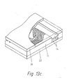
- Figure 13c shows a head for an ink jet printer incorporating the intermediate plate of Figure 6, the preliminary feed chamber 14 being formed by etching on the intermediate plate with the pressure chambers 12.
- the ink outlet 33b for the preliminary feed chamber 14 is not essential but when an air bubble, for example, enters the preliminary feed chamber, if ink is circulated therethrough . the air bubble can be removed without having to push it through the pressure chambers and nozzles etc.
- the shape of the nozzle shown in Figure 11 can be produced by a double etching technique.
- a locating plate 40 ( Figure 7) for determining the position of the piezo-electric elements, is fixed in position by a bonding tag 42 and correctly located by a cross-shaped recess 47 engaging correspondingly shaped projections on the respective outer vibration plates.
- the plate 40 has twelve holes 41 each somewhat larger than the piezo-electric element to be located therein and with a depth of the same as that of the piezo-electric element to be located therein. If the plate 40 is made of metal, it can be used to form electrodes of the piezo-electric elements.
- a piezo-electric element is put into each of the holes 41 and fixed therein by means, of, for example an epoxy resin or a metal solder, such as a gold-tin solder. Then each piezo-electric element is wired to control circuitry of the printing apparatus. In order to improve insulation properties, the wiring is sealed by a soft electrically nonconductive material, such as silicon resin. In order to increase resistance to damage due, for example, to external shock, a coating may be formed on the plate 40.
- the piezo-electric elements may be wired by various methods, such as soldering, electric bonding, wire bonding, or connecting using electric gum, metal etc. Thus a highly integrated head for an ink jet printer can be made. Moreover the surface on which the nozzles debouch may be cut by a diamond cutter or polished to make it smooth.
- the wall between one feed channel and the adjacent feed channel preferably has a width of more than 50 ⁇ m since it is necessary for the wall to have sufficient strength not to be broken if the ink freezes. It has been found that if the wall between adjacent feed channels has a width of 100 ⁇ m, it does not break even when the ink is frozen at -40 C.
- borosilicate glass is preferably used for the intermediate plate and the outer vibration plates due to the ease of etching. However, instead of being etched, the borosilicate glass could be moulded into the desired configuration at high temperature.
- a head according to the present invention of'ink jet printer may be disposed as shown in Figure 12 and inclined at an angle of 8 o to the plane of printing so that a distance f between adjacent dots formed on printing medium is less than the distance d between corresponding adjacent nozzles, i.e.: As a result high density printing will be obtained.
- a head according to the present invention for an ink jet printer may be employed by typewriters, copying presses or facsimile machines etc.
Landscapes
- Engineering & Computer Science (AREA)
- Manufacturing & Machinery (AREA)
- Particle Formation And Scattering Control In Inkjet Printers (AREA)
Applications Claiming Priority (2)
| Application Number | Priority Date | Filing Date | Title |
|---|---|---|---|
| JP35964/80 | 1980-03-21 | ||
| JP3596480A JPH0234781B2 (ja) | 1980-03-21 | 1980-03-21 | Inkujetsutokirokuyohetsudo |
Publications (2)
| Publication Number | Publication Date |
|---|---|
| EP0037624A1 true EP0037624A1 (de) | 1981-10-14 |
| EP0037624B1 EP0037624B1 (de) | 1985-06-19 |
Family
ID=12456636
Family Applications (1)
| Application Number | Title | Priority Date | Filing Date |
|---|---|---|---|
| EP81300577A Expired EP0037624B1 (de) | 1980-03-21 | 1981-02-12 | Kopf für einen Tintenstrahldrucker |
Country Status (3)
| Country | Link |
|---|---|
| EP (1) | EP0037624B1 (de) |
| JP (1) | JPH0234781B2 (de) |
| DE (1) | DE3170973D1 (de) |
Cited By (3)
| Publication number | Priority date | Publication date | Assignee | Title |
|---|---|---|---|---|
| US4611219A (en) * | 1981-12-29 | 1986-09-09 | Canon Kabushiki Kaisha | Liquid-jetting head |
| EP0431692A1 (de) * | 1989-12-08 | 1991-06-12 | Océ-Nederland B.V. | Sandwichartig zusammengefügter Tröpfchengenerator für Farbstrahldrucker |
| WO1992010367A1 (en) * | 1990-12-06 | 1992-06-25 | Markpoint Development Ab | Drop-on-demand liquid ejector arrangement |
Families Citing this family (1)
| Publication number | Priority date | Publication date | Assignee | Title |
|---|---|---|---|---|
| JPS60166462A (ja) * | 1984-02-10 | 1985-08-29 | Fujitsu Ltd | インクジエツトヘツド |
Citations (1)
| Publication number | Priority date | Publication date | Assignee | Title |
|---|---|---|---|---|
| DE2233469B1 (de) * | 1972-07-07 | 1973-08-09 | Olympia Werke Ag, 2940 Wilhelmshaven | Schreibkopf für ein Tintenstrahl-Schreibwerk |
Family Cites Families (5)
| Publication number | Priority date | Publication date | Assignee | Title |
|---|---|---|---|---|
| SE364385B (de) * | 1973-04-25 | 1974-02-18 | Original Odhner Ab | |
| CH581357A5 (de) * | 1974-03-12 | 1976-10-29 | Facit Ab | |
| DE2429232C3 (de) * | 1974-06-18 | 1980-09-11 | Olympia Werke Ag, 2940 Wilhelmshaven | Schreibwerk mit einem Mosaikdruckkopf |
| US4216477A (en) * | 1978-05-10 | 1980-08-05 | Hitachi, Ltd. | Nozzle head of an ink-jet printing apparatus with built-in fluid diodes |
| JPS5586767A (en) * | 1978-12-23 | 1980-06-30 | Seiko Epson Corp | Print head |
-
1980
- 1980-03-21 JP JP3596480A patent/JPH0234781B2/ja not_active Expired - Lifetime
-
1981
- 1981-02-12 EP EP81300577A patent/EP0037624B1/de not_active Expired
- 1981-02-12 DE DE8181300577T patent/DE3170973D1/de not_active Expired
Patent Citations (1)
| Publication number | Priority date | Publication date | Assignee | Title |
|---|---|---|---|---|
| DE2233469B1 (de) * | 1972-07-07 | 1973-08-09 | Olympia Werke Ag, 2940 Wilhelmshaven | Schreibkopf für ein Tintenstrahl-Schreibwerk |
Cited By (4)
| Publication number | Priority date | Publication date | Assignee | Title |
|---|---|---|---|---|
| US4611219A (en) * | 1981-12-29 | 1986-09-09 | Canon Kabushiki Kaisha | Liquid-jetting head |
| US4905017A (en) * | 1981-12-29 | 1990-02-27 | Canon Kabushiki Kaisha | Laminated liquid-jetting head capable of recording in a plurality of colors, a method of producing the head and an apparatus having the head |
| EP0431692A1 (de) * | 1989-12-08 | 1991-06-12 | Océ-Nederland B.V. | Sandwichartig zusammengefügter Tröpfchengenerator für Farbstrahldrucker |
| WO1992010367A1 (en) * | 1990-12-06 | 1992-06-25 | Markpoint Development Ab | Drop-on-demand liquid ejector arrangement |
Also Published As
| Publication number | Publication date |
|---|---|
| JPS56133171A (en) | 1981-10-19 |
| EP0037624B1 (de) | 1985-06-19 |
| DE3170973D1 (en) | 1985-07-25 |
| JPH0234781B2 (ja) | 1990-08-06 |
Similar Documents
| Publication | Publication Date | Title |
|---|---|---|
| EP0430692B1 (de) | Herstellungsverfahren eines Druckkopfes | |
| US4829324A (en) | Large array thermal ink jet printhead | |
| US5992978A (en) | Ink jet recording apparatus, and an ink jet head manufacturing method | |
| US5581861A (en) | Method for making a solid-state ink jet print head | |
| US4367480A (en) | Head device for ink jet printer | |
| US4334234A (en) | Liquid droplet forming apparatus | |
| US5041190A (en) | Method of fabricating channel plates and ink jet printheads containing channel plates | |
| AU647653B2 (en) | Method of manufacturing a high density ink jet printhead array | |
| EP0640481A2 (de) | Tintenstrahldruckkopf | |
| JPS6280054A (ja) | インクジェット式印字ヘッド及びその製造方法 | |
| HK1008845B (en) | Ink jet print head | |
| GB2061829A (en) | Ink jet head | |
| US6942322B2 (en) | Drop-on-demand ink-jet printing head | |
| KR0144654B1 (ko) | 잉크 제트 헤드 | |
| US4387383A (en) | Multiple nozzle ink jet print head | |
| JP4258605B2 (ja) | 液体噴射ヘッド及び液体噴射装置 | |
| EP0037624B1 (de) | Kopf für einen Tintenstrahldrucker | |
| JP3175269B2 (ja) | インクジェット式印字ヘッド | |
| US5410340A (en) | Off center heaters for thermal ink jet printheads | |
| US7168793B2 (en) | Multi-nozzle ink jet head | |
| JPS5839069B2 (ja) | インクジェットヘッドの製造方法 | |
| US7802872B2 (en) | Ink jet printhead and its manufacturing process | |
| JP2959052B2 (ja) | インクジェット式印字ヘッド | |
| JP3564864B2 (ja) | インクジェットヘッドの製造方法 | |
| JP3454258B2 (ja) | インクジェット記録装置 |
Legal Events
| Date | Code | Title | Description |
|---|---|---|---|
| PUAI | Public reference made under article 153(3) epc to a published international application that has entered the european phase |
Free format text: ORIGINAL CODE: 0009012 |
|
| AK | Designated contracting states |
Designated state(s): CH DE FR GB IT LI NL SE |
|
| 17P | Request for examination filed |
Effective date: 19811015 |
|
| RAP1 | Party data changed (applicant data changed or rights of an application transferred) |
Owner name: KABUSHIKI KAISHA SUWA SEIKOSHA Owner name: EPSON CORPORATION |
|
| RAP1 | Party data changed (applicant data changed or rights of an application transferred) |
Owner name: KABUSHIKI KAISHA SUWA SEIKOSHA Owner name: EPSON CORPORATION |
|
| GRAA | (expected) grant |
Free format text: ORIGINAL CODE: 0009210 |
|
| AK | Designated contracting states |
Designated state(s): CH DE FR GB IT LI NL SE |
|
| PG25 | Lapsed in a contracting state [announced via postgrant information from national office to epo] |
Ref country code: SE Effective date: 19850619 Ref country code: NL Effective date: 19850619 Ref country code: LI Effective date: 19850619 Ref country code: IT Free format text: LAPSE BECAUSE OF FAILURE TO SUBMIT A TRANSLATION OF THE DESCRIPTION OR TO PAY THE FEE WITHIN THE PRESCRIBED TIME-LIMIT;WARNING: LAPSES OF ITALIAN PATENTS WITH EFFECTIVE DATE BEFORE 2007 MAY HAVE OCCURRED AT ANY TIME BEFORE 2007. THE CORRECT EFFECTIVE DATE MAY BE DIFFERENT FROM THE ONE RECORDED. Effective date: 19850619 Ref country code: CH Effective date: 19850619 |
|
| REF | Corresponds to: |
Ref document number: 3170973 Country of ref document: DE Date of ref document: 19850725 |
|
| ET | Fr: translation filed | ||
| REG | Reference to a national code |
Ref country code: CH Ref legal event code: PL |
|
| NLV1 | Nl: lapsed or annulled due to failure to fulfill the requirements of art. 29p and 29m of the patents act | ||
| PLBE | No opposition filed within time limit |
Free format text: ORIGINAL CODE: 0009261 |
|
| STAA | Information on the status of an ep patent application or granted ep patent |
Free format text: STATUS: NO OPPOSITION FILED WITHIN TIME LIMIT |
|
| 26N | No opposition filed | ||
| PGFP | Annual fee paid to national office [announced via postgrant information from national office to epo] |
Ref country code: DE Payment date: 19991231 Year of fee payment: 20 |
|
| PGFP | Annual fee paid to national office [announced via postgrant information from national office to epo] |
Ref country code: GB Payment date: 20000209 Year of fee payment: 20 |
|
| PGFP | Annual fee paid to national office [announced via postgrant information from national office to epo] |
Ref country code: FR Payment date: 20000210 Year of fee payment: 20 |
|
| PG25 | Lapsed in a contracting state [announced via postgrant information from national office to epo] |
Ref country code: GB Free format text: LAPSE BECAUSE OF EXPIRATION OF PROTECTION Effective date: 20010211 |
|
| REG | Reference to a national code |
Ref country code: GB Ref legal event code: PE20 Effective date: 20010211 |