EP0039529A2 - Kran - Google Patents
Kran Download PDFInfo
- Publication number
- EP0039529A2 EP0039529A2 EP81200451A EP81200451A EP0039529A2 EP 0039529 A2 EP0039529 A2 EP 0039529A2 EP 81200451 A EP81200451 A EP 81200451A EP 81200451 A EP81200451 A EP 81200451A EP 0039529 A2 EP0039529 A2 EP 0039529A2
- Authority
- EP
- European Patent Office
- Prior art keywords
- boom
- crane
- aforementioned
- parallelogram
- load
- Prior art date
- Legal status (The legal status is an assumption and is not a legal conclusion. Google has not performed a legal analysis and makes no representation as to the accuracy of the status listed.)
- Ceased
Links
Images


Classifications
-
- B—PERFORMING OPERATIONS; TRANSPORTING
- B66—HOISTING; LIFTING; HAULING
- B66C—CRANES; LOAD-ENGAGING ELEMENTS OR DEVICES FOR CRANES, CAPSTANS, WINCHES, OR TACKLES
- B66C23/00—Cranes comprising essentially a beam, boom, or triangular structure acting as a cantilever and mounted for translatory of swinging movements in vertical or horizontal planes or a combination of such movements, e.g. jib-cranes, derricks, tower cranes
- B66C23/06—Cranes comprising essentially a beam, boom, or triangular structure acting as a cantilever and mounted for translatory of swinging movements in vertical or horizontal planes or a combination of such movements, e.g. jib-cranes, derricks, tower cranes with jibs mounted for jibbing or luffing movements
- B66C23/08—Cranes comprising essentially a beam, boom, or triangular structure acting as a cantilever and mounted for translatory of swinging movements in vertical or horizontal planes or a combination of such movements, e.g. jib-cranes, derricks, tower cranes with jibs mounted for jibbing or luffing movements and adapted to move the loads in predetermined paths
- B66C23/10—Cranes comprising essentially a beam, boom, or triangular structure acting as a cantilever and mounted for translatory of swinging movements in vertical or horizontal planes or a combination of such movements, e.g. jib-cranes, derricks, tower cranes with jibs mounted for jibbing or luffing movements and adapted to move the loads in predetermined paths the paths being substantially horizontal; Level-luffing jib-cranes
- B66C23/12—Cranes comprising essentially a beam, boom, or triangular structure acting as a cantilever and mounted for translatory of swinging movements in vertical or horizontal planes or a combination of such movements, e.g. jib-cranes, derricks, tower cranes with jibs mounted for jibbing or luffing movements and adapted to move the loads in predetermined paths the paths being substantially horizontal; Level-luffing jib-cranes with means for automatically varying the effective length of the hoisting rope or cable
-
- B—PERFORMING OPERATIONS; TRANSPORTING
- B66—HOISTING; LIFTING; HAULING
- B66C—CRANES; LOAD-ENGAGING ELEMENTS OR DEVICES FOR CRANES, CAPSTANS, WINCHES, OR TACKLES
- B66C23/00—Cranes comprising essentially a beam, boom, or triangular structure acting as a cantilever and mounted for translatory of swinging movements in vertical or horizontal planes or a combination of such movements, e.g. jib-cranes, derricks, tower cranes
- B66C23/06—Cranes comprising essentially a beam, boom, or triangular structure acting as a cantilever and mounted for translatory of swinging movements in vertical or horizontal planes or a combination of such movements, e.g. jib-cranes, derricks, tower cranes with jibs mounted for jibbing or luffing movements
- B66C23/08—Cranes comprising essentially a beam, boom, or triangular structure acting as a cantilever and mounted for translatory of swinging movements in vertical or horizontal planes or a combination of such movements, e.g. jib-cranes, derricks, tower cranes with jibs mounted for jibbing or luffing movements and adapted to move the loads in predetermined paths
- B66C23/10—Cranes comprising essentially a beam, boom, or triangular structure acting as a cantilever and mounted for translatory of swinging movements in vertical or horizontal planes or a combination of such movements, e.g. jib-cranes, derricks, tower cranes with jibs mounted for jibbing or luffing movements and adapted to move the loads in predetermined paths the paths being substantially horizontal; Level-luffing jib-cranes
- B66C23/14—Cranes comprising essentially a beam, boom, or triangular structure acting as a cantilever and mounted for translatory of swinging movements in vertical or horizontal planes or a combination of such movements, e.g. jib-cranes, derricks, tower cranes with jibs mounted for jibbing or luffing movements and adapted to move the loads in predetermined paths the paths being substantially horizontal; Level-luffing jib-cranes with means, e.g. pantograph arrangements, for varying jib configuration
Definitions
- the invention relates to a crane for handling loads, inter alia of containers which must be moved by said crane over a distance such that means must be provided for moving the load approximately horizontally and reducing the oscillation height of the load with respect to its point of suspension, crane equipped with a jib which is hinged on a gantry and this so that the jib or the compound jib system can pivot from one side of the gantry to the other at beyond the vertical, around a horizontal crane axis.
- the Dutch patent application 266.662 describes in particular a construction which can be applied neither to heavy loads nor to very high trajectories covered by the present application. Indeed, for an identical reach and load capacity, the machine according to the above-mentioned request develops a height of almost 90 m from the ground. The wiring of the machine which appears to have remained at the theoretical stage poses problems whose solution is not outlined in the application in question.
- the object of the invention is to propose a feasible solution of a crane with a tiltable jib from one side of the tower to the other passing through the vertical, a crane which by its exceptional reach can replace container gantry cranes related to machines. known as overhead cranes.
- the newly designed crane is, moreover, universal with regard to the kind of lifting loads that can be handled. If necessary, this type of crane can operate with a four-rope grab (ore transfer) or with the conventional lifting yoke.
- the upper end of the boom is made in a T shape, the lifting cables wound by a lifting winch for the load, which is on one side of the pivot plane of the boom , being brought towards the load, which is on the other side of said pivot plane, on pulleys supported in the T-shaped jib head
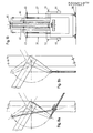
- FIG. 4a is a perspective representation of an auxiliary arrow intended for guiding and stabilizing the load necessary for its drive.
- the lifting cables are stretched in triplicate between the tower head and the boom head.
- This arrangement is in fact conventional in parcel cranes.
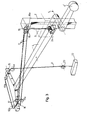
- the crane illustrated in FIGS. 1-5 above, is equipped with a gantry 1 and a crane tower 2. Both the gantry 1 and the tower 2 connected to it can have shapes with very diverse structures.
- Portico 1 is equipped to move on two running rails and it is equipped for this purpose with four feet.
- Each of the four gantry legs has a bogie system which statically uniformly distributes the wheel pressures, by means of running wheels, on running rails not shown.
- the lifting winch with motor, brake, reducer and cable winding drums is mounted in a machine chamber 3.
- the figure, in embodiment Ia, according to FIGS. 1-5, is equipped with an arrow 4.
- the arrow axis 5 is encased on one side and is preferably made in the form of a tube.
- the two arrow support points with respect to the tower 2 are located on the same side of the arrow.
- the arrow support points 6 are formed by two large radial bearings whose outer rings bear in the sides of the tower; the internal rings rotate together with the arrow axis 5.
- the arrow performs during the complete tilting movement, an angle equal to 2a ( Figure 1).
- the boom is completely balanced in each position by a 4bis counterweight.
- the route followed by one of the four lifting cables 1 is, for the embodiment Ia, as follows: (see FIG. 3).
- An essential property of the invention consists in retaining the advantages of this type of wiring, by an arrangement of cable pulleys, during the tilting of the single boom arm.
- the rotation of the tilting boom remains however the most essential quality of the invention, the ho The horizontality (or horizontal load path) is obtained in the embodiment Ia by the aforementioned triple cabling, the cable path of which is described.
- the crane in embodiment Ia, is provided according to the invention with an auxiliary boom ( Figure 4) and a frame guiding the load ( Figure 5) to prevent the rocking effects mentioned above.
- the auxiliary boom 14 is a rigid lattice arm, the lower end of which, for the entire extent of the tilting movement, follows a horizontal path.
- This auxiliary arrow is fixed to articulation on arrow 4 and is driven by a drive drum 20 and a cable transmission 21, in synchronism with the main boom 4.
- the cables 21 are fixed to the periphery of a stationary drum 22, fixed concentrically to the center of rotation of the arrow 4.
- the synchronous movement of the auxiliary boom is obtained because the 2: 1 reduction ratio of the stationary drum 22 to the drive drum 20 doubles the angular displacement of the auxiliary load relative to the angular movement of the boom 4.
- the guide frame (figure 5) or frame guiding the load comprises a horizontal, cantilevered axis of rotation, fixed by two radial bearings in the lower end of the auxiliary boom (figure 4).
- the guide frame comprises four cable pulleys 23, one for each of the four lifting cables.
- the lifting cables 11, starting from the cable pulleys 15, in the T-shaped end of the arrow 4, are guided two by two on the cable pulleys 23.
- FIG. EFLGE It thus forms in the lateral elevation according to FIG. 4a, FIG. EFLGE, with E as projection of the starting line of the cables 11 on the pulleys 15.
- the load 12 is suspended from the four cables 11 which are fixed two by two to the container yoke or parcel yoke which is prevented by doing so by the cables converging at two points, to swing under the influence of horizontal stresses.
- the guide frame suspended at articulation from the auxiliary boom, fitted with cable pulleys, also requires a device which keeps the horizontal plane in which the four cable pulley axes are located, in each position of the boom.
- FIG. 5 a device is provided according to FIG. 5.
- This very simple device which keeps the guide frame horizontal, includes a set of two parallelograms formed by the points Pl, P2, P3, P4 and P3, P4, P5, P6.
- the sections Pl-P3, P2-P4, P3-P6 and P4-P5, are traction cables, P3-P4 is a horizontal lever, articulated, concentric to the auxiliary jib axis, while P5 and P6 are fixed points on the crane tower.
- the embodiment Ia according to the invention therefore comprises a crane, for handling loads, inter alia of containers, with a single boom and an auxiliary boom, a guide frame and a lifting mechanism.
- Embodiment Ib ( Figures 9a, 9b, 9c).
- the embodiment with simple arrow 32 and auxiliary arrow 14 in combination with a compensating arrow 26 comprises a similar embodiment with respect to the embodiment according to Ia.
- the crane according to this embodiment consists of a gantry 1, a tower 2, a jib 32 with T-shaped end and an auxiliary jib 14 with guide frame.
- the embodiment differs from that according to Ia by other means which provide the horizontal load path.
- This embodiment entitled Ib essentially forms the object of FIG. 9a.
- FIG. 9c represents, in a perspective representation, the arrangement of the cables.
- One of the four lifting cables follows a route described as follows.
- the cable runs from the lifting drum 24 to the cable pulley 25 in the rear end of the arm 26 of the compensation arrow and then towards the pulleys 27-28-29-30 in the T-shaped arrow end, and as in the embodiment according to Ia, by means of the guide frame pulleys, towards the load yoke for containers or packages.
- a new element compared to Ia is the compensation arrow.
- This compensation arrow essentially constituted by an articulated arm 26, coupled to the main arrow 32, and a system of bars 31, follows the movement of the main arrow synchronously while the geometry of the figure formed by the deflection points of cables ensures that the sum of the lengths of cables between the drum 24, the pulley 25, the pulleys 27-30 until the load evolves so that the load moves on a horizontal during the tilting or oscillating movement arrow 32.
- the arm 26 of the compensation arrow is arranged such that the movement described by arrow 32 in a vertical oscillation plane is not hampered. Both the arrow 32 and the arm 26 cross the middle position and allow the specific symmetrical load range for the invention.
- the arm 26 is connected by the articulated rods 31 so that the longitudinal axis of the arm always remains parallel to the longitudinal axis of the arrow 32.
- the levers 34 shown in Figures 9a and 9c are provided for this purpose on the arrow 32 and the arm 26 of the compensation arrow.
- the planes described by the pulleys 25 of the compensation arm are located on the opposite side of the tower 2 with respect to the drive rods 31.
- the compensation arm is supported in two radial bearings 33 at the top of the tower.
- the cable pulley system 27-30 is similar to the embodiment Ia with the understanding that the lifting cable extends directly from the lifting drum to the load via the pulleys concerned, the cable path 3 has in the embodiment Ia references between the tower head and the arrow head.
- Embodiment IIa is the preferred embodiment of the invention.
- the assembly of the composite boom forms an articulated parallelogram, each of the above-mentioned boom elements forming a side or part of a side.
- the spout 40 includes a boom body, the lower end of which is equipped with a chassis charge board 45 which follows a correct horizontal path during the flight movement.
- This chassis is articulated relative to the spout 40 about a horizontal axis and moves to the left and to the right, as considered in lateral view with respect to the tower 37, while the support beam 39 is articulated in the middle position by crossing its vertical position.
- the suspension, load 45 chassis is fitted with cable pulleys and suspension points for dead parts.
- the lifting mechanism 46 is arranged in the upper part of the spout 40.
- the four lifting cables extend via the cable pulleys 48 towards the load yoke pulleys and are then hooked to the spring suspension points of the suspension chassis, in which a load limitation 49 is incorporated.
- the control cabin 60 is also suspended from the load suspension chassis 45.
- the upper boom or spout 40 is fixed at an articulation relative to the support beam 39.
- the axis of rotation 50 is horizontal and parallel to the axis of rotation of the suspension frame 45.
- the upper arrow 40 pivots in a vertical plane around the axis of rotation 50, while this articulation in turn pivots around the support beam axis 51.
- the upper arrow 40 and the support beam 39 move in the vertical position side by side while the lifting cables move in parallel vertical planes on the other side of the spout relative to the support beam.
- the load suspension chassis 45 which is provided with cable pulleys 48 and suspension points 49 for the four dead cable parts 47, is prevented from tipping over.
- a device 55 consisting of a drum 56, welded to the chassis 45, a drum forming part of the support beam axis 50, and a set of transmission cables 57.
- the support beam 39 articulated around the axis 51, is a rigid welded beam which forms the support element of the entire boom system with respect to the crane tower and also takes up all the horizontal moments exerted on this boom system.
- the articulation axis 51 is constituted by a tubular axis passing through the tower, mounted without the possibility of twisting between the support beam and the counterweight arm 44.
- the counterweight 44 'establishes the correct balance with the weight of the boom.
- the support beam 39 comprises, approximately at mid-distance along its length, an articulation rod 42 which also forms one side of the articulated parallelogram system and is connected to the hinge of the guide carriage 43.
- the main tie rod 41 which forms a connection between the guide carriage 43 and the spout 40.
- the flight mechanism 52 and 52 ' is produced in duplicate, thanks to the fact that two of the articulation points of the parallelogram are driven. Each mechanism drives two bars.
- the first drive mechanism 52 is installed in the articulation 50 and rotates the spout 40 relative to the support beam 39.
- the second mechanism 52 is installed in the articulation point 54 and rotates the support beam tensioner 42 relative to the support beam 39.
- Each of the drive mechanisms 52 and 52 includes a motor, brake, reducer and pinion pinion with pinion, meshing with a sector of ring gear.
- the drive groups 52 and 52 ′ are located on the support beam 39 and the toothed rings are mounted on the driven bars, respectively the spout 40 and the support beam tensioner 42.
- the motors 52 and 52 ′ are electrically synchronized so that, in the central position (vertical position), deploy the parallelogram in synchronism from this central position in which all the elements are articulated jointly in a plane.
- the entire parallelogram system which represents the compound arrow can therefore pivot beyond the middle position and, considered, in side elevation, move from left to right by relative to tower 37, so that the lifted load can reach the extreme positions, also to the left and to the right (according to Figure 10a) of the crane axis of symmetry.
- This guide carriage 43 is supported with respect to the tower 37, in all directions by guide wheels, so that a uniform regular movement of the articulation point 53 is obtained.
- tower 37 is equipped with six lanes guide (rails) parallel.
- the guide carriage is balanced by a fraction of the counterweight 44 'and is limited in the lowest position by buffers.
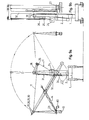
- This crane comprises a gantry crane and a system of jibs composed and mobile.
- This compound system comprises a spout 60, a support beam 61, a main boom 62 with balancing arm and counterweight 63, a short balancing arm 64 and a guide carriage 65.
- the guide carriage 65 moves along a horizontal support beam 65bis formed by a box and equipped with the necessary guide rails.
- the various sides of the parallelogram pivot in vertical planes parallel to each other and this during the entire tilting movement of the boom. This movement takes place from the maximum position to the left to a maximum position to the right (with reference to Figure 14).
- the end of the spout 60 moves on a perfectly horizontal trajectory.
- the path traveled by this end is proportional to the movement of the horizontal displacement carriage 65. This results from the equivalence of the triangles ABC and CDE ( Figure 14).
- the main boom pivots at E in two main bearings.
- the bars 61 and 64 pivot at C and bear on the guide carriage 65.
- This carriage is equipped with four carrying wheels and four guide wheels to which the torque formed by the horizontal components of the forces of the bars 61 and 64 is transmitted.
- the lifting mechanism 66 and the load suspension chassis 67 equipped with a control cabin 68 are integrated into the assembly just as in embodiment IIa.
- the mechanism which ensures the horizontality of the displacement of the load is similar to that which equips embodiment IIa.
- the parallelogram drive devices are mounted respectively in the pivot axes 69 and 70. These devices are units quite simply comprising toothed rings.
- the pivot bearings 69, 71 and 72 are made in the form of radial bearings and bearings of the turning crown as in embodiment IIa.
- the alternative embodiment according to IIb has the advantage that the tower which was found in the embodiment according to IIa disappears and that the guide carriage, which moves horizontally, must not be balanced.
- the spout 60 is shorter than in the previous embodiment and is of lighter construction.
- the counterweight 63 is lighter than in embodiment IIa.
- the disappearance of the crane tower allows a lower construction.
- the portal frame is lighter but less aesthetic because it is made using several box beams.
- FIG. 15 clearly illustrates the manner in which the gantry and the guide beam 65bis are combined.
- the embodiment IVb comprises, as for the embodiments IIIa, IIIb and IVa, an embodiment in double execution in which the tiltable part is practically double while the elements of the arrows are connected horizontally to each other.
- the embodiments described above Ia, Ib and II comprise the crane, according to the invention, capable of describing a continuous movement of the boom system from left to right with respect to the crane tower, considered in side elevation, and in fact in a so-called unilateral realization.
- Variants of analogous embodiments of Ia, Ib and II are obtained by switching to bilateral embodiments, respectively IIIa, IIIb, IV.
- bilateral embodiment it is understood that the articulated elements of the unilateral embodiment are present in duplicate in a crane with a single gantry and a double tower.
- the boom for embodiments IIIa, IIIb and IV is composed of two parallel and similar boom systems, described respectively under Ia, Ib and II.
- T- shaped arrow ends are connected horizontally by a rigid beam 58 ( Figure 1) or 59 ( Figure 12) and assembled in a bridge which is brought to turn by two fly mechanisms.
- the load guide frame remains simple but connects the two auxiliary arrows at their lower ends.
- the cable pulley lifting winches are distributed over the two halves.
- These embodiments IIIa, IIIb and IVa are also universal cranes, that is to say adapted for yoke, single hook, container yoke or grapple operation.
- the chassis with lifting winch 46 forms the second link or upper link between the upper arrows.
- the support beams, tie rods and towers are made symmetrically.
- the counterweights are also presented on each side.
- the flight mechanisms 52 are split: two for each support beam.
- the gantry is to be adapted in width for two towers, each with a guide carriage to be received.
Landscapes
- Engineering & Computer Science (AREA)
- Mechanical Engineering (AREA)
- Jib Cranes (AREA)
Applications Claiming Priority (2)
| Application Number | Priority Date | Filing Date | Title |
|---|---|---|---|
| BE200387 | 1980-04-25 | ||
| BE0/200387A BE882998A (nl) | 1980-04-25 | 1980-04-25 | Kraan |
Publications (2)
| Publication Number | Publication Date |
|---|---|
| EP0039529A2 true EP0039529A2 (de) | 1981-11-11 |
| EP0039529A3 EP0039529A3 (de) | 1981-11-25 |
Family
ID=3843323
Family Applications (1)
| Application Number | Title | Priority Date | Filing Date |
|---|---|---|---|
| EP81200451A Ceased EP0039529A3 (de) | 1980-04-25 | 1981-04-24 | Kran |
Country Status (7)
| Country | Link |
|---|---|
| EP (1) | EP0039529A3 (de) |
| JP (1) | JPS56155191A (de) |
| ES (1) | ES8300632A1 (de) |
| FI (1) | FI811263A7 (de) |
| IT (1) | IT1151494B (de) |
| NL (1) | NL8003262A (de) |
| PT (1) | PT72917B (de) |
Cited By (4)
| Publication number | Priority date | Publication date | Assignee | Title |
|---|---|---|---|---|
| US4606469A (en) * | 1982-08-16 | 1986-08-19 | Frans Swarttour B. V. | Double link level luffing crane |
| EP1099658A1 (de) * | 1999-11-09 | 2001-05-16 | Atecs Mannesmann AG | Lastführung an einem Hafenmobilkran |
| WO2018034566A1 (en) * | 2016-08-15 | 2018-02-22 | Eagle-Access B.V. | System to transfer people and/or cargo during offshore operations |
| US20220250719A1 (en) * | 2019-07-02 | 2022-08-11 | Macartney A/S | A lifting device and methods of operating a lifting device |
Family Cites Families (15)
| Publication number | Priority date | Publication date | Assignee | Title |
|---|---|---|---|---|
| DE651197C (de) * | 1937-10-08 | Luzia Lohmann Geb Thueren | Wippkran | |
| NL6893C (de) * | ||||
| BE413727A (de) * | ||||
| DE595291C (de) * | 1934-04-14 | Heinrich Haferkamp | Wippkran | |
| NL266662A (de) * | ||||
| DE598157C (de) * | 1934-06-06 | Heinrich Haferkamp | Durchschlagender Wippkran | |
| DE520319C (de) * | 1931-03-09 | Maschf Augsburg Nuernberg Ag | Einrichtung zur Erzielung waagerechter Lastbewegung bei Wippkranen mit durchschwingendem Ausleger | |
| DE483160C (de) * | 1929-09-27 | Demag Akt Ges | Durchschlagender Wippkran mit wagerechtem Lastweg | |
| DE678663C (de) * | 1937-02-09 | 1939-07-19 | Luzia Lohmann Geb Thueren | Wippkran |
| NL285563A (de) * | 1961-12-16 | |||
| SE320285B (de) * | 1965-05-19 | 1970-02-02 | C Wadefelt | |
| NO116951B (de) * | 1965-08-18 | 1969-06-09 | Siemens Ag | |
| GB1113740A (en) * | 1966-08-25 | 1968-05-15 | Avery Alfred Simpson Haines | A non-slewing luffing crane |
| SE352056B (de) * | 1969-06-17 | 1972-12-18 | Battelle Memorial Institute | |
| DE1950885A1 (de) * | 1969-10-09 | 1971-04-22 | Demag Ag | Vorrichtung zum Daempfen von Lastpendelbewegungen an Doppellenker-Wippkranen |
-
1980
- 1980-06-04 NL NL8003262A patent/NL8003262A/nl not_active Application Discontinuation
- 1980-08-29 JP JP11855280A patent/JPS56155191A/ja active Pending
- 1980-08-29 IT IT12634/80A patent/IT1151494B/it active
-
1981
- 1981-04-23 FI FI811263A patent/FI811263A7/fi not_active Application Discontinuation
- 1981-04-24 PT PT72917A patent/PT72917B/pt unknown
- 1981-04-24 EP EP81200451A patent/EP0039529A3/de not_active Ceased
- 1981-04-24 ES ES501632A patent/ES8300632A1/es not_active Expired
Cited By (8)
| Publication number | Priority date | Publication date | Assignee | Title |
|---|---|---|---|---|
| US4606469A (en) * | 1982-08-16 | 1986-08-19 | Frans Swarttour B. V. | Double link level luffing crane |
| EP1099658A1 (de) * | 1999-11-09 | 2001-05-16 | Atecs Mannesmann AG | Lastführung an einem Hafenmobilkran |
| WO2018034566A1 (en) * | 2016-08-15 | 2018-02-22 | Eagle-Access B.V. | System to transfer people and/or cargo during offshore operations |
| CN109562813A (zh) * | 2016-08-15 | 2019-04-02 | 鹰通达私人有限公司 | 在海上作业期间传送人员和/或货物的系统 |
| CN109562813B (zh) * | 2016-08-15 | 2020-07-03 | 鹰通达私人有限公司 | 在海上作业期间传送人员和/或货物的系统 |
| US10793232B2 (en) | 2016-08-15 | 2020-10-06 | Eagle-Access B.V. | System to transfer people and/or cargo during offshore operations |
| US20220250719A1 (en) * | 2019-07-02 | 2022-08-11 | Macartney A/S | A lifting device and methods of operating a lifting device |
| US12060137B2 (en) * | 2019-07-02 | 2024-08-13 | Macartney A/S | Lifting device and methods of operating a lifting device |
Also Published As
| Publication number | Publication date |
|---|---|
| ES501632A0 (es) | 1982-11-01 |
| FI811263L (fi) | 1981-10-26 |
| EP0039529A3 (de) | 1981-11-25 |
| PT72917A (fr) | 1981-05-01 |
| PT72917B (fr) | 1982-03-30 |
| NL8003262A (nl) | 1981-11-16 |
| IT8012634A0 (it) | 1980-08-29 |
| ES8300632A1 (es) | 1982-11-01 |
| IT1151494B (it) | 1986-12-17 |
| FI811263A7 (fi) | 1981-10-26 |
| JPS56155191A (en) | 1981-12-01 |
Similar Documents
| Publication | Publication Date | Title |
|---|---|---|
| JP5572125B2 (ja) | 車載式クレーン | |
| EP0635450B1 (de) | Verfahren und Vorrichtung zum Montieren der Ausleger von Turmkränen | |
| CN114031004B (zh) | 一种吊运机 | |
| FR2491046A1 (fr) | Chariot a grue extensible dans les deux sens et grue munie d'un tel chariot | |
| EP1667931B1 (de) | Hebevorrichtung | |
| EP1301431B1 (de) | Kran mit aus gliedern bestehendem kranarm | |
| EP0000295B1 (de) | Hubstapler | |
| EP0277078B1 (de) | Teleskopsäule für Laufkräne | |
| EP0039529A2 (de) | Kran | |
| EP0360702B1 (de) | Zusammenlegbarer Kran mit einem Ausleger, bestehend aus zwei oder drei gelenkig miteinander verbundenen Elementen | |
| EP0408835B1 (de) | Rundfahrgeschäft mit sternförmig angeordneten, schwenkbaren Ausleger- und Pendelarmen | |
| FR2507529A1 (fr) | Transporteur a bande continue, repliable et orientable equipant un vehicule de transport de beton | |
| EP0919509A1 (de) | Vorrichtung zum Handhaben von Containern | |
| FR2643353A1 (fr) | Dispositif pour eviter le balancement d'une charge sous un bati de support, notamment un portique | |
| BE742280A (de) | ||
| CH367957A (fr) | Grue à mât relevable | |
| FR2490166A1 (fr) | Vehicule equipe de dispositifs de transbordement lateral de conteneurs | |
| FR2636616A1 (fr) | Grue repliable a fleche en deux ou trois elements articules les uns aux autres | |
| JP3470801B2 (ja) | 吊具旋回振れ止め装置 | |
| FR2556707A1 (fr) | Engin de levage pour la manutention de containers | |
| FR2655967A1 (fr) | Grue tournante mobile. | |
| EP0911294A1 (de) | Schwingungsdämpfungsvorrichtung für Hubgerät mit kreuzenden Seilen | |
| CH650045A5 (fr) | Machine de chantier ferroviaire pour la saisie et le portage de troncons et/ou d'appareils de voie montes. | |
| EP1121320B1 (de) | Minikran mit gelenken zum handhaben von blöcken | |
| BE882998A (nl) | Kraan |
Legal Events
| Date | Code | Title | Description |
|---|---|---|---|
| PUAI | Public reference made under article 153(3) epc to a published international application that has entered the european phase |
Free format text: ORIGINAL CODE: 0009012 |
|
| PUAL | Search report despatched |
Free format text: ORIGINAL CODE: 0009013 |
|
| AK | Designated contracting states |
Designated state(s): AT BE CH DE FR GB IT NL SE |
|
| AK | Designated contracting states |
Designated state(s): AT BE CH DE FR GB IT NL SE |
|
| 17P | Request for examination filed |
Effective date: 19820323 |
|
| STAA | Information on the status of an ep patent application or granted ep patent |
Free format text: STATUS: THE APPLICATION HAS BEEN REFUSED |
|
| 18R | Application refused |
Effective date: 19870125 |
|
| RIN1 | Information on inventor provided before grant (corrected) |
Inventor name: NELISSEN, PIERRE |