EP0040327A2 - Structure de montage pour moteur de véhicule automobile - Google Patents
Structure de montage pour moteur de véhicule automobile Download PDFInfo
- Publication number
- EP0040327A2 EP0040327A2 EP81102920A EP81102920A EP0040327A2 EP 0040327 A2 EP0040327 A2 EP 0040327A2 EP 81102920 A EP81102920 A EP 81102920A EP 81102920 A EP81102920 A EP 81102920A EP 0040327 A2 EP0040327 A2 EP 0040327A2
- Authority
- EP
- European Patent Office
- Prior art keywords
- engine
- members
- mass
- shock
- coupling member
- Prior art date
- Legal status (The legal status is an assumption and is not a legal conclusion. Google has not performed a legal analysis and makes no representation as to the accuracy of the status listed.)
- Granted
Links
Images


Classifications
-
- F—MECHANICAL ENGINEERING; LIGHTING; HEATING; WEAPONS; BLASTING
- F16—ENGINEERING ELEMENTS AND UNITS; GENERAL MEASURES FOR PRODUCING AND MAINTAINING EFFECTIVE FUNCTIONING OF MACHINES OR INSTALLATIONS; THERMAL INSULATION IN GENERAL
- F16F—SPRINGS; SHOCK-ABSORBERS; MEANS FOR DAMPING VIBRATION
- F16F1/00—Springs
- F16F1/36—Springs made of rubber or other material having high internal friction, e.g. thermoplastic elastomers
- F16F1/42—Springs made of rubber or other material having high internal friction, e.g. thermoplastic elastomers characterised by the mode of stressing
- F16F1/52—Springs made of rubber or other material having high internal friction, e.g. thermoplastic elastomers characterised by the mode of stressing loaded in combined stresses
- F16F1/54—Springs made of rubber or other material having high internal friction, e.g. thermoplastic elastomers characterised by the mode of stressing loaded in combined stresses loaded in compression and shear
-
- F—MECHANICAL ENGINEERING; LIGHTING; HEATING; WEAPONS; BLASTING
- F16—ENGINEERING ELEMENTS AND UNITS; GENERAL MEASURES FOR PRODUCING AND MAINTAINING EFFECTIVE FUNCTIONING OF MACHINES OR INSTALLATIONS; THERMAL INSULATION IN GENERAL
- F16F—SPRINGS; SHOCK-ABSORBERS; MEANS FOR DAMPING VIBRATION
- F16F7/00—Vibration-dampers; Shock-absorbers
- F16F7/10—Vibration-dampers; Shock-absorbers using inertia effect
- F16F7/104—Vibration-dampers; Shock-absorbers using inertia effect the inertia member being resiliently mounted
- F16F7/108—Vibration-dampers; Shock-absorbers using inertia effect the inertia member being resiliently mounted on plastics springs
-
- B—PERFORMING OPERATIONS; TRANSPORTING
- B60—VEHICLES IN GENERAL
- B60G—VEHICLE SUSPENSION ARRANGEMENTS
- B60G2202/00—Indexing codes relating to the type of spring, damper or actuator
- B60G2202/20—Type of damper
- B60G2202/25—Dynamic damper
-
- F—MECHANICAL ENGINEERING; LIGHTING; HEATING; WEAPONS; BLASTING
- F16—ENGINEERING ELEMENTS AND UNITS; GENERAL MEASURES FOR PRODUCING AND MAINTAINING EFFECTIVE FUNCTIONING OF MACHINES OR INSTALLATIONS; THERMAL INSULATION IN GENERAL
- F16F—SPRINGS; SHOCK-ABSORBERS; MEANS FOR DAMPING VIBRATION
- F16F2236/00—Mode of stressing of basic spring or damper elements or devices incorporating such elements
- F16F2236/12—Mode of stressing of basic spring or damper elements or devices incorporating such elements loaded in combined stresses
- F16F2236/123—Mode of stressing of basic spring or damper elements or devices incorporating such elements loaded in combined stresses loaded in compression and shear
Definitions
- the present invention relates to an engine mounting structure used for the mounting of a power plant such as an internal combustion engine on the body structure of an automotive vehicle.
- a conventional engine mounting structure used for the mounting of an internal combustion engine on the body structure of an automotive vehicle comprises a pair of shock and vibration insulating units each using a resilient block.
- the resilient block is connected between the body structure of the vehicle and an engine-side bracket secured to the engine mounted on the vehicle body structure.
- the resilient block forming part of the shock and vibration insulating unit is usually designed to have a relatively large spring constant so as to be capable of taking up the vibrations of the engine under medium-speed cruising conditions of the vehicle.
- the engine tends to produce vibrations at frequencies within a certain relatively low range.
- the vibrations of the engine at such frequencies tend to cause production of stifled, droning noises or "booms" in the vehicle cabin.
- the shock and vibration insulating unit of a conventional engine mounting structure be capable of absorbing such low-frequency vibrations, the resilient block of the shock and vibration insulating unit is required to have an increased weight.
- the present invention contemplates elimination of these and other drawbacks which have thus far been inherent in prior-art engine mounting structures for automotive vehicles.
- an engine mounting structure for mounting an automotive engine on the body structure of an automotive vehicle, comprising at least one shock and vibration insulating unit comprising a first coupling member to be connected to the body structure of the vehicle, a second coupling member to be connected to the body structure of the engine and spaced apart from the first coupling member, a main resilient block structurally interven- ing between the first and second coupling means, and vibration cancelling means comprising at least one combination of a first mass member, a second mass member, a first auxiliary resilient block structurally intervening between the first coupling member and the first mass member, a second auxiliary resilient block structurally intervening between the second coupling member and the second mass member, and a third auxiliary resilient block structurally intervening between the first and second mass members so as to reduce the stifled booming noises to be produced in the vehicle cabin under high-speed cruising conditions of the vehicle.
- Figs. 1 and 2 show a representative example of a known engine mounting structure.
- the engine mounting structure as shown is used for the mounting of an internal combustion engine 1 on a lateral suspension member 2 of the body structure of an automotive vehicle.
- the lateral suspension member 2 extends laterally of the vehicle body structure and is fixedly connected adjacent the opposite lateral ends thereof to right and left side members 3 and 3' of the vehicle body structure.
- the suspension member 2 thus bridging the side members 3 and 3' has a pair of upstanding bracket portions 4 and 4' positioned on body sides of the engine 1 and adjacent to the side members 3 and 3', respectively.
- the prior-art engine mounting structure comprises a pair of shock and vibration insulating units 5 and 5' each of which is connected between each of the bracket portions 4 and 4' of the suspension member 2 and each of engine-side bracket members 6 and 6', respectively, which are secured to the body structure of the engine 1.
- the shock and vibration insulating unit 5 positioned on one side of the engine 1 comprises a resilient block 7 having opposite end faces, a lower coupling member 8 fixedly attached to one of the end faces of the resilient block 7, and an upper coupling member 9 fixedly attached to the other end face of the resilient block 7.
- the shock and vibration insulating unit 5' positioned on the other side of the engine 1 comprises a resilient block 7' having opposite end faces, a lower coupling member 8' fixedly attached to one end face of the resilient block 7', and an upper coupling member 9' fixedly attached to the other end face of the resilient block 7'.
- the lower coupling members 8 and 8' are securely connected to the bracket portions 4 and 4' of the suspension member 2 by means of bolts 10 and 10', respectively, while the upper coupling members 9 and 9' are securely connected to the above mentioned engine-side bracket members 6 and 6' by means of bolts 11 and 11', respectively.
- the resilient blocks ? and 7' are constructed of a material such as rubber having a spring constant which is selected in such a manner that each of the resilient blocks 7 and 7' is capable of absorbing and dampening the shocks and vibrations which are to be produced in the engine 1 under medium-speed cruising conditions of the vehicle.
- each of the resilient blocks 7 and 7' has a relatively large spring constant and is for this reason capable of absorbing and dampening shocks and vibrations at medium cruising speeds of the vehicle but is not suitable for taking up the shocks and vibrations to be produced under high-speed cruising conditions of the vehicle.
- the vibrations produced during high-speed cruising of a vehicle are causative of production of stifled booming noises in the vehicle cabin.
- the resilient blocks 7 and 7' are required to have such weights that are large enough to absorb the vibrations to be produced by the engine under high-speed cruising conditions of the vehicle.
- the provision of such heavy resilient blocks results in unwieldy construction of the engine mounting structure as a whole and requires an additional space and additional time and labor for the installation of the engine and engine mounting structure on the vehicle body.
- Fig. 3 shows part of another representative example of the prior-art engine mounting structure.
- the engine mounting structure comprises a pair of shock and vibration insulating units only one of which is shown and designated by reference numeral 12.
- the shock and vibration insulating unit 12 comprises lower and upper resilient blocks 13 and 14, and a rigid mass member 15 securely interposed between the resilient blocks 13 and 14.
- the lower resilient block 13 is securely attached to a lower coupling member 16 fixedly connected to one of the bracket portions such as the bracket portion 4 of the lateral suspension member 2 of the vehicle body structure.
- the upper resilient block 14 is securely attached to an upper coupling member 17 which is fixed to one of the engine-side bracket members such as the bracket member 6 secured to the body structure of the engine 1.
- the shock and vibration insulating unit 12 thus constructed is usually designed to be capable of absorbing and dampening vibrations with frequencies higher than about 100 Hz.
- the shock and vibration insulating unit included in the prior-art engine mounting structure hereinbefore described with reference to Fig. 3 may be designed in such a manner as to be capable of taking up vibrations with frequencies of about 90 to 140 Hz which are responsible for the production of stifled, droning noises in the vehivle cabin during high-speed cruising of the vehicle.
- the shock and vibration insulating unit 12 it is required to use an extremely large-sized rigid block as the mass member 15.
- Such a large-sized mass member could not be stably mounted on the body structure of an automotive vehicle insofar as the insulating unit has the shown construction.
- the present invention contemplates provision of useful solutions to these drawbacks which'have been inherent in prior- are engine mounting structures of the described natures.
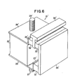
- Fig. 4 to 6 of the drawings show a first preferred embodiment of the engine mounting structure according to the present invention aiming at provision of such solutions.
- the engine mounting structure embodying the present invention is used for the mounting of an automotive internal combustion engine 1 on a suitable lateral support member such as a front suspension member 2 of the body structure of an automotive vehicle.
- the lateral suspension member 2 extends laterally of the vehicle body structure and is fixedly connected adjacent the lateral ends thereof to right and left side members 3 and 3' of the body structure by suitable fastening means such as bolts 18 and 18' and nuts 19 and 19', respectively.
- the lateral suspension member 2 thus bridging the side members 3 and 3' of the vehicle body structure has a pair of upstanding bracket portions 4 and 4' positioned on both sides of the engine 1 and adjacent to the side members 3 and 3', respectively.
- Each of the bracket portions 4 and 4' has an upper end face which is slightly inclined toward the engine 1.
- a pair of rigid engine-side bracket members 6 and 6' which are bolted as at 20 and 20' or otherwise securely connected to the body structure of the engine 1.
- Each of the bracket members 6 and 6' has a lower face spaced apart substantially in parallel from the inclined upper end face of each of the bracket portions 4 and 4' of the lateral suspension member 2.
- the engine mounting structure shown in Fig. 4 further comprises a pair of shock and vibration insulating units 21 and 2 1 ' provided on both sides of the engine 1.
- the shock and vibration insulating unit 21 positioned on one side of the engine comprises a main resilient block 22 of, for example, rubber, having spaced, substantially parallel opposite end faces, a rigid first or lower coupling member 23 securely attached to the one of the end faces of the resilient block 22, and a rigid second or upper rigid coupling member 24 securely attached to the other end face of the resilient block 22.
- the shock and vibration insulating unit 21' provided on the other side of the engine 1 likewise comprises a main resilient block 22' of, for example, rubber having spaced, substantially parallel opposite end faces, a rigid first of lower coupling member 23' securely attached to one of the end faces of the resilient block 22', and a second or upper coupling member 24' securely attached to the other end face of the resilient block 22' as will be better seen from Figs. 5 and 6.
- the lower and upper coupling members 23 and 24 are generally L-shaped in section and have side edge portions 25 and 26, respectively, which are bent from the remaining portions of the coupling members in directions substantially perpendicular to the above mentioned end faces of the resilient block 22.
- the lower and upper coupling members 23' and 24' are generally L-shaped in section and have side edge portions 25' and 26', respectively, which are bent from the remaining portions of the coupling members in directions substantially perpendicular to the opposite end faces of the resilient block 22'.
- Each of the resilient blocks 22 and 22' is constructed of a suitable resilient material having a predetermined spring constant Ke.
- the lower coupling member 23 is fixedly attached to the inclined upper end face of the bracket portion 4 of the suspension member 2 by suitable fastening means such as a bolt 27 welded to the coupling member 23 and secured to the bracket portion 4 by means of a nut 28.
- the lower coupling member 23' is fixedly attached to the inclined upper end face of the bracket portion 4' of the suspension member 2 by suitable fastening means such as a bolt 27' welded to the coupling member 23' and secured to the bracket portion 4' by means of a nut 28'.
- the upper coupling member 24 is fixedly attached to the inclined lower face of the engine-side bracket 6 by suitable fastening means such as a bolt 29 welded to the coupling member 24 and secured to the bracket member 6 by means of a nut 30.
- the upper coupling member 24' is fixedly attached to the inclined lower face of the engine-side bracket member 6' by suitable fastening means such as a bolt 29' welded to the coupling member 24' and secured to the coupling member 24' and secured to the bracket member 6' by means of a nut 30'.
- Each of the shock and vibration insulating units 21 and 21' thus connected between the suspension unit 2 and the engine-side bracket members 6 and 6' further comprises vibration cancelling means adapted to cancel predetermined frequency components of the vibrations to be transmitted through the oscillatory system constituted by each of the hereinbefore described resilient blocks 22 and 22'.
- the vibration cancelling means of the shock and vibration insulating unit 21 is shown comprising first, second and third auxiliary resilient blocks 31, 32 and 33 and first and second mass members 34 and 35, each of the resilient blocks and mass members having substantially parallel opposite end faces.
- the first auxiliary resilient block 31 is securely attached over one of its end faces to the outer face of the bent side edge portion 25 of the lower coupling member 23 and over the other end face thereof to the inner end face of the first mass member 34 and, thus, structurally intervenes between the coupling member 23 and the mass member 34.
- the second auxiliary resilient block 32 is securely attached over one of its end faces to the outer face of the bent side edge portion 26 of the upper coupling member 24 and over the other end face thereof to the inner end face of the second mass member 35 and, thus, structurally intervenes between the coupling member 24 and the mass member 35.
- the third auxiliary resilient block 33 is securely attached over one of its end faces to the outer end face of the second mass member 35 and over the other end face thereof to the inner end face of the first mass member 34 and, thus, structurally intervenes between the first and second mass members 34 and 35.
- the first, second and third auxiliary resilient blocks 31, 32 and 33 are constructed of suitable resilient materials having predetermined spring constants which are herein assumed to be K 1 , K2 and K3 , respectively, while the first and second mass members 34 and 35 are designed to have predetermined masses which are herein assumed to be M 1 and M 2 , respectively.
- the vibration cancelling means of the other shock and vibration insulating unit 21' is similar in construction to the above described vibration cancelling means of the insulating unit 21 and thus comprises first, second and third auxiliary resilient blocks 31', 32' and 33' and first and second mass members 34' and 35', each of these resilient blocks and mass members also having substantially parallel opposite end faces.
- the first auxiliary resilient block 31' is securely attached over one of its end faces to the outer face of the bent side edge portion 25' of the lower coupling member 23 and over the other end face thereof to the inner end face of the first mass member 34' and, thus, structurally intervenes between the coupling member 23'and the mass member 34'.
- the second auxiliary resilient block 32' is securely attached over one of its end faces to the outer face of the bent side edge portion 26' of the upper coupling member 24'and over the other end face thereof to the inner end face of the second mass member 35' and, thus, structurally intervenes between the coupling member 24'and the mass member 35'.
- the third auxiliary resilient block 33' is securely attached over one of its end faces to the outer end face of the second mass member 35' and over the other end face thereof to the inner end face of the first mass member 34' and, thus, structurally inte-rvenes between the first and second mass members 34' and 35'.
- the first, second and third auxiliary resilient blocks 31', 32' and 33' are constructed of suitable resilient materials having predetermined spring constants while the first and second mass members 34' and 35' are designed to have predetermined masses.
- Each of the first mass members 34 and 34' is assumed to in the form of a flat plate and each of the second mass members 35 and 35' is assumed to have a generally T-shaped cross section, as will be seen from Figs. 5 and 6.
- each of the shock and vibration insulating units 21 and 21' thus constructed and arranged constitutes an oscillatory system 36 which is schematical ly illustrated in Fig. 7 of the drawings.
- the spring constant Fs/x thus determined of the oscillatory system 36 is graphically represented in terms of the vibration frequency f by curve a shown in Fig. 8. From curve a it will be understood that the spring constant Fs/x of the oscillatory system 36 assumes maximal values at certain two frequencies f 1 and f 2 . On the other hand, the force Fs transmitted from the oscillatory system 36 to the suspension member 2 is in phase with the displacement x at vibration frequencies lower than the frequency f 1 and at vibration frequencies higher than the frequency f 2 and is 180 degrees out of phase with the displacement x at vibration frequencies between the two frequencies f 1 and f2, as will be seen from curve b shown in Fig. 9.
- each of the main resilient blocks 22 and 22' of the shock and vibration insulating units 21 and 21' forms part of an oscillatory system 37 schematically shown in Fig. 10.
- the oscillatory system 37 thus constituted by each of the resilient blocks 22 and 22' is subjected to vibrations with the displacement x and the exciting frequency f
- the force Fe transmitted from the oscillatory system 37 to the suspension member 2 is given by when the vibration components damped by the resilient block forming part of the oscillatory system 37 are excluded from the force.
- the spring constant Fe/x of the oscillatory system 37 remains substantially constant throughout the range of the vibration frequency f as will be seen from plot c shown in Fig. 12.
- Fig. 11 shows schematically an oscillatory system 38 composed of the parallel combination of the above described oscillatory systems 36 and 37.
- the oscillatory system 38 shown in Fig. 11 is thus constituted by each of the shock and vibration insulating units 21 and 21' of the engine mounting structure shown in Figs. 4 to 6.
- Fig. 12 is further shown a curve d which represents the relationship between the frequency f and the spring constant Ft/x achieved of the oscillatory system 38 composed of the parallel combination of the oscillatory systems 36 and 37.
- each of the shock and vibration insulating units 21 and 21' is given by the sum of the forces Fs and Fe at vibration frequencies lower than the frequency f 1 and at vibration frequencies higher than the frequency f 2 and by the difference between the forces Fs and Fe at vibration frequencies higher than the frequency f 1 and lower than the frequency f 2 .
- the oscillatory system 38 composed of the parallel combination of the main and auxiliary oscillatory systems 36 and 37 exhibits performance characteristics such that the spring constant Ft/x of the system 38 as a whole is smaller than the spring constant Fe/x of the main oscillatory system 37 at vibration frequencies within the range of between the frequencies f 1 and f 2 as will be clearly seen from the curves c and d of Fig. 12.
- the frequencies f 1 and f 2 stand for the resonance frequencies of the suspension member 2.
- each of the respective spring constants K 1 and K 2 of the first and second auxiliary resilient blocks 31 and 32 is assumed, for the sake of simplicity, to has a value k and each of the respective masses M 1 and M 2 of the first and second mass members 34 and 35 is assumed to have a value m, then the force Fs and the resonance frequencies f 1 and f 2 are given by the following equations: and
- each of the shock and vibration insulating units 21 and 21' is effective to reduce such noises to a minimum if the insulating unit is designed in such a manner that the above mentioned resonance frequencies f1 and f2 equal about 90H z and about 220Hz, respectively.
- Such a purpose can be achieved when the main resilient block 22 and the first, second and third auxiliary resilient blocks 31, 32 and 33 are designed so that the spring constant Ke falls within the range of between about 25 Kgs/mm and about 45 kgs/mm, the spring constants K 1 and K 2 fall within the range of between about 5 kgs/mm and about 20 kgs/mm and the spring constant K 3 falls within the range of between about 10 kgs/mm and about 35 kgs/mm if each of the respective masses M 1 and M 2 of the mass members 34 and 35 is selected to fall within the range of between about 0.3 kg and about 1.0 kg.
- each of the shock and vibration insulating units 21 and 21' in the above described manner is conducive not only to reduction of booming noises to be produced in a vehicle cabin under high-speed cruising conditions of the vehicle but to isolation of the vehicle body from the vibrations of the engine producing vibrations at frequencies in the neighborhood of 10Hz.
- the shock and vibration insulating units 2 1 and 21' are secured to the bracket portions 4 and 4', respectively, of the suspension member 2 by the bolts 2? and 27' and nuts 28 and 28'.
- the engine 1 having the engine-side bracket members 6 and 6' preliminarily attached thereto by the bolts is thereafter assembled to the shock and vibration insulating units 21 and 21' by tightening the bolts 29 and 29' to the engine-side bracket members 6 and 6' by means of the nuts 30 and 30', respectively.
- Figs. 13 and 14 of the drawings show a shock and vibration insulating unit 39 which forms part of a second embodiment of the engine mounting structure according to the present invention.
- the shock and vibration insulating unit 39 is a modification of the insulating unit 21' shown in Figs. 5 and 6 and constitutes one of two such units of an engine mounting structure embodying the present invention.
- the shock and vibration insulating unit 39 comprises a main resilient block 22' of, for example, rubber having substantially parallel opposite end faces, a rigid first or lower coupling member 23' securely attached to one of the end faces of the resilient block 22; and a rigid second or upper coupling member 24' securely attached to the other end face of the resilient block 22'.
- the lower coupling member 23' is generally U-shaped in section and has a pair of side edge portions 25a and 23b which are spaced apart substantially in parallel from each other and which are bent from the remaining portion of the coupling member 23' in directions substantially perpendicular to the above mentioned end faces of the resilient block 22'.
- the upper coupling member 24' is generally U-shaped in section and has a pair of side edge portions 26a and 26b which are spaced apart substantially in parallel from each other and which are bent from the remaining portion of the coupling member 24' in directions substantially perpendicular to the end faces of the resilient block 22'.
- the side edge portions 26a and 26b of the upper coupling member 24' are spaced apart from and substantially aligned with the side edge portions 25a and 25b, respectively, of the lower coupling member 23' in directions parallel with the direction of thickness of the resilient block 22'.
- the resilient block 22' is constructed of a suitable resilient material having a predetermined spring constant.
- the shock and vibration insulating unit 39 shown in Figs. 13 and 14 of drawings further comprises a pair of vibration cancelling means which are provided symmetrically across the main resilient block 22'.
- Each of these two vibration cancelling means is similar in construction to the vibration cancelling means-of each of the shock and vibration insulating units 21 and 21' in the embodiment of Fig. 4.
- the vibration cancelling means of the shock and vibration insulating unit 39 shown in Figs. 13 and 14 comprises a pair of first auxiliary resilient blocks 31a and 31b, a pair of second auxiliary resilient blocks 32a and 32b, a pair of third auxiliary resilient blocks 33a and 33b, a pair of first mass members 34a and 34b, and a pair of second mass members 35a and 35b.
- Each of these resilient blocks and mass members has opposite end faces which are substantially parallel with each other.
- the first auxiliary resilient blocks 31a and 31b are fixedly attached each over one of its end faces to the outer faces of the bent side edge portions 25a and 25b, respectively, of the lower coupling member 23'and over the other end faces thereof to the inner faces of the first mass members 34a and 34b, respectively.
- the second auxiliary resilient blocks 32a and 32b are fixedly attached each over one of its end faces to the outer faces of the bent side edge portions 26a and 26b, respectively, of the upper coupling member 24'and over the other end faces thereof to the inner faces of the second mass members 35a and 35b, respectively.
- each of the first auxiliary resilient blocks 31a and.31b structurally intervenes between the lower coupling member 23' and each of the first mass members 34a and 34b and, likewise, each of the second auxiliary resilient blocks 32a and 32b structurally intervenes between the upper coupling member 24 1 and each of the second mass members 35a and 35b.
- the third auxiliary resilient blocks 33a and 33b are fixedly attached each over one of its end faces to the outer faces of the second mass members 35a and 35b, respectively, and over the other end faces thereof to the inner faces of the first mass members 34a and 34b, respectively.
- Each of the third auxiliary resilient blocks 33a and 33b thus structurally intervenes between each of the first mass members 34a and 34b and each of the second mass members 35a and 35b.
- Each of the auxiliary resilient blocks 31a, 31b, 32a, 32b, 33a and 33b is constructed of a suitable resilient material having a predetermined spring constant and each of the mass members 34a, 34b, 35a and 35b is designed to have a predetermined mass.
- the shock and vibration insulating unit 39 thus constructed is securely connected to the bracket portions of a suitable cross member such as a front suspension member of a vehicle body structure by means of, for example, a bolt 27' projecting from the lower coupling member 23'and further to the body structure of an automotive engine by means of, for example, a bolt 29 ! projecting from the upper coupling member 24'and screwed to one of suitable engine-side bracket members secured to the body structure of the engine.
- a suitable cross member such as a front suspension member of a vehicle body structure by means of, for example, a bolt 27' projecting from the lower coupling member 23'and further to the body structure of an automotive engine by means of, for example, a bolt 29 ! projecting from the upper coupling member 24'and screwed to one of suitable engine-side bracket members secured to the body structure of the engine.
- each of the two vibration cancelling means forming part of the shock and vibration insulating unit 39 shown in Figs. 13 and 14 constitutes an oscillatory system similar to the oscillatory system 36 illustrated in Fig. 7.
- the engine mounting structure using the shock and vibration insulating unit 39 is adapted to provide a wide range of selection among various performance characteristics which can be varied by varying the respective performance characteristics of the oscillatory systems constituted by the two vibration cancelling means of the unit 39.
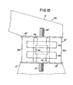
- Figs. 15 and 16 of the drawings show a shock and vibration insulating unit 40 which forms part of third preferred embodiment of the engine mounting structure according to the present invention.
- the shock and vibration insulating unit 40 is also a modification of the insulating unit 21' shown in Figs. 5 and 6 and constitutes one of the two such shock and vibration insulating units of an engine mounting structure embodying the present invention.
- the shock and vibration insulating unit 40 comprises a main resilient block 22' consisting of two independent sections 22a and 22b which are spaced apart substantially in parallel from each other and each of which has substantially parallel opposite end faces.
- the shock and vibration insulating unit 40 further comprises a rigid first or lower coupling member 23'securely attached to one of the end faces of each of the sections 22a and 22b, and a rigid second or upper coupling member 24'securely attached to the other end faces of the sections 22a and 22b.
- the resilient block 22' thus composed of the two sections 22a and 22b is constructed of a suitable resilient material such as rubber having a predetermined spring constant.
- the shock and vibration insulating unit 40 shown in Figs. 15 and 16 further comprises vibration cancelling means comprising first and second or lower and upper auxiliary resilient blocks 41 and 42 positioned intermediate between the sections 22a and 22b of the main resilient block 22' and each having substantially parallel opposite end faces.
- the lower auxiliary resilient block 41 is securely attached over one of its opposite end faces to the inner face of the lower coupling member 23'and, likewise, the upper auxiliary resilient block 42 is securely attached over one of its end faces to the inner face of the upper coupling member 24:
- the lower and upper auxiliary resilient blocks 41 and 42 are sidewise spaced apart from the sections 22a and 22b of the main resilient block 22' and has the other end faces thereof spaced apart substantially from each other as will be seen from the illustration by broken lines in Fig. 15.
- the vibration cancelling means of the shock and vibration insulating unit 40 shown in Figs. 15 and 16 further comprises a pair of first mass members 43 and 43' and a pair of second mass members 44 and 44'.
- the first and second mass members 43 and 44 are positioned on one side of the main resilient block 22' and the first and second mass members 43' and 44' are positioned on the other side of the resilient block 22'as will be seen from Fig. 16.
- each of the mass members 43, 43', 44 and 44' has a lug portion 45 projecting into the spacing between the sections 22a and 22b of the main resilient block 22'.
- Each of the four mass members is designed to have a predetermined mass.
- the vibration cancelling means of the insulating unit 40 illustrated in Figs. 15 and 16 further comprises a third auxiliary resilient block 46 which has substantially parallel opposite end faces and which is fixedly attached over one of its end faces to the respective lug portions 45 of the first mass members 43 and 43' and over the other end face thereof to the respective lug portions 45 of the second mass members 44 and 44'.
- the third auxiliary resilient block 46 structurally intervenes between each of the first mass member 43 and 43' and each of the second mass members 44 and 44'.
- Each of the auxiliary resilient blocks 41, 42 and 46 of the shock and vibration insulating unit 40 is also constructed of a suitable resilient material such as compressible rubber having a predetermined spring constant.
- a compressible rubber as the material of the resilient blocks 41, 42 and 46 will add to the durability and accordingly the service life of the shock and vibration insulating unit 40 as a whole.
- the shock and vibration insulating unit 40 thus constructed is securely connected between one of the bracket portions of a suitable cross member such as a front suspension member of a vehicle body structure by means of, for example, a bolt 27 f projecting-from the lower coupling member 23'and further to the body structure of an automotive engine by means of, for example, a bolt 29'projecting from the upper coupling member 24' and screwed into one of engine-side bracket members secured to the engine body structure.
- a suitable cross member such as a front suspension member of a vehicle body structure by means of, for example, a bolt 27 f projecting-from the lower coupling member 23'and further to the body structure of an automotive engine by means of, for example, a bolt 29'projecting from the upper coupling member 24' and screwed into one of engine-side bracket members secured to the engine body structure.
- the engine mounting structure according to the present invention is characterized by the provision of the vibration cancelling means in each of the shock and vibration insulating units of the structure.
- vibration cancelling means By virtue of such vibration cancelling means, not only transmission of vibrations from the engine to the vehicle body structure during medium-speed cruising of the vehicle but also production of stifled booming noises in the vehicle cabin under high-speed cruising conditions of the vehicle can be precluded effectively.
Landscapes
- Engineering & Computer Science (AREA)
- General Engineering & Computer Science (AREA)
- Mechanical Engineering (AREA)
- Health & Medical Sciences (AREA)
- Child & Adolescent Psychology (AREA)
- Vibration Prevention Devices (AREA)
- Arrangement Or Mounting Of Propulsion Units For Vehicles (AREA)
Applications Claiming Priority (2)
| Application Number | Priority Date | Filing Date | Title |
|---|---|---|---|
| JP51350/80 | 1980-04-17 | ||
| JP55051350A JPS6015808B2 (ja) | 1980-04-17 | 1980-04-17 | エンジンのマウンテイング装置 |
Publications (3)
| Publication Number | Publication Date |
|---|---|
| EP0040327A2 true EP0040327A2 (fr) | 1981-11-25 |
| EP0040327A3 EP0040327A3 (en) | 1982-05-26 |
| EP0040327B1 EP0040327B1 (fr) | 1984-10-03 |
Family
ID=12884471
Family Applications (1)
| Application Number | Title | Priority Date | Filing Date |
|---|---|---|---|
| EP81102920A Expired EP0040327B1 (fr) | 1980-04-17 | 1981-04-15 | Structure de montage pour moteur de véhicule automobile |
Country Status (5)
| Country | Link |
|---|---|
| US (1) | US4440375A (fr) |
| EP (1) | EP0040327B1 (fr) |
| JP (1) | JPS6015808B2 (fr) |
| AU (1) | AU526095B2 (fr) |
| DE (1) | DE3166415D1 (fr) |
Cited By (8)
| Publication number | Priority date | Publication date | Assignee | Title |
|---|---|---|---|---|
| US4403762A (en) * | 1981-02-20 | 1983-09-13 | General Motors Corporation | Low force transmissibility mount |
| EP0189510A1 (fr) * | 1985-01-15 | 1986-08-06 | Firma Carl Freudenberg | Support de moteur |
| EP0131795A3 (en) * | 1983-07-06 | 1987-02-04 | Nissan Motor Co., Ltd. | Improved insulator for use in automotive suspension or the like |
| EP0410941A1 (fr) * | 1989-07-26 | 1991-01-30 | FIAT AUTO S.p.A. | Support élastique avec déphaseur incorporé, en particulier pour moteurs de véhicules |
| EP0428949A1 (fr) * | 1989-11-20 | 1991-05-29 | Psa Sistemi Antivibranti S.P.A. | Support pour moteur |
| EP0627572A1 (fr) * | 1993-05-17 | 1994-12-07 | Metzeler Gimetall Ag | Arrangement pour minimiser la raideur dynamique d'un support élastomérique pour certaines fréquences |
| US5570757A (en) * | 1993-11-22 | 1996-11-05 | Textron Inc. | Engine mounting system for a car |
| GB2339263A (en) * | 1998-07-08 | 2000-01-19 | Draftex Ind Ltd | Restraining link |
Families Citing this family (8)
| Publication number | Priority date | Publication date | Assignee | Title |
|---|---|---|---|---|
| DE3402401A1 (de) * | 1984-01-25 | 1985-07-25 | Adam Opel AG, 6090 Rüsselsheim | Lageranordnung, insbesondere motorlager fuer kraftfahrzeuge |
| US4610420A (en) * | 1984-02-16 | 1986-09-09 | Nissan Motor Company, Limited | Apparatus for mounting power unit |
| DE3431324A1 (de) * | 1984-08-25 | 1986-03-06 | Adam Opel AG, 6090 Rüsselsheim | Anordnung zur lagerung eines motors am fahrwerk eines kraftfahrzeuges |
| JPS63182338U (fr) * | 1987-05-15 | 1988-11-24 | ||
| US5523530A (en) * | 1994-07-25 | 1996-06-04 | United Technologies Corporation | Elastomeric acoustic insulator |
| US5687948A (en) * | 1995-09-26 | 1997-11-18 | Lord Corporation | Vibration isolation system including a passive tuned vibration absorber |
| US11486460B2 (en) * | 2019-08-27 | 2022-11-01 | Deere & Company | Work vehicle with tuned mass dampers |
| DE102024002786A1 (de) * | 2024-08-29 | 2026-03-05 | Man Truck & Bus Se | Dämpfungsvorrichtung zur Dämpfung von Schwingungen an einem Fahrzeug sowie Fahrzeug |
Family Cites Families (5)
| Publication number | Priority date | Publication date | Assignee | Title |
|---|---|---|---|---|
| FR1135312A (fr) * | 1955-06-21 | 1957-04-26 | Anciens Etablissements Panhard | Procédé pour améliorer l'isolement anti-vibratoire conféré par un dispositif isolant, absorbant ou élastique, quelconque |
| US3388772A (en) * | 1966-06-16 | 1968-06-18 | Continental Motors Corp | Vibration absorber |
| FR2431639A1 (fr) * | 1978-07-19 | 1980-02-15 | Ouest Cie | Support elastique antivibratoire a dephaseur incorpore |
| FR2444852A1 (fr) * | 1978-12-19 | 1980-07-18 | Peugeot | Cale elastique de suspension, a filtrage de vibrations de frequence elevee |
| JPS56108307A (en) * | 1980-02-01 | 1981-08-27 | Nissan Motor Co Ltd | Device for supporting engine |
-
1980
- 1980-04-17 JP JP55051350A patent/JPS6015808B2/ja not_active Expired
-
1981
- 1981-04-07 US US06/251,855 patent/US4440375A/en not_active Expired - Lifetime
- 1981-04-13 AU AU69448/81A patent/AU526095B2/en not_active Ceased
- 1981-04-15 DE DE8181102920T patent/DE3166415D1/de not_active Expired
- 1981-04-15 EP EP81102920A patent/EP0040327B1/fr not_active Expired
Cited By (11)
| Publication number | Priority date | Publication date | Assignee | Title |
|---|---|---|---|---|
| US4403762A (en) * | 1981-02-20 | 1983-09-13 | General Motors Corporation | Low force transmissibility mount |
| EP0131795A3 (en) * | 1983-07-06 | 1987-02-04 | Nissan Motor Co., Ltd. | Improved insulator for use in automotive suspension or the like |
| US4889328A (en) * | 1983-07-06 | 1989-12-26 | Nissan Motor Company, Limited | Insulator for use in automotive suspension or the like |
| EP0189510A1 (fr) * | 1985-01-15 | 1986-08-06 | Firma Carl Freudenberg | Support de moteur |
| EP0410941A1 (fr) * | 1989-07-26 | 1991-01-30 | FIAT AUTO S.p.A. | Support élastique avec déphaseur incorporé, en particulier pour moteurs de véhicules |
| EP0428949A1 (fr) * | 1989-11-20 | 1991-05-29 | Psa Sistemi Antivibranti S.P.A. | Support pour moteur |
| US5156380A (en) * | 1989-11-20 | 1992-10-20 | Pirelli Sistemi Antivibranti S.P.A. | Damping support for mounting an engine to a frame |
| EP0627572A1 (fr) * | 1993-05-17 | 1994-12-07 | Metzeler Gimetall Ag | Arrangement pour minimiser la raideur dynamique d'un support élastomérique pour certaines fréquences |
| US5570757A (en) * | 1993-11-22 | 1996-11-05 | Textron Inc. | Engine mounting system for a car |
| GB2339263A (en) * | 1998-07-08 | 2000-01-19 | Draftex Ind Ltd | Restraining link |
| GB2339263B (en) * | 1998-07-08 | 2002-07-17 | Draftex Ind Ltd | Restraining link |
Also Published As
| Publication number | Publication date |
|---|---|
| EP0040327B1 (fr) | 1984-10-03 |
| DE3166415D1 (en) | 1984-11-08 |
| EP0040327A3 (en) | 1982-05-26 |
| AU526095B2 (en) | 1982-12-16 |
| US4440375A (en) | 1984-04-03 |
| JPS56149215A (en) | 1981-11-19 |
| JPS6015808B2 (ja) | 1985-04-22 |
| AU6944881A (en) | 1981-10-22 |
Similar Documents
| Publication | Publication Date | Title |
|---|---|---|
| US4456213A (en) | Engine mounting structure | |
| EP0040327A2 (fr) | Structure de montage pour moteur de véhicule automobile | |
| US4951930A (en) | Insulator for use in automotive suspension or the like | |
| US4445662A (en) | Engine mounting structure | |
| US4381043A (en) | Engine mounting structure | |
| US4420060A (en) | Engine mount arrangement | |
| EP0052291B1 (fr) | Système d'absorption de vibrations pour véhicule automobile | |
| US4610420A (en) | Apparatus for mounting power unit | |
| CA1219017A (fr) | Systeme de stabilisation et d'isolation d'une cabine de vehicule | |
| US4203499A (en) | Apparatus for preventing or damping vibrations and noise in a vehicle | |
| CA1226307A (fr) | Amortisseur de vibrations | |
| JPS6134180Y2 (fr) | ||
| US6070849A (en) | Resilient suspension device for an exhaust pipe | |
| US4634088A (en) | Suspension element for the exhaust system of a motor vehicle engine | |
| EP0077052A2 (fr) | Montage de l'unité motrice de véhicule moteur | |
| CA1240346A (fr) | Support amortisseur a fluide visqueux et organes actifs concus pour agir en fonction de l'intensite de chocs ou de vibrations | |
| EP3798029B1 (fr) | Agencement de suspension pour un véhicule de travail | |
| EP1410937B1 (fr) | Structure de support d'une unite de dispositif de disque | |
| JPH0324539B2 (fr) | ||
| US4385774A (en) | Heavy duty vehicle suspension system | |
| JPS6354568B2 (fr) | ||
| JPH029190B2 (fr) | ||
| JPS6234040Y2 (fr) | ||
| EP0214825A2 (fr) | Amortisseur de vibration | |
| EP0521987B1 (fr) | Moyen d'attenuation de vibrations |
Legal Events
| Date | Code | Title | Description |
|---|---|---|---|
| PUAI | Public reference made under article 153(3) epc to a published international application that has entered the european phase |
Free format text: ORIGINAL CODE: 0009012 |
|
| AK | Designated contracting states |
Designated state(s): DE FR GB |
|
| PUAL | Search report despatched |
Free format text: ORIGINAL CODE: 0009013 |
|
| AK | Designated contracting states |
Designated state(s): DE FR GB |
|
| 17P | Request for examination filed |
Effective date: 19820419 |
|
| GRAA | (expected) grant |
Free format text: ORIGINAL CODE: 0009210 |
|
| AK | Designated contracting states |
Designated state(s): DE FR GB |
|
| REF | Corresponds to: |
Ref document number: 3166415 Country of ref document: DE Date of ref document: 19841108 |
|
| ET | Fr: translation filed | ||
| RAP2 | Party data changed (patent owner data changed or rights of a patent transferred) |
Owner name: NISSAN MOTOR CO., LTD. |
|
| PLBE | No opposition filed within time limit |
Free format text: ORIGINAL CODE: 0009261 |
|
| 26N | No opposition filed | ||
| PG25 | Lapsed in a contracting state [announced via postgrant information from national office to epo] |
Ref country code: FR Free format text: LAPSE BECAUSE OF NON-PAYMENT OF DUE FEES Effective date: 19871230 |
|
| GBPC | Gb: european patent ceased through non-payment of renewal fee | ||
| REG | Reference to a national code |
Ref country code: FR Ref legal event code: ST |
|
| PG25 | Lapsed in a contracting state [announced via postgrant information from national office to epo] |
Ref country code: GB Effective date: 19881118 |
|
| PGFP | Annual fee paid to national office [announced via postgrant information from national office to epo] |
Ref country code: DE Payment date: 19970418 Year of fee payment: 17 |
|
| PG25 | Lapsed in a contracting state [announced via postgrant information from national office to epo] |
Ref country code: DE Free format text: LAPSE BECAUSE OF NON-PAYMENT OF DUE FEES Effective date: 19990202 |