EP0040437B1 - Herstellungsverfahren für ein magnetisches Aufzeichnungsmedium - Google Patents
Herstellungsverfahren für ein magnetisches Aufzeichnungsmedium Download PDFInfo
- Publication number
- EP0040437B1 EP0040437B1 EP81103899A EP81103899A EP0040437B1 EP 0040437 B1 EP0040437 B1 EP 0040437B1 EP 81103899 A EP81103899 A EP 81103899A EP 81103899 A EP81103899 A EP 81103899A EP 0040437 B1 EP0040437 B1 EP 0040437B1
- Authority
- EP
- European Patent Office
- Prior art keywords
- belt
- support
- endless
- metal
- rollers
- Prior art date
- Legal status (The legal status is an assumption and is not a legal conclusion. Google has not performed a legal analysis and makes no representation as to the accuracy of the status listed.)
- Expired
Links
- 230000005291 magnetic effect Effects 0.000 title claims description 29
- 238000004519 manufacturing process Methods 0.000 title claims description 13
- 229910052751 metal Inorganic materials 0.000 claims description 48
- 239000002184 metal Substances 0.000 claims description 48
- 238000000034 method Methods 0.000 claims description 42
- XEEYBQQBJWHFJM-UHFFFAOYSA-N Iron Chemical compound [Fe] XEEYBQQBJWHFJM-UHFFFAOYSA-N 0.000 claims description 26
- 238000001704 evaporation Methods 0.000 claims description 21
- 229910052742 iron Inorganic materials 0.000 claims description 12
- 230000007246 mechanism Effects 0.000 claims description 9
- 230000008020 evaporation Effects 0.000 claims description 7
- 239000000463 material Substances 0.000 claims description 6
- RYGMFSIKBFXOCR-UHFFFAOYSA-N Copper Chemical compound [Cu] RYGMFSIKBFXOCR-UHFFFAOYSA-N 0.000 claims description 4
- 229910052802 copper Inorganic materials 0.000 claims description 4
- 239000010949 copper Substances 0.000 claims description 4
- 239000004033 plastic Substances 0.000 claims description 4
- 229920003023 plastic Polymers 0.000 claims description 4
- -1 polyethylene terephthalate Polymers 0.000 claims description 4
- 239000004411 aluminium Substances 0.000 claims description 3
- 229910052782 aluminium Inorganic materials 0.000 claims description 3
- XAGFODPZIPBFFR-UHFFFAOYSA-N aluminium Chemical compound [Al] XAGFODPZIPBFFR-UHFFFAOYSA-N 0.000 claims description 3
- 229920002284 Cellulose triacetate Polymers 0.000 claims description 2
- 239000004952 Polyamide Substances 0.000 claims description 2
- 239000004642 Polyimide Substances 0.000 claims description 2
- NNLVGZFZQQXQNW-ADJNRHBOSA-N [(2r,3r,4s,5r,6s)-4,5-diacetyloxy-3-[(2s,3r,4s,5r,6r)-3,4,5-triacetyloxy-6-(acetyloxymethyl)oxan-2-yl]oxy-6-[(2r,3r,4s,5r,6s)-4,5,6-triacetyloxy-2-(acetyloxymethyl)oxan-3-yl]oxyoxan-2-yl]methyl acetate Chemical compound O([C@@H]1O[C@@H]([C@H]([C@H](OC(C)=O)[C@H]1OC(C)=O)O[C@H]1[C@@H]([C@@H](OC(C)=O)[C@H](OC(C)=O)[C@@H](COC(C)=O)O1)OC(C)=O)COC(=O)C)[C@@H]1[C@@H](COC(C)=O)O[C@@H](OC(C)=O)[C@H](OC(C)=O)[C@H]1OC(C)=O NNLVGZFZQQXQNW-ADJNRHBOSA-N 0.000 claims description 2
- 229920003207 poly(ethylene-2,6-naphthalate) Polymers 0.000 claims description 2
- 229920002647 polyamide Polymers 0.000 claims description 2
- 239000011112 polyethylene naphthalate Substances 0.000 claims description 2
- 229920000139 polyethylene terephthalate Polymers 0.000 claims description 2
- 239000005020 polyethylene terephthalate Substances 0.000 claims description 2
- 229920001721 polyimide Polymers 0.000 claims description 2
- 229920000915 polyvinyl chloride Polymers 0.000 claims description 2
- 239000004800 polyvinyl chloride Substances 0.000 claims description 2
- 229920000515 polycarbonate Polymers 0.000 claims 1
- 239000004417 polycarbonate Substances 0.000 claims 1
- 239000000758 substrate Substances 0.000 claims 1
- 238000001771 vacuum deposition Methods 0.000 description 17
- 230000000630 rising effect Effects 0.000 description 11
- 229910017052 cobalt Inorganic materials 0.000 description 5
- 239000010941 cobalt Substances 0.000 description 5
- GUTLYIVDDKVIGB-UHFFFAOYSA-N cobalt atom Chemical compound [Co] GUTLYIVDDKVIGB-UHFFFAOYSA-N 0.000 description 5
- 238000010438 heat treatment Methods 0.000 description 5
- 230000005294 ferromagnetic effect Effects 0.000 description 4
- 239000011248 coating agent Substances 0.000 description 3
- 238000000576 coating method Methods 0.000 description 3
- 229910020630 Co Ni Inorganic materials 0.000 description 2
- 229910002440 Co–Ni Inorganic materials 0.000 description 2
- 229910018487 Ni—Cr Inorganic materials 0.000 description 2
- 239000011230 binding agent Substances 0.000 description 2
- 229910052804 chromium Inorganic materials 0.000 description 2
- 238000007796 conventional method Methods 0.000 description 2
- 230000003247 decreasing effect Effects 0.000 description 2
- 238000010586 diagram Methods 0.000 description 2
- 238000010894 electron beam technology Methods 0.000 description 2
- 229910000531 Co alloy Inorganic materials 0.000 description 1
- 229910020637 Co-Cu Inorganic materials 0.000 description 1
- 229910020707 Co—Pt Inorganic materials 0.000 description 1
- 229910020710 Co—Sm Inorganic materials 0.000 description 1
- 229910020514 Co—Y Inorganic materials 0.000 description 1
- 229910017061 Fe Co Inorganic materials 0.000 description 1
- 229910017060 Fe Cr Inorganic materials 0.000 description 1
- 229910002544 Fe-Cr Inorganic materials 0.000 description 1
- 229910002549 Fe–Cu Inorganic materials 0.000 description 1
- 229910052688 Gadolinium Inorganic materials 0.000 description 1
- 229910001030 Iron–nickel alloy Inorganic materials 0.000 description 1
- 229910018657 Mn—Al Inorganic materials 0.000 description 1
- 229910018054 Ni-Cu Inorganic materials 0.000 description 1
- 229910018481 Ni—Cu Inorganic materials 0.000 description 1
- 229910052777 Praseodymium Inorganic materials 0.000 description 1
- 229910045601 alloy Inorganic materials 0.000 description 1
- 239000000956 alloy Substances 0.000 description 1
- 229910052787 antimony Inorganic materials 0.000 description 1
- 229910052797 bismuth Inorganic materials 0.000 description 1
- UPHIPHFJVNKLMR-UHFFFAOYSA-N chromium iron Chemical compound [Cr].[Fe] UPHIPHFJVNKLMR-UHFFFAOYSA-N 0.000 description 1
- 238000010276 construction Methods 0.000 description 1
- 238000001816 cooling Methods 0.000 description 1
- 238000000151 deposition Methods 0.000 description 1
- 230000008021 deposition Effects 0.000 description 1
- 229910052737 gold Inorganic materials 0.000 description 1
- 238000007733 ion plating Methods 0.000 description 1
- 239000000696 magnetic material Substances 0.000 description 1
- 229910052759 nickel Inorganic materials 0.000 description 1
- 229920006267 polyester film Polymers 0.000 description 1
- 229910052703 rhodium Inorganic materials 0.000 description 1
- 238000004544 sputter deposition Methods 0.000 description 1
Images
Classifications
-
- C—CHEMISTRY; METALLURGY
- C23—COATING METALLIC MATERIAL; COATING MATERIAL WITH METALLIC MATERIAL; CHEMICAL SURFACE TREATMENT; DIFFUSION TREATMENT OF METALLIC MATERIAL; COATING BY VACUUM EVAPORATION, BY SPUTTERING, BY ION IMPLANTATION OR BY CHEMICAL VAPOUR DEPOSITION, IN GENERAL; INHIBITING CORROSION OF METALLIC MATERIAL OR INCRUSTATION IN GENERAL
- C23C—COATING METALLIC MATERIAL; COATING MATERIAL WITH METALLIC MATERIAL; SURFACE TREATMENT OF METALLIC MATERIAL BY DIFFUSION INTO THE SURFACE, BY CHEMICAL CONVERSION OR SUBSTITUTION; COATING BY VACUUM EVAPORATION, BY SPUTTERING, BY ION IMPLANTATION OR BY CHEMICAL VAPOUR DEPOSITION, IN GENERAL
- C23C14/00—Coating by vacuum evaporation, by sputtering or by ion implantation of the coating forming material
- C23C14/22—Coating by vacuum evaporation, by sputtering or by ion implantation of the coating forming material characterised by the process of coating
- C23C14/56—Apparatus specially adapted for continuous coating; Arrangements for maintaining the vacuum, e.g. vacuum locks
- C23C14/562—Apparatus specially adapted for continuous coating; Arrangements for maintaining the vacuum, e.g. vacuum locks for coating elongated substrates
-
- G—PHYSICS
- G11—INFORMATION STORAGE
- G11B—INFORMATION STORAGE BASED ON RELATIVE MOVEMENT BETWEEN RECORD CARRIER AND TRANSDUCER
- G11B5/00—Recording by magnetisation or demagnetisation of a record carrier; Reproducing by magnetic means; Record carriers therefor
- G11B5/84—Processes or apparatus specially adapted for manufacturing record carriers
- G11B5/851—Coating a support with a magnetic layer by sputtering
-
- H—ELECTRICITY
- H01—ELECTRIC ELEMENTS
- H01F—MAGNETS; INDUCTANCES; TRANSFORMERS; SELECTION OF MATERIALS FOR THEIR MAGNETIC PROPERTIES
- H01F41/00—Apparatus or processes specially adapted for manufacturing or assembling magnets, inductances or transformers; Apparatus or processes specially adapted for manufacturing materials characterised by their magnetic properties
- H01F41/14—Apparatus or processes specially adapted for manufacturing or assembling magnets, inductances or transformers; Apparatus or processes specially adapted for manufacturing materials characterised by their magnetic properties for applying magnetic films to substrates
- H01F41/20—Apparatus or processes specially adapted for manufacturing or assembling magnets, inductances or transformers; Apparatus or processes specially adapted for manufacturing materials characterised by their magnetic properties for applying magnetic films to substrates by evaporation
Definitions
- the present invention relates to a so-called "oblique incidence vacuum deposition" method in which a magnetic material is applied by vacuum deposition obliquely to a flexible belt-shaped support being continuously conveyed to thereby manufacture a magnetic recording material.
- an oblique incidence vacuum deposition method in which beams of evaporated magnetic metal are applied obliquely to the surface of a support so as to be deposited thereon has been found to be quite practical because the process is simple and the apparatus needed for implementing the method is relatively compact. Moreover, the method provides a magnetic film layer having excellent magnetic characteristics.
- a specific feature of the conventional oblique incidence vacuum deposition is that, while the support is being conveyed straightly or along the outer wall of a cylindrical drum, i.e. along a curved line, above the evaporating source, a ferromagnetic metal film is vacuum-deposited in one step on the support surface to a predetermined thickness by the evaporated metal beam from the evaporating source with the application (incident) angle of the beam being strictly limited.
- the thickness of the vacuum-deposited metal film is equal to the cosine of the angle of incidence multiplied by the thickness of a vacuum-deposited metal film which would be formed with a zero incidence angle (where the evaporated metal beam forms a right angle with the support surface). Therefore, it is unavoidable that as the incident angle is increased, the efficiency of vacuum deposition is decreased. In addition, if the geometrical arrangement of the support and the evaporating source is such that the incident angle is increased, then the distance between the support and the evaporating source is correspondingly increased, and accordingly the efficiency of vacuum deposition is further decreased. Since the magnetic characteristics of the vacuum-deposited magnetic film depend on the incident angle (see, for example, Japanese Published Patent Application No. 352,558-1964), it is essential that the incident angle be as small as possible and that it be maintained unchanged during coating operations.
- a low efficiency of vacuum deposition makes it difficult to decrease the manufacturing cost when the relatively expensive nonferrous metal such as cobalt or cobalt alloy is used. Accordingly, this has been a serious problem requiring solution before the method can be put to practical use.
- an object of the invention is to provide a magnetic recording medium manufacturing method in which all of the above-described problems relating to the efficiency of vacuum deposition of the conventional oblique incidence vacuum deposition method have been eliminated.
- a magnetic recording medium manufacturing method and apparatus in which, according to the invention, a flexible belt-shaped support is guided and run along a curved path in such a manner that, while the flexible belt-shaped support is being conveyed above a molten metal evaporating source substantially at a constant speed, evaporated metal flow lines connecting a central point of the evaporation surface of the molten metal evaporating source to corresponding intersecting points on the support form the same incident angle with respect to the tangent to the support at all times, wherein a magnetic film is efficiently and uniformly vacuum-deposited on the surface of the support.
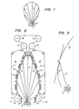
- Figures 1 and 2 show an apparatus for practicing the method of the invention.
- reference numeral 1 designates a supply of evaporated metal which is provided by scanning an electron beam onto a metal in a water- cooling copper hearth 2 which extends in the widthwise direction of a flexible belt-shaped support, web W.
- the metal vapor 1 diffuses and evaporates along evaporated metal flow lines as indicated by arrows 3 in Figure 1.
- a specific feature of the method of the invention is that, while the web W is being guided in such a manner as to form a curved loop above the hearth 2, a metal film layer is formed on the lower surface, facing the hearth 2, of the web W.
- FIG. 2 A structure for guiding the web W along the curved loop is shown in Figure 2.
- Guide rollers 4 through 9 are provided at points where the direction of run of the web W is to be changed with the guide rollers 4 through 9 directly supporting the web W.
- the rollers 4 and 5 and the rollers 8 and 9 form a rising path A of the web W and a falling path B of the web W, respectively, which are symmetrical with respect to the hearth 2.
- Endless-belt shaped curve forming mechanisms 10 and 10' are provided between the rollers 4 and 5 and between the rollers 8 and 9, respectively.
- the curve forming mechanism 10 and 10' have endless belts 11 and 11', respectively, each of which is formed as follows: Metal such as copper or aluminium is vacuum-deposited on the outer side of a plastic belt, on the inner side of which an iron film, a fine iron wire or iron powder is provided.
- the endless belts 11 and 11' thus formed are laid over a plurality of guide rollers 12 and 12', respectively.
- a plurality of magnets 13 and 13' are suitably disposed adjacent to the inner sides of portions of the endless belts 11 and 11' forming the above-described rising path A and falling path B of the web W, respectively.
- the magnets 13 and 13' continuously attract the endless belts 11 and 11' so that the belts curve along the rising path A and the falling path B, respectively.
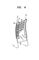
- Each of the endless belts 11 and 11' may be replaced by a caterpillar-type belt which is provided by connecting a number of elongated iron plates.
- the caterpillar-type belt as shown in Figure 4, it is also possible to guide the travel of the belts 16 along the rising path A and the falling path B in such a manner that each of the belts 16 at its surface confronting the evaporated metal flow lines is supported by means of a plurality of guide rollers 18 each rotatably supported to a pair of supporting plates 17. The both ends of each of the belts 16 are guided by these rollers 18.
- the web W running along the curved rising path A and the curved falling path B is electrostatically charged by a glow discharge process or the like before it confronts the hearth 2. Therefore, the web W is electrostatically attracted to the outer sides of the endless belts 11 and 11' in the rising path A and the falling path B so that it is guided in the form of a curve.
- the shape of the curve forming mechanisms 10 and 10' is determined as follows: As shown in Figure 3, the evaporated metal flow line 3' connecting the central point O of the evaporation surface of the metal vapor 1 to a given point X on the web W along the rising path A (or the falling path B) forms an angle L YXO with a line XY tangent to the point X.
- the curve forming mechanism is so designed that it conveys the web W with a curvature so as to maintain the angle L YXO constant in the longitudinal direction of the web W.
- shielding masks 15 and 15' be provided between the hearth 2 and the guide roller 4 and between the hearth 2 and the guide roller 9, respectively, and that a shielding mask 14 be disposed between the guide rollers 5 and 8 in order to eliminate difficulties in deposition quality which can be caused if the density of evaporated metal flow lines of the evaporated metal 1 is considerably too small or in areas where it is difficult to curve the web W so that the above-described incident angle is maintained.
- the web W is guided along the curves by the curve forming mechanisms 10 and 10' in such a manner that the evaporated metal flow lines connecting the central point 0 of the evaporation surface of the evaporated metal 1 in the hearth 2 to a given point on the web W form the same incident angle 0 with respect to the longitudinal direction of the web W.
- the efficiency of vacuum-deposition of the evaporated metal 1 is greatly improved and the resultant magnetic characteristic is uniform.
- the magnetic characteristics of a vacuum-deposited cobalt film formed according to a method proposed by Japanese Laid-Open Patent Application No. 9607/1979 among the above-described conventional methods, especially the anti-magnetic-force and rectangular ratio thereof were compared with those of a vacuum-deposited cobalt film formed according to the above-described method of the invention.
- the anti-magnetic-force and the rectangular ratio of the film according to the conventional method were 850 Oe and 0.91, respectively, while those of the film according to the method of the invention were 900 Oe and 0.95. Thus, it has been confirmed that the method of the invention provides excellent magnetic characteristic.
- metal such as Fe, Co or Ni may be employed as a ferromagnetic metal to form a magnetic film, or ferromagnetic alloys such as Fe-Co, Fe-Ni, Co-Ni, Fe-Co-Ni, Fe-Rh, Fe-Cu, Co-Cu, Co-Au, Co-Y, CoLa, Co-Pr, Co-Gd, Co-Sm, Co-Pt, Ni-Cu, Mn-Bi, Mn-Sb, Mn-Al, Fe-Cr, Co-Cr, Ni-Cr, Fe-Co-Cr, or Fe-Co-Ni-Cr may be employed.
- ferromagnetic alloys such as Fe-Co, Fe-Ni, Co-Ni, Fe-Co-Ni, Fe-Rh, Fe-Cu, Co-Cu, Co-Au, Co-Y, CoLa, Co-Pr, Co-Gd, Co-Sm, Co-Pt, Ni-Cu, Mn-Bi, Mn-Sb,
- the magnetic film should be thick enough to provide a sufficient output as a magnetic recording medium and thin enough for high density recording operations. Taking these considerations into account, in general, the thickness of the magnetic film should be in a range of from about 0.02 ,um to 5.0 ,um, preferably from 0.05 ⁇ m to 2.0 ,um.
- a plastic base support for instance, of polyethylene terephthalate, polyimide, polyamide, polyvinyl chloride, cellulose triacetate, poli- carbonate or polyethylene naphthalate may be employed as the support W.
- a resistance heating method, a laser beam heating method, a high frequency heating method or an electron beam heating method can be employed to heat the evaporation source in accordance with the invention.
- a method of feeding a linear material to the heating source may be employed to feed the evaporation material.
Landscapes
- Chemical & Material Sciences (AREA)
- Engineering & Computer Science (AREA)
- Power Engineering (AREA)
- Chemical Kinetics & Catalysis (AREA)
- Materials Engineering (AREA)
- Mechanical Engineering (AREA)
- Metallurgy (AREA)
- Organic Chemistry (AREA)
- Manufacturing & Machinery (AREA)
- Manufacturing Of Magnetic Record Carriers (AREA)
- Physical Vapour Deposition (AREA)
- Thin Magnetic Films (AREA)
Claims (19)
Applications Claiming Priority (2)
| Application Number | Priority Date | Filing Date | Title |
|---|---|---|---|
| JP66877/80 | 1980-05-20 | ||
| JP6687780A JPS56163526A (en) | 1980-05-20 | 1980-05-20 | Production of magnetic recording medium |
Publications (3)
| Publication Number | Publication Date |
|---|---|
| EP0040437A2 EP0040437A2 (de) | 1981-11-25 |
| EP0040437A3 EP0040437A3 (en) | 1982-05-26 |
| EP0040437B1 true EP0040437B1 (de) | 1984-10-31 |
Family
ID=13328537
Family Applications (1)
| Application Number | Title | Priority Date | Filing Date |
|---|---|---|---|
| EP81103899A Expired EP0040437B1 (de) | 1980-05-20 | 1981-05-20 | Herstellungsverfahren für ein magnetisches Aufzeichnungsmedium |
Country Status (4)
| Country | Link |
|---|---|
| US (2) | US4395439A (de) |
| EP (1) | EP0040437B1 (de) |
| JP (1) | JPS56163526A (de) |
| DE (1) | DE3166922D1 (de) |
Families Citing this family (8)
| Publication number | Priority date | Publication date | Assignee | Title |
|---|---|---|---|---|
| JPS59193542A (ja) * | 1983-04-15 | 1984-11-02 | Matsushita Electric Ind Co Ltd | 磁気記録媒体の製造方法 |
| JPS6173875A (ja) * | 1984-09-17 | 1986-04-16 | Mitsubishi Heavy Ind Ltd | 流路幅調整板付き真空蒸着装置 |
| DE3675270D1 (de) * | 1985-05-21 | 1990-12-06 | Toyoda Gosei Kk | Zerstaeubungsgeraet. |
| JPH06280026A (ja) | 1993-03-24 | 1994-10-04 | Semiconductor Energy Lab Co Ltd | 成膜装置及び成膜方法 |
| IT1269042B (it) * | 1994-03-18 | 1997-03-18 | Galileo Vacuum Tec Spa | Impianto continuo di metallizzazione sotto vuoto del tipo con due rulli delimitanti una zona di trattamento (configurazione free-span) |
| DE4438675A1 (de) * | 1994-10-29 | 1996-05-02 | Leybold Ag | Vorrichtung zum Aufdampfen von Schichten auf Folienbänder |
| WO2002086185A1 (en) * | 2001-04-20 | 2002-10-31 | Applied Process Technologies | Penning discharge plasma source |
| WO2004032120A1 (en) * | 2002-09-30 | 2004-04-15 | Seagate Technology Llc | Magnetic storage media having tilted magnetic anisotropy |
Family Cites Families (3)
| Publication number | Priority date | Publication date | Assignee | Title |
|---|---|---|---|---|
| LU69013A1 (de) * | 1973-03-07 | 1974-02-22 | ||
| JPS51149008A (en) * | 1975-05-23 | 1976-12-21 | Fuji Photo Film Co Ltd | Magnetic recording medium manufacturing method |
| GB1596385A (en) * | 1976-12-29 | 1981-08-26 | Matsushita Electric Industrial Co Ltd | Methods and apparatus for manufacturing magnetic recording media |
-
1980
- 1980-05-20 JP JP6687780A patent/JPS56163526A/ja active Pending
-
1981
- 1981-05-19 US US06/265,123 patent/US4395439A/en not_active Expired - Lifetime
- 1981-05-20 DE DE8181103899T patent/DE3166922D1/de not_active Expired
- 1981-05-20 EP EP81103899A patent/EP0040437B1/de not_active Expired
-
1983
- 1983-05-03 US US06/475,674 patent/US4446816A/en not_active Expired - Lifetime
Also Published As
| Publication number | Publication date |
|---|---|
| EP0040437A3 (en) | 1982-05-26 |
| US4395439A (en) | 1983-07-26 |
| EP0040437A2 (de) | 1981-11-25 |
| DE3166922D1 (en) | 1984-12-06 |
| JPS56163526A (en) | 1981-12-16 |
| US4446816A (en) | 1984-05-08 |
Similar Documents
| Publication | Publication Date | Title |
|---|---|---|
| EP0053811B1 (de) | Magnetische Aufzeichnungsmedien | |
| US4702938A (en) | Process for producing magnetic recording material | |
| US4412507A (en) | Magnetic recording medium manufacturing device | |
| US4501225A (en) | Apparatus for making a magnetic recording medium | |
| US4403002A (en) | Vacuum evaporating apparatus | |
| EP0040437B1 (de) | Herstellungsverfahren für ein magnetisches Aufzeichnungsmedium | |
| US4450186A (en) | Method and device for manufacturing magnetic recording medium | |
| US5679410A (en) | Continuous fabrication of thin film magnetic recording medium with vacuum deposition | |
| EP0099006B1 (de) | Diskette für senkrechte magnetische Aufzeichnung | |
| JPS5968815A (ja) | 磁気記録媒体 | |
| JPH0916960A (ja) | 情報記録媒体の製造装置 | |
| EP0468488A1 (de) | Verfahren zur Herstellung eines magnetischen Aufzeichnungsträgers | |
| EP0688016B1 (de) | Methode und Vorrichtung zur Herstellung eines magnetischen Aufzeichnungsmediums | |
| US4546725A (en) | Apparatus for manufacturing magnetic recording media | |
| US4526131A (en) | Magnetic recording medium manufacturing apparatus | |
| JPS5837842A (ja) | 磁気記録媒体の製造方法 | |
| US5122392A (en) | Method and apparatus for manufacturing magnetic recording medium | |
| JPS61187127A (ja) | 磁気記録媒体の製造方法 | |
| JPH0798831A (ja) | 磁気記録媒体、その製造方法及び製造装置 | |
| JPS6043915B2 (ja) | 真空蒸着方法 | |
| JPH0798832A (ja) | 磁気記録媒体、その製造方法及び製造装置 | |
| JPH10112024A (ja) | 磁気記録媒体の製造方法およびその製造装置 | |
| JPH103659A (ja) | 磁気記録媒体の製造装置及び方法 | |
| JPS6043916B2 (ja) | 真空蒸着法 | |
| JPS59178626A (ja) | 磁気記録媒体の製法 |
Legal Events
| Date | Code | Title | Description |
|---|---|---|---|
| PUAI | Public reference made under article 153(3) epc to a published international application that has entered the european phase |
Free format text: ORIGINAL CODE: 0009012 |
|
| AK | Designated contracting states |
Designated state(s): DE GB NL |
|
| PUAL | Search report despatched |
Free format text: ORIGINAL CODE: 0009013 |
|
| DET | De: translation of patent claims | ||
| AK | Designated contracting states |
Designated state(s): DE GB NL |
|
| 17P | Request for examination filed |
Effective date: 19821021 |
|
| GRAA | (expected) grant |
Free format text: ORIGINAL CODE: 0009210 |
|
| AK | Designated contracting states |
Designated state(s): DE GB NL |
|
| REF | Corresponds to: |
Ref document number: 3166922 Country of ref document: DE Date of ref document: 19841206 |
|
| PLBE | No opposition filed within time limit |
Free format text: ORIGINAL CODE: 0009261 |
|
| STAA | Information on the status of an ep patent application or granted ep patent |
Free format text: STATUS: NO OPPOSITION FILED WITHIN TIME LIMIT |
|
| 26N | No opposition filed | ||
| PGFP | Annual fee paid to national office [announced via postgrant information from national office to epo] |
Ref country code: GB Payment date: 19960514 Year of fee payment: 16 |
|
| PGFP | Annual fee paid to national office [announced via postgrant information from national office to epo] |
Ref country code: NL Payment date: 19960531 Year of fee payment: 16 |
|
| PGFP | Annual fee paid to national office [announced via postgrant information from national office to epo] |
Ref country code: DE Payment date: 19960628 Year of fee payment: 16 |
|
| PG25 | Lapsed in a contracting state [announced via postgrant information from national office to epo] |
Ref country code: GB Effective date: 19970520 |
|
| PG25 | Lapsed in a contracting state [announced via postgrant information from national office to epo] |
Ref country code: NL Effective date: 19971201 |
|
| GBPC | Gb: european patent ceased through non-payment of renewal fee |
Effective date: 19970520 |
|
| NLV4 | Nl: lapsed or anulled due to non-payment of the annual fee |
Effective date: 19971201 |
|
| PG25 | Lapsed in a contracting state [announced via postgrant information from national office to epo] |
Ref country code: DE Free format text: LAPSE BECAUSE OF NON-PAYMENT OF DUE FEES Effective date: 19980203 |