EP0043201A1 - Système de commande de processus industriel - Google Patents
Système de commande de processus industriel Download PDFInfo
- Publication number
- EP0043201A1 EP0043201A1 EP81302678A EP81302678A EP0043201A1 EP 0043201 A1 EP0043201 A1 EP 0043201A1 EP 81302678 A EP81302678 A EP 81302678A EP 81302678 A EP81302678 A EP 81302678A EP 0043201 A1 EP0043201 A1 EP 0043201A1
- Authority
- EP
- European Patent Office
- Prior art keywords
- control
- area
- visual display
- touching
- signal
- Prior art date
- Legal status (The legal status is an assumption and is not a legal conclusion. Google has not performed a legal analysis and makes no representation as to the accuracy of the status listed.)
- Granted
Links
Images


Classifications
-
- G—PHYSICS
- G06—COMPUTING OR CALCULATING; COUNTING
- G06F—ELECTRIC DIGITAL DATA PROCESSING
- G06F3/00—Input arrangements for transferring data to be processed into a form capable of being handled by the computer; Output arrangements for transferring data from processing unit to output unit, e.g. interface arrangements
- G06F3/01—Input arrangements or combined input and output arrangements for interaction between user and computer
- G06F3/03—Arrangements for converting the position or the displacement of a member into a coded form
- G06F3/033—Pointing devices displaced or positioned by the user, e.g. mice, trackballs, pens or joysticks; Accessories therefor
-
- G—PHYSICS
- G05—CONTROLLING; REGULATING
- G05B—CONTROL OR REGULATING SYSTEMS IN GENERAL; FUNCTIONAL ELEMENTS OF SUCH SYSTEMS; MONITORING OR TESTING ARRANGEMENTS FOR SUCH SYSTEMS OR ELEMENTS
- G05B19/00—Program-control systems
- G05B19/02—Program-control systems electric
- G05B19/18—Numerical control [NC], i.e. automatically operating machines, in particular machine tools, e.g. in a manufacturing environment, so as to execute positioning, movement or co-ordinated operations by means of program data in numerical form
- G05B19/409—Numerical control [NC], i.e. automatically operating machines, in particular machine tools, e.g. in a manufacturing environment, so as to execute positioning, movement or co-ordinated operations by means of program data in numerical form characterised by using manual data input [MDI] or by using control panel, e.g. controlling functions with the panel; characterised by control panel details or by setting parameters
-
- G—PHYSICS
- G05—CONTROLLING; REGULATING
- G05B—CONTROL OR REGULATING SYSTEMS IN GENERAL; FUNCTIONAL ELEMENTS OF SUCH SYSTEMS; MONITORING OR TESTING ARRANGEMENTS FOR SUCH SYSTEMS OR ELEMENTS
- G05B2219/00—Program-control systems
- G05B2219/30—Nc systems
- G05B2219/32—Operator till task planning
- G05B2219/32128—Gui graphical user interface
-
- G—PHYSICS
- G05—CONTROLLING; REGULATING
- G05B—CONTROL OR REGULATING SYSTEMS IN GENERAL; FUNCTIONAL ELEMENTS OF SUCH SYSTEMS; MONITORING OR TESTING ARRANGEMENTS FOR SUCH SYSTEMS OR ELEMENTS
- G05B2219/00—Program-control systems
- G05B2219/30—Nc systems
- G05B2219/36—Nc in input of data, input key till input tape
- G05B2219/36168—Touchscreen
Definitions
- the present invention relates to a computer controlled system for an industrial process and, more particularly, to a computer controlled system for an industrial process in which interactive control by a human operator is achieved through a touch-responsive visual display.
- the man/machine interface has been typically accomplished with a cathode ray tube (CRT). visual display device in combination with a standardized keyboard.
- CTR cathode ray tube
- visual display device in combination with a standardized keyboard.
- the system operator usually must enter a code, such as an alpha-numeric acronym or mnemonic, and then enter another code for the command to effect the requested information display, change in the operation of the. controlled device, and/or change the set point of a system parameter. Because the entry of this type. of information requires correct depression of a sequence of key pads, keyboard entry of commands is dependent upon the skill of the system operator and is, of course, subject to error.
- An industrial process in accordance with a preferred embodiment of the present invention includes a plurality of process control devices each connected for control thereof to an associated device controller.
- a common communications buss interconnects the device controllers with a command and information interface means to permit communication therebetween.
- the command and information interface is provided for entering commands, requests, information, and the like into the system and includes a visual display device such as a cathode ray tube (CRT) and a computer means for generating alpha-numeric characters for information display and pictorial symbols which graphically represent the controlled devices of the process.
- the displayed symbols can include graphical representations of push buttons as well as more definite symbols such as a graphical representation of a pump or the like.
- a transparent or otherwise light transmitting touch-responsive panel overlies the CRT screen so that the CRT display surface will be in. substantial registration with the touch-responsive panel.
- System commands including sequential-type commands as well as analog-type commands, are entered, by manually touching an area of the touch-responsive screen in which a symbol appears.
- the displayed symbol Upon entry of the command, the displayed symbol then changes in a selected manner, e.g., the color of the displayed. symbol is changed, to indicate that the controlled device has responded in the input command.
- Other features of the invention include the display of.
- a "hit" indicia to indicate the last position touched by the operator on the screen
- a two-step entry procedure for inputting high priority control signals to guard against error
- the industrial process control. system in accordance with the present invention advantageously permits a, system operator to enter commands, requests, display information, and the like in a manner by which the touch-responsive command entry area is in spatial registration or juxtaposition with a visual symbol of the controlled device to which the command pertains. In this way, commands and the like can be easily entered with a low error rate.
- the need for entry through a keyboard is minimized and may be eliminated in some applications to provide efficient, high-level system control,
- the possibility of mis-strike on the screen is greatly reduced when. compared to the possibility of mis-strike in conventional keyboard entry systems.
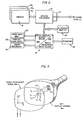
- FIG. 1 An industrial control system in accordance with the present invention is shown in schematic form in FIG. 1 and includes a communications link CL having a plurality of remotely located device controllers DC 1 , DC 2 , DC 3 ,...DC n-1 , DC n connected thereto with each of the device controllers DC n connected to one or more associated or corresponding controlled devices CD 1 , CD 2 , CD 3 ,...CD n-1 , CD n such as, but not limited to, various types of parameter sensors (temperature, position pressure, and motion sensors, etc.) and various types of controlled devices (motors, pumps, compressors, valves, solenoids, and relays, etc.).
- various types of parameter sensors temperature, position pressure, and motion sensors, etc.
- controlled devices motors, pumps, compressors, valves, solenoids, and relays, etc.
- a system controlling interface 10 is also connected to the communications link 'CL and provides a means by which signals (including information and control signals) may be extracted from or entered into the process control system.
- the system configuration shown in F IG. 1 is a distributed open loop or shared global buss-type; however, the invention is equally suitable for application to central systems and central/distributed hybrid configurations.
- the system of FIG. 1 is adapted for.use in controlling an industrial process, e.g., the operation of an electrical power generation plant.
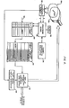
- FIG. 2 The organization of an exemplary system control interface 10 is shown in FIG. 2 and includes a system processor 12 connected to the communications link CL through an appropriate input/output interface 14 and a memory 16 connected to the system processor 12.
- the memory 16 includes plural memory files M 1 , M 2 ,...M n which contain appropriate instruction sets and stored data for use in controlling the system operation.
- a combined video output and tactile input device 18 is connected to the system processor 12 and functions as a man/machine interface as described more fully below with at least one auxiliary or alternate visual display device 20 also connected to the sytem processor 12.
- a printer 22 is connected to the visual output and tactile input device 18 to provide a hard copy of alpha-numeric information or data such as alarm status information and a video copy unit 23 is also connected to the visual output and tactile input device 18 for providing a hard copy of the current video display.
- a chart recorder 24 is provided for obtaining a graphical output of a parameter(s) with respect to time.
- a keyboard 26 is provided for auxiliary input of alpha-numeric data as described below.
- the video display output and tactile input device 18 is shown in pictorial form in FIG. 3 and includes a cathode ray tube (CRT) having a conventional display screen 18a or surface and a touch-responsive panel 18b that overlies the display screen. While not specifically shown in FIG. 3, the CRT is connected to the necessary structure and circuitry for the generation of full-color displays as described more fully below.
- the touch-responsive device 18b preferably takes the form of a light transmitting (preferably transparent) panel that is placed over and overlies the display screen 18a of the CRT and conforms closely to the display surface of the CRT.
- the touch-responsive panel 18b may be a flexible, transparent sheet-like panel fabricated from an insulating material such as Mylar with a light-transmitting conductive coating deposited thereon of uniform resistivity.
- Plural electrodes (not shown) are deposited or otherwise formed along the horizontal and vertical edges of the touch-responsive panel and connected to a power supply(s) to develop perpendicular electric fields across the conductive coating so that when a surface portion thereof is touched by a human operator, a signal is derived from the various electrodes which can be decoded or otherwise discriminated to provide the coordinates (X,Y) of the touched area.
- the touch-responsive panel may also take the form of a plurality of spaced parallel conductive traces arranged in columns and perpendicular rows with these rows and columns separated by a suitably apertured dielectric media to define a direct- contact switch matrix.
- the various rows and columns may be sequentially and synchronously scanned and electrical contact between a row'(s) and a column(s) detected as a touch and these contact areas when correlated with the scanning information, providing the coordinates (X,Y) that indicate the location of the touched area on the display.
- the symbol of. a control valve CV can be graphically represented on the CRT screen.
- the symbol CV occupies a corresponding surface area CV' of the touch-responsive panel 18b with this area being identified along the X-axis (abscissa) between the coordinates x 1 and x 2 and along the Y-axis (ordinate) between the coordinates y 1 , and y 2 .
- a human, operator touches the touch-responsive panel 18b at a position (X,Y) within the control valve 'CV' "target" area (that is, x 1 ⁇ X ⁇ x 2 and y 1 ⁇ Y ⁇ y 2 ), the touch or "hit" will be within the area defined by. the symbolically represented control valve CV.
- this coordinate information (X,Y) can be employed by the system processor 12 to provide command inputs to the system to effect a change in the control valve operation.
- the system of FIGS. 1-3 can be utilized to permit the system operator to call-up selected displays as well as effect control of the system.-
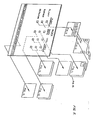
- the manner in which the system can be used for display call-up can be appreciated from a consideration of the system architecture shown in FIG. 4.
- the display processor 30 which, in the. case of the preferred embodiment, is an Intel 8086 microprocessor with an associated clock. 32 and support integrated circuits (not shown).
- the processor 30, operating under the control of an.
- instruction set 34 that evaluates the touched target, assesses the formatted X, Y coordinate information .to provide a X, Y display-label look-up pointer, symbolically represented at 36.
- the pointer 36 is used to designate or address the X, Y display-label table 38 which then provides an address (e.g., "INDEX") to the display look-up table 40.
- the so-addressed display sub-routine i.e., "INDEX”
- a display ganerator 42 which generates the called-up display.
- a, "HIT" indicator display generator 44 uses the formatted coordinate information (X,Y) to generate a small cross symbol ''+" so that the system operator (s) will always be informed of the last target area touched.
- FIG. 6 An exemplary process for control by the industrial process control system of FIG. 1 involves the removal of sulfur from sulfur-containing fuel oil prior to using the so-treated oil to fire a conventional steam generator; it being understood the described process is merely representative.
- Selected overall displays associated with this process and suitable for . use in demonstrating the present invention are shown in FIGS. 6-12. Each overall display includes two portions: a lower global. display portion and an upper task-specific portion.
- FIG. 6 illustrates the global display, which is common to all of the displays, and shows a horizontal row of hollow, labelled target rectangles for effecting an input into the system.
- Exemplary touch-responsive rectangles include "INDEX,” “ALARMS,” “ALT” (an abbreviation for 'alternate'), “CLEAR,” “PAGE,” “BACK,” “ALM SUM” (an abbreviation for 'alarm summary'), “RETURN,” “COPY,” and “EXE” (an abbreviation for 'execute').
- the "INDEX” target is used to call-up the first page of a multi-page 'index' file; the ''ALARMS” target is used to acknowledge all unacknowledged alarms on a-currently displayed page of the 'alarm summary' file (described in more detail below); the "ALT” target is used. to control the alternate display 20 of FIG. 2; the "CLEAR” target is used to clear (that is, remove) the current display on the screen; the ''PAGE” target is used to increment by one.
- the "BACK” target is used to decrement by one the page of the currently displayed file;
- the "ALM SUM” target is used to call-up the first page of the 'alarm summary' file;
- the "RETURN” target is used to return the display to the first page of the last successive display from an "N" deep display stack;
- the "CPY” target is used to actuate. the printed 22 of FIG. 2 to provide a hard copy of the display; and the "EXE” target is used in the entry of two-step commands as described more fully below.
- Touching the "INDEX" target of the global display causes formatted coordinate information (X,Y) indentifying the touched area to be. provided to the system processor 30 of FIG. 4. These coordinates are then used to generate a look-up pointer 36 for appropriate display label (INDEX) in the display table look-up table. 38 with the so-looked up label used to address the appropriate set of display-generation instructions (INDEX) in the instruction table 40. These instructions then are provided to the display generator 42 which then provided the requested display (INDEX) on the cathode ray tube screen 18a.
- the indicia display generator 44 uses the formatted coordinate information to display a cross symbol '"+" in the touched area. In this way, the system operator (s) will always be informed of the last target area touched on. the touch-responsive panel 18b.
- the first page of the .'index' file called-up in response to touching the "INDEX" target of the global display is shown in FIG. 7 and, as shown therein, includes a plurality of labelled target rectangles.
- An exemplary second page of the 'index' file is shown in FIG. 8 and, as in the case of the first page shown in FIG. 7, also includes a plurality of labelled target rectangles.
- the second page of the 'index' display is accessed by.touching the "PAGE" target of the global'display to cause the display to increment one page in the 'index' file.
- the pages of the 'index' file, as well. as the othe display files discussed below are looped end-to-start so that incrementing past the last page of the display will cause the display to go to the first page of the file.
- the lower portion of the 'index' display includes the following target areas:
- each of which include a plurality of bar graphs (G1-G8) distributed along a horizontal line in each rectangle.
- the various bar graphs (G1-G8) in each of the labelled rectangles represent a selected parameter including an analog parameter (e.g., the deviation of a measured value. 'from: a set point or the relative position of an adjustable, controlled device) or a digital parameter (e.g., the open or closed position, of a valve).
- the bar graphs G1-G8 are colored differently from one another, and, if desired displayed at different brightness levels.
- the display brightness of some of the bar graphs viz., those that are. in an alarm condition., can cycle between two different brightness levels to provide a blinking or flashing effect.
- Each of the labelled rectangles of FIG. 9. constitutes a target area for calling up another display.
- the system operator(s) requires additional information regarding the parameters of one of the "LABEL-2" bar-graph target rectangles of FIG. 9, he merely touches that bar-graph rectangle to call-up the appropriate 'process control' file having the format shown in FIG. 10.
- the 'process control' file of FIG. 10 includes five sets of vertically aligned and labelled bar graphs with each set including three individual bar graphs G'1-G'3 in a side-by- side relationship.
- two push-button target areas are provided on each side of the bar graph sets with the left-hand push button area PB1 representing ON/OFF control and the right-hand pushbutton area PB2 representing a system safety control including an "ARMED" target.area and a "TRIPPED" target area.
- the bar graph sets of FIG. 10 each. represent the output of a control loop. In the representative bar graph groups of FIG. 10, each.
- left-hand bar graph G'1 represents the magnitude of the measured value of a selected parameter
- the intermediate bar graph G'2 represents the magnitude of the desired set point for that measured parameter
- the right-hand bar graph represents the operative position of an associated controlled device.
- the right-hand bar graph 'G'-3 can represent the analog position of a valve as a function of the height of the bar graph G'3.
- various control information is provided including quantitative alpha-numeric. information as to the set point and measured value of a parameter and an indication-of the status of the respective PID (Proportional-Integral-Differential) control loop, that is, whether or not the associated PID loop is under the control of the system operator (e.g. manual control indications) or responsive to the output of another loop (e.g. cascade indications).
- PID Proportional-Integral-Differential
- the touch-responsive panel 18b and the 'process control' display of FIG. 10 can be used to effect entry of commands of both a digital and analog nature.
- ' digital-type commands may be entered by touching the "START" target rectangle on the left-hand side of the display of FIG. 10.
- Appropriate coordinate (X,Y) information in formatted form is presented to the processor 30 (FIG. 4) which then evaluates the coordinate information to generate an appropriate START-command.
- the "EXE" target is touched to provide the actual START control signal to the appropriate controlled device (e.g. a pump).
- touching the STOP rectangle causes a STOP command to be generated with subsequent touching of the "EXE”target causing the STOP control signal to be provided to the controlled device.
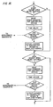
- analog-type commands such as changing' the set point of selected parameter for one of the loops; the upper portion, of the appropriate bar graph, set or the other designated area, for example, the area ATA-I (Analog Target Area-Increment) shown in the dotted line illustration in FIG, 10 is touched.
- the coordinates information in formatted form is provided to the processor 30 (FIG. 4) which then continuously increases the set point toward a maximum value for as long as the target area ATA-I is touched. For example., briefly touching the ATA-I area of the set point bar graph G'2 will: cause that set point to increase a small amount, and touching the same target area ATA-I for a longer period of time will cause the set point to increase proportionally.
- the set point will then cause a resultant increase 'in the vertical height of the set point bar graph G'2.
- the set point may be lowered by touching a designated area ATA-D (Analog Target Area-Decrement) as shown in dashed line below the set point bar graph G'2 with the set point being continuously lowered toward a minimum value for as long as the area ATA-D is touched.
- The. change in the set point will then cause a resultant decrease in the vertical height of the set point bar graph G'2.
- the set point may be raised and lowered in a very simple manner by merely torching, for the required amount of time, the appropriate target area ATA-I or ATA-D with the requested change in the set point being visually displayed to the system operator by the graph G'2 and the change in the measured value thereafter being indicated by the associated graph G'1.
- An exemplary flow diagram representing an instruction set for effecting the above described increment/decrement analog-type command signal entry and the subsequent change in the set point is shown in FIG. 17.
- the display of FIG. 10 also includes, as shown therein, selected numerical information relating to the controlled loop and other information indicating the particular mode the loop is operating in, as explained below.
- the display of FIG. 10 is also used by the system operator (s) to change the 'overall control loop configuration.
- Each of the PID loops may be placed in one of several operating modes including a 'cascade' of 'single' mode and a 'manual' or 'auto mode.
- the 'cascade' mode permits a loop to receive, as its input, the output of another PID loop, while the 'single' mode permits that same loop to operate in response to a predetermined set point, and the ''manual'' mode permits the loop to operate as an open-loop follower without loop control, while the ''auto" mode permits that same loop to operate as a closed loop.
- a particular PID loop can be switched between the "cascade", and "single" modes by. touching the target area DTA-C/S- [Digital Target Area-Cascade/Single) shown in dotted line illustration below the appropriate bar graphs.
- a small hit indicia "+” will then be displayed in the touched target area and, if desired, the. brightness of the touched DTA-C/S target area can be made to cyclically vary between two brightness levels to provide a flashing or blinking effect.
- the operator touches the '"EXE" target of the global display to enter the command.
- the selected PID loop is then changed from its present mode (e.g., the 'cascade' model to the other available mode (e.g., the "single'' mode).
- the system operator can switch. a selected PID loop Between the "manual” and “auto'' modes by touching the DTA-M/A (Digital Target Area-Manual/Auto) under the appropriate Bar graph set.
- a hit indicia (+) will then be displayed in the touched target area and thereafter, the operator touches the "EXE" target of the global. display to enter the command; the selected PID loop being then placed in the desired mode (e.g., manual, or auto).
- the "PROCESS GRAPHIC" target areas of the 'index' display of FIG, 7 will call-up graphical representations of the process. For example, touching the "PROCESS GRAPHIC" target area for the "PESULFUR” portion of the 'index' display will call-up the first page of a graphic display file as shown in FIG. 11 with the second page of the file (FIG. 12) available for display by touching the "PAGE" target area of the global display.
- the exemplary process shown in FIGS. 11 and 12 removes sulfur from input fuel oil by mixing the fuel oil with hydrogen gas, heating the fuel oil and hydrogen mixture, and then passing the so-heated mixture over a catalyst bed where the hydrogen combines with the sulfur in the fuel oil to form hydrogen sulfide gas and the desired desulfured fuel oil.
- the controlled devices for effecting the desulfurization of the fuel oil include a feed pump 100 which receives fuel oil from an input line 102 and delivers the fuel oil under pressure along line 104 through a flow meter 106, a flow control valve 108, and a safety valve 110. Hydrogen gas is provided along line 112 and is mixed with the feed oil at junction 108.
- the temperature of the gas/oil mixture is measured by sensor 114 and the mixture; passed through a heat exchanger 116 where the mixture is preheated and then passed into a main heater 118 through line. 120 that includes a thermal sensor 122 and a control valve 124.
- the heated mixture is passed to a catalyst bed 126 which contains a catalyst that causes the hydrogen gas to react with sulfur contained in the fuel oil to form hydrogen sulfide gas and desulfured feed oil.
- This mixture is then provided along outlet line 128 past pressure sensor 130 and temperature sensor 132 to the heat exchanger 116 where heat energy from the mixture is provided to the incoming fuel oil and hydrogen gas mixture.
- the somewhat cooler mixture is then conducted along line 134 past temperature sensor 136 to the apparatus shown on the second page of the 'process graphic' display.
- the second page of the 'process graphic display (FIG. 12) is called-up by touching the "PAGE" target area of the global displays.
- the fuel oil mixture is passed to another heat exchanger 138 where additional heat energy is removed and past a temperature sensor 140 to a gas/liquid separator 142.
- the separator 142 the. hydrogen sulfide gas is removed along line 144 through valve 146 with its flow rate and pressure being measured at 148 and 150.
- the desulfured fuel oil is removed along discharge line 152 through valve 156 with the flow rate Being measured at 158.
- a line 160 with pressure and flow rate sensors 162 and 164 is provided through, which recycled process gas is provided to the burners 166 of the. heater 118 (FIG. 11) with the flow- being controlled at valve 168.
- a bar graph rectangle is shown in the upper left-hand side of FIG. 11 and illustrates various parameters in bar graph form for the process shown in the remaining portion of FIG. 11.
- the bar graph area is also a target area and, when touched, will. call-up the display of FIG. 10 to permit the system operator to effect control changes within the system as described above.
- the operation of the burner area of FIG. 11. may be shown in greater detail by depressing the appropriate process graphic target area for the burner on the index page 'to provide the display shown in FIG. 13..
- the 'burner' display includes the burners 166 which selectively receive fuel gas along line 170, fuel oil along line 172, pressurized steam along line 174, and fuel for the burner pilot along line 176.
- the fuel lines 170 and 172 both include control valving and pressure and temperature sensors that provide inputs to the associated PID loops.
- the 'process control' display of FIG, 10 directly corresponds with the process graphics of FIGS, 11-13, More specifically, the 'push button control area PB1 on the left-hand side of FIG. 10 controls the operation of the feed pump 100.
- FIG. 11 with the three-bar, graph set of FIG. 10.
- labelled 'product oil feed' indicating the flow rate of the feed oil through line 104 in relation to the desired set point.
- the three-bar graph set of FIG. 10 labelled 'burner temperature' illustrates the measured temperature of the burners 166 of FIGS. 11 and 12 in relationship to their desired set point.
- the two three-bar graph sets labelled 'fuel oil pressure' and 'fuel gas pressure' graphically illustrate the measured and set point values for the fuel in lines 170 and 172, respectively, of PIG. 13 while the three-bar graph set labelled 'atomization steam pressure' indicates the pressure of the steam in line 174.
- pressurized steam is introduced with fuel oil to assist in atomizing the fuel oil.
- fuel gas is a preferred fuel with fuel oil and associated steam being used when desired or when dictated by operating circumstances.
- commands inputted to the appropriate target areas of FIG. 10 directly control the various control devices discussed above in connection with FIGS. 11-13.
- the "LOG" target areas of the 'index' file (FIG. 71 for the "PIANT,” “BURNER,” and “PESULFUR” portions of the process provide a time-tagged listing of events in the process. While a 'log' display hs not been illustrated in the figures, a typical 'log' display would include a listing of command changes and other events along with the time and date that these changes or events occurred. If desired, a cumulative log can be printed on the printer 22 (FIG. 2) at periodic intervals, e.g., every hour-on-the-hour to provide an historical recoard of the process.
- the "AREA SUMMARY" target area of the 'index' file calls-up a display with a current status information of various of the control loops and other parameters.
- An exemplary 'area summary' display shown in FIG. 15 and-as shown therein includes an alpha-numeric identifier for the control loop or parameter, a short explanatory title, the quantitative value, and the associated units.
- the "ALARM SUMMARY" target area of the global display (FIG. 7). is used to call-up a listing of those parameters or control loop outputs that are or have been in an alarm condition (that is, the measured value 'is either above or below a predetermined alarm limit).
- An exemplary alarm summary' display is shown in FIG. 15 and includes time and. date information to indicate when the particular parameter entered the alarm condition, an alpha-numeric identifier, a short explanatory title, the quantitative value, and the associated units.
- Those particular parameters that are in alarm condition in the display of FIG. 15 may be highlighted for the operator's attention by varying their brightness leyel between two values to provide a blinking or flashing effect.
- the system operator may touch the "ALARMS" target area of the global display to acknowledge the alarms and to cause the blinking or flashing to stop. In this way, the operator, by periodically acknowledging alarms, can identify those parameters which most recently enter the alarm condition.
- the "ALT" target of the global display controls the display shown on the alternate 'display device 20 (FIG. 2). For example, touching the "ALT" target area and then touching the "COPY” target area will cause the printer 22 (FIG. 2) to provide a hard copy of the display shown on the alternate display device 20. Also, touching the "ALT" target area followed by touching the target areas “CLEAR,” “PAGE,” or “BACK” would cause these functional responses, to take place on the alternate display. Thus, by use of the "ALT" target, different displays can be called up for the visual display device 18a and the alternate display 20.
- an industrial process control system in accordance with present invention permits a system operator to effect quick and accurate control of an entire system by merely touching the- appropriate area on a visual display screen.
- the controlled devices of the system and parameters are graphically and symbolically displayed or the screen and the command input device is spatially juxtaposed with the displayed symbols so that command inputs, including command inputs of both an analog and digital nature, can be easily and quickly entered into the system.
Landscapes
- Engineering & Computer Science (AREA)
- General Engineering & Computer Science (AREA)
- Human Computer Interaction (AREA)
- Physics & Mathematics (AREA)
- General Physics & Mathematics (AREA)
- Theoretical Computer Science (AREA)
- Manufacturing & Machinery (AREA)
- Automation & Control Theory (AREA)
- Testing And Monitoring For Control Systems (AREA)
- Control By Computers (AREA)
- Digital Computer Display Output (AREA)
Applications Claiming Priority (4)
| Application Number | Priority Date | Filing Date | Title |
|---|---|---|---|
| US159599 | 1980-06-16 | ||
| US06/159,599 US4396977A (en) | 1980-06-16 | 1980-06-16 | Industrial process control system |
| US06/255,842 US4413314A (en) | 1980-06-16 | 1981-04-20 | Industrial process control system |
| US255842 | 2002-09-26 |
Publications (2)
| Publication Number | Publication Date |
|---|---|
| EP0043201A1 true EP0043201A1 (fr) | 1982-01-06 |
| EP0043201B1 EP0043201B1 (fr) | 1984-10-10 |
Family
ID=26856108
Family Applications (1)
| Application Number | Title | Priority Date | Filing Date |
|---|---|---|---|
| EP81302678A Expired EP0043201B1 (fr) | 1980-06-16 | 1981-06-16 | Système de commande de processus industriel |
Country Status (4)
| Country | Link |
|---|---|
| US (1) | US4413314A (fr) |
| EP (1) | EP0043201B1 (fr) |
| CA (1) | CA1185683A (fr) |
| DE (1) | DE3166579D1 (fr) |
Cited By (7)
| Publication number | Priority date | Publication date | Assignee | Title |
|---|---|---|---|---|
| DE3318512A1 (de) * | 1982-05-21 | 1983-12-01 | Mitsubishi Denki K.K., Tokyo | Numerische steuereinrichtung |
| EP0189026A2 (fr) | 1981-06-16 | 1986-07-30 | Forney International, Inc. | Système d'écran tactile |
| EP0438173A3 (fr) * | 1990-01-19 | 1994-03-09 | Yamatake Honeywell Co Ltd | |
| EP0340293B1 (fr) * | 1987-10-14 | 1995-05-17 | Pacesetter AB | Systeme de programmation et de diagnostic interactif destine a etre utilise avec un stimulateur cardiaque implantable |
| FR2772881A1 (fr) * | 1997-12-24 | 1999-06-25 | Alpes Systeme Automation | Dispositif de distribution d'un gaz de travail et installation de fourniture d'un gaz de travail equipee d'un tel dispositif |
| CN1304936C (zh) * | 1996-10-07 | 2007-03-14 | 霍尼韦尔公司 | 直观显示对象文件的仿真器及其操作方法 |
| EP3046010A1 (fr) * | 2015-01-19 | 2016-07-20 | Honeywell International Inc. | Système et procédé permettant de protéger des cibles tactiles critiques et d'urgence |
Families Citing this family (163)
| Publication number | Priority date | Publication date | Assignee | Title |
|---|---|---|---|---|
| US5338157B1 (en) * | 1992-09-09 | 1999-11-02 | Sims Deltec Inc | Systems and methods for communicating with ambulat |
| US6241704B1 (en) | 1901-11-22 | 2001-06-05 | Sims Deltec, Inc. | Drug pump systems and methods |
| JP2870384B2 (ja) * | 1993-11-10 | 1999-03-17 | 村田機械株式会社 | ワインダの運転条件設定装置 |
| US4521870A (en) * | 1981-04-09 | 1985-06-04 | Ampex Corporation | Audio/video system having touch responsive function display screen |
| DE3174280D1 (en) * | 1981-12-29 | 1986-05-07 | Ibm | Management system of displayable and descriptive data |
| CA1183609A (fr) * | 1982-03-29 | 1985-03-05 | Bruce S. Allen | Interface homme-machine |
| US4570217A (en) * | 1982-03-29 | 1986-02-11 | Allen Bruce S | Man machine interface |
| DE3220622A1 (de) * | 1982-06-01 | 1983-12-15 | M.A.N.- Roland Druckmaschinen AG, 6050 Offenbach | Dateneingabeeinrichtung an druckmaschinen |
| GB2130837B (en) | 1982-10-01 | 1987-04-23 | Canon Kk | Facsimile processing control |
| JPS5962947A (ja) * | 1982-10-01 | 1984-04-10 | Fanuc Ltd | 数値制御方式 |
| JPS5976718A (ja) * | 1982-10-25 | 1984-05-01 | Fanuc Ltd | ワイヤカツト放電加工条件設定方式 |
| JPS59116897A (ja) * | 1982-12-23 | 1984-07-05 | 株式会社東芝 | デイジタルコントロ−ラ |
| US4641269A (en) * | 1983-01-26 | 1987-02-03 | Emhart Industries, Inc. | Programmable control system for glassware forming machines |
| JPS59174714A (ja) * | 1983-03-25 | 1984-10-03 | Nippon Denso Co Ltd | 地図表示装置 |
| WO1984003944A1 (fr) * | 1983-03-28 | 1984-10-11 | Hitachi Construction Machinery | Instrument de mesure d'une valeur numerique utilisant un oscilloscope |
| JPS59183412A (ja) * | 1983-04-01 | 1984-10-18 | Fanuc Ltd | 数値制御用機械操作盤 |
| JPS59183428A (ja) * | 1983-04-01 | 1984-10-18 | Hitachi Ltd | 手書き入出力表示装置及び手書き入出力表示装置の表示方法 |
| JPS6066298A (ja) * | 1983-09-21 | 1985-04-16 | キヤノン株式会社 | 情報処理装置 |
| JPS6083132A (ja) * | 1983-10-14 | 1985-05-11 | Toshiba Corp | タッチスイッチ付表示装置 |
| US4587630A (en) * | 1984-02-15 | 1986-05-06 | Hewlett-Packard Company | Intelligent programmable touchscreen system |
| US4586035A (en) * | 1984-02-29 | 1986-04-29 | International Business Machines Corporation | Display terminal with a cursor responsive virtual distributed menu |
| JPS60207923A (ja) * | 1984-03-31 | 1985-10-19 | Toshiba Corp | 位置検出装置 |
| US4885575A (en) * | 1984-05-07 | 1989-12-05 | Williams Leon G | Method and means of displaying information |
| US4648028A (en) * | 1984-08-31 | 1987-03-03 | General Electric Co. | Color enhanced display for a numerical control system |
| US4847785A (en) * | 1985-01-22 | 1989-07-11 | International Business Machines Corp. | Interactive display for trend or bar graph |
| US4710758A (en) * | 1985-04-26 | 1987-12-01 | Westinghouse Electric Corp. | Automatic touch screen calibration method |
| US4812125A (en) * | 1985-05-29 | 1989-03-14 | Sony Corporation | Interactive teaching apparatus |
| FR2585145B1 (fr) * | 1985-07-16 | 1988-02-19 | Wanner Jean Claude | Procede et systeme de surveillance d'une installation industrielle |
| GB2181627B (en) * | 1985-09-10 | 1989-12-28 | Interactive Tech Limited | Information processing system |
| DE3542585A1 (de) * | 1985-12-02 | 1987-06-04 | Kraftwerk Union Ag | Kraftwerkswarte |
| US4720805A (en) * | 1985-12-10 | 1988-01-19 | Vye Scott R | Computerized control system for the pan and tilt functions of a motorized camera head |
| US4727473A (en) * | 1986-01-02 | 1988-02-23 | Fischer & Porter Company | Self-learning mechanism for a set of nested computer graphics |
| CH665999A5 (fr) * | 1986-03-17 | 1988-06-30 | Bobst Sa | Procede et dispositif pour commander le reglage des organes d'une machine pour les arts graphiques et le cartonnage. |
| US4794386A (en) * | 1986-04-11 | 1988-12-27 | Profit Technology, Inc. | Data integrator for video display including windows |
| US5032978A (en) * | 1986-05-05 | 1991-07-16 | Westinghouse Electric Co. | Status tree monitoring and display system |
| USRE38419E1 (en) | 1986-05-13 | 2004-02-10 | Ncr Corporation | Computer interface device |
| US7864151B1 (en) | 1986-07-07 | 2011-01-04 | Semiconductor Energy Laboratory Co., Ltd. | Portable electronic device |
| EP0252646B1 (fr) * | 1986-07-07 | 1993-09-29 | Semiconductor Energy Laboratory Co., Ltd. | Livre portable sans papier |
| WO1988000371A1 (fr) * | 1986-07-07 | 1988-01-14 | Newex, Inc. | Dispositif de commande peripherique |
| US4772882A (en) * | 1986-07-18 | 1988-09-20 | Commodore-Amiga, Inc. | Cursor controller user interface system |
| JPS6361597A (ja) * | 1986-09-01 | 1988-03-17 | Mitsubishi Electric Corp | 遠方監視制御装置の親局装置 |
| JPS63170780A (ja) * | 1986-10-03 | 1988-07-14 | インタランド・コーポレーション | 一体化したマルチ・ディスプレイ型のオーバーレイ制御式通信ワークステーション |
| US4811256A (en) * | 1986-11-14 | 1989-03-07 | Ishida Scales Manufacturing Company, Ltd. | Input-output method and device for combinational weighing system |
| US4992929A (en) * | 1986-11-14 | 1991-02-12 | Ishida Scales Mfg. Co., Ltd. | Method of system operation |
| DE3640371A1 (de) * | 1986-11-26 | 1988-06-09 | Siemens Ag | Anordnung zum eingeben von daten in eine datenverarbeitungsanlage |
| US4821030A (en) * | 1986-12-19 | 1989-04-11 | Tektronix, Inc. | Touchscreen feedback system |
| US4766425A (en) * | 1986-12-19 | 1988-08-23 | Tektronix, Inc. | Waveform selection by touch |
| JPS63172325A (ja) * | 1987-01-10 | 1988-07-16 | Pioneer Electronic Corp | タツチパネル制御装置 |
| DE3809677A1 (de) * | 1987-03-19 | 1988-12-01 | Toshiba Kk | Anzeige- und eingabegeraet |
| US4988982A (en) * | 1987-03-25 | 1991-01-29 | The Grass Valley Group, Inc. | Touch pad machine control |
| GB2205669B (en) * | 1987-05-11 | 1990-12-19 | Toshiba Machine Co Ltd | Input display apparatus |
| DE3718066A1 (de) * | 1987-05-29 | 1988-12-08 | Zeiss Carl Fa | Verfahren zur mikroinjektion in zellen bzw. zum absaugen aus einzelnen zellen oder ganzer zellen aus zellkulturen |
| JPH0789268B2 (ja) * | 1987-07-10 | 1995-09-27 | 株式会社日立製作所 | 画面表示制御方式 |
| US5021770A (en) * | 1987-07-15 | 1991-06-04 | Hitachi, Ltd. | Image display system and data input apparatus used therein |
| US4942514A (en) * | 1987-11-17 | 1990-07-17 | Hitachi, Ltd. | Process monitoring and control system and method of process monitoring and control |
| JPH01177609A (ja) * | 1988-01-08 | 1989-07-13 | Fanuc Ltd | Pcのシュミレーション方式 |
| US5053758A (en) * | 1988-02-01 | 1991-10-01 | Sperry Marine Inc. | Touchscreen control panel with sliding touch control |
| US4899292A (en) * | 1988-03-02 | 1990-02-06 | Image Storage/Retrieval Systems, Inc. | System for storing and retrieving text and associated graphics |
| GB2224370B (en) * | 1988-11-01 | 1993-08-04 | Toshiba Machine Co Ltd | Input display apparatus |
| US5063535A (en) * | 1988-11-16 | 1991-11-05 | Xerox Corporation | Programming conflict identification system for reproduction machines |
| JPH0795872B2 (ja) * | 1989-07-18 | 1995-10-11 | 株式会社東芝 | オペレーション装置 |
| US5167010A (en) * | 1989-08-03 | 1992-11-24 | Westinghouse Electric Corp. | Expert advice display processing system |
| US5054995A (en) * | 1989-11-06 | 1991-10-08 | Ingersoll-Rand Company | Apparatus for controlling a fluid compression system |
| US5170361A (en) * | 1990-01-16 | 1992-12-08 | Mark Reed | Fluid temperature, flow rate, and volume control system |
| FR2659462A1 (fr) * | 1990-03-06 | 1991-09-13 | Cegelec | Agencement de commande pour systeme de gestion de processus. |
| US5162783A (en) * | 1990-07-23 | 1992-11-10 | Akzo N.V. | Infrared touch screen device for a video monitor |
| US5138304A (en) * | 1990-08-02 | 1992-08-11 | Hewlett-Packard Company | Projected image light pen |
| US5272767A (en) * | 1990-11-05 | 1993-12-21 | David Sarnoff Research Center, Inc. | Interactive data analysis with crossbar control |
| US5504674A (en) * | 1991-02-19 | 1996-04-02 | Ccc Information Services, Inc. | Insurance claims estimate, text, and graphics network and method |
| US5432904A (en) * | 1991-02-19 | 1995-07-11 | Ccc Information Services Inc. | Auto repair estimate, text and graphic system |
| GB9113279D0 (en) * | 1991-06-19 | 1991-08-07 | Marconi Instruments Ltd | A system controlled by manually operable keys |
| SE467985B (sv) * | 1991-10-04 | 1992-10-12 | Siemens Elema Ab | Anordning foer indikering av ett parametervaerde samt anvaendning daerav |
| FR2689290B1 (fr) * | 1992-03-26 | 1994-06-10 | Aerospatiale | Procede et dispositif de communication multimodes et multifonctions entre un operateur et un ou plusieurs processeurs. |
| JPH05282002A (ja) * | 1992-03-31 | 1993-10-29 | Omron Corp | 入力装置 |
| US5408603A (en) * | 1992-03-31 | 1995-04-18 | Dow Benelux N.V. | Global process control information system and method |
| US5378069A (en) * | 1992-08-24 | 1995-01-03 | Product Engineering & Mfg., Inc. | Environmentally safe touch typing keyboard |
| US5577848A (en) * | 1992-08-24 | 1996-11-26 | Bowen; James H. | Light controlled touch pad for cursor and selection control on a computer display |
| US5605406A (en) * | 1992-08-24 | 1997-02-25 | Bowen; James H. | Computer input devices with light activated switches and light emitter protection |
| US5818428A (en) * | 1993-01-21 | 1998-10-06 | Whirlpool Corporation | Appliance control system with configurable interface |
| FR2702576B1 (fr) * | 1993-03-12 | 1995-06-09 | Sextant Avionique | Terminal pour un dialogue homme/machine avec un système informatique faisant intervenir une pluralité d'éléments de visualisation. |
| US5950169A (en) * | 1993-05-19 | 1999-09-07 | Ccc Information Services, Inc. | System and method for managing insurance claim processing |
| US5631825A (en) * | 1993-09-29 | 1997-05-20 | Dow Benelux N.V. | Operator station for manufacturing process control system |
| WO1995026527A1 (fr) * | 1994-03-25 | 1995-10-05 | Oxy-Dry Corporation | Systeme de commande a ecran tactile et procede de commande de dispositifs auxiliaires d'une presse d'imprimerie |
| US5500794A (en) * | 1994-03-31 | 1996-03-19 | Panasonic Technologies, Inc. | Distribution system and method for menu-driven user interface |
| US5682525A (en) | 1995-01-11 | 1997-10-28 | Civix Corporation | System and methods for remotely accessing a selected group of items of interest from a database |
| US6094600A (en) * | 1996-02-06 | 2000-07-25 | Fisher-Rosemount Systems, Inc. | System and method for managing a transaction database of records of changes to field device configurations |
| US5838563A (en) * | 1996-04-12 | 1998-11-17 | Fisher-Rosemont Systems, Inc. | System for configuring a process control environment |
| US6868538B1 (en) | 1996-04-12 | 2005-03-15 | Fisher-Rosemount Systems, Inc. | Object-oriented programmable controller |
| US5940294A (en) * | 1996-04-12 | 1999-08-17 | Fisher-Rosemont Systems, Inc. | System for assisting configuring a process control environment |
| US5984502A (en) | 1996-06-14 | 1999-11-16 | The Foxboro Company | Keypad annunciator graphical user interface |
| US6689091B2 (en) * | 1996-08-02 | 2004-02-10 | Tuan Bui | Medical apparatus with remote control |
| US5807336A (en) * | 1996-08-02 | 1998-09-15 | Sabratek Corporation | Apparatus for monitoring and/or controlling a medical device |
| US5885245A (en) * | 1996-08-02 | 1999-03-23 | Sabratek Corporation | Medical apparatus with remote virtual input device |
| EP0825506B1 (fr) | 1996-08-20 | 2013-03-06 | Invensys Systems, Inc. | Méthodes et appareil de commande à distance de processus |
| US5895371A (en) * | 1996-08-27 | 1999-04-20 | Sabratek Corporation | Medical treatment apparatus and method |
| GB2331719A (en) * | 1996-08-30 | 1999-06-02 | Middlesex Group Ltd | Load monitoring apparatus |
| GB9618109D0 (en) * | 1996-08-30 | 1996-10-09 | Middlesex Group Ltd | Load monitoring apparatus |
| US6605057B2 (en) | 1996-10-24 | 2003-08-12 | Medtronic Ave, Inc. | Reinforced monorail balloon catheter |
| DE19742637C5 (de) * | 1997-09-26 | 2005-06-02 | Fresenius Medical Care Deutschland Gmbh | Vorrichtung und Verfahren zur Bedienung medizintechnischer Geräte |
| DE19882322T1 (de) * | 1998-02-23 | 2000-05-31 | Mitsubishi Electric Corp | Ortsprogrammiereinrichtung und Ortsprogrammierverfahren |
| US8626302B2 (en) * | 1998-06-03 | 2014-01-07 | Spr Therapeutics, Llc | Systems and methods to place one or more leads in muscle for providing electrical stimulation to treat pain |
| US6845271B2 (en) | 1998-06-03 | 2005-01-18 | Neurocontrol Corporation | Treatment of shoulder dysfunction using a percutaneous intramuscular stimulation system |
| US6398727B1 (en) | 1998-12-23 | 2002-06-04 | Baxter International Inc. | Method and apparatus for providing patient care |
| US6231560B1 (en) * | 1999-02-10 | 2001-05-15 | Baxter International Inc | Method and apparatus for automatically controlling the level of medication |
| US7272815B1 (en) | 1999-05-17 | 2007-09-18 | Invensys Systems, Inc. | Methods and apparatus for control configuration with versioning, security, composite blocks, edit selection, object swapping, formulaic values and other aspects |
| US7096465B1 (en) | 1999-05-17 | 2006-08-22 | Invensys Systems, Inc. | Process control configuration system with parameterized objects |
| WO2000070417A1 (fr) | 1999-05-17 | 2000-11-23 | The Foxboro Company | Systeme de configuration de commande de processus via des objets parametres |
| US7089530B1 (en) | 1999-05-17 | 2006-08-08 | Invensys Systems, Inc. | Process control configuration system with connection validation and configuration |
| US6754885B1 (en) | 1999-05-17 | 2004-06-22 | Invensys Systems, Inc. | Methods and apparatus for controlling object appearance in a process control configuration system |
| US6788980B1 (en) | 1999-06-11 | 2004-09-07 | Invensys Systems, Inc. | Methods and apparatus for control using control devices that provide a virtual machine environment and that communicate via an IP network |
| US6618630B1 (en) | 1999-07-08 | 2003-09-09 | Fisher-Rosemount Systems, Inc. | User interface that integrates a process control configuration system and a field device management system |
| US6510352B1 (en) | 1999-07-29 | 2003-01-21 | The Foxboro Company | Methods and apparatus for object-based process control |
| US6421571B1 (en) * | 2000-02-29 | 2002-07-16 | Bently Nevada Corporation | Industrial plant asset management system: apparatus and method |
| DE10012508A1 (de) * | 2000-03-15 | 2001-09-20 | Luxmate Controls Gmbh Dornbirn | System und Steuereinrichtung zum Steuern mehrerer Aktoren eines Raumes |
| CA2342573C (fr) * | 2000-04-03 | 2015-05-12 | Ensera, Inc. | Systeme et methode d'administration, de suivi et de gestion du traitement des reclamations |
| US6574515B1 (en) * | 2000-05-12 | 2003-06-03 | Rosemount Inc. | Two-wire field-mounted process device |
| US7844365B2 (en) * | 2000-05-12 | 2010-11-30 | Rosemount Inc. | Field-mounted process device |
| US7228186B2 (en) | 2000-05-12 | 2007-06-05 | Rosemount Inc. | Field-mounted process device with programmable digital/analog interface |
| WO2002023295A1 (fr) * | 2000-09-13 | 2002-03-21 | Siemens Aktiengesellschaft | Installation dotee d'un element de realisation de processus pourvu d'un ecran avec un element d'activation pour l'annulation commandee a distance de la fonction d'economiseur d'ecran, et element d'activation pour une telle installation |
| US6753853B1 (en) | 2000-09-29 | 2004-06-22 | Rockwell Automation Technologies, Inc. | Low power dissipation touch plane interface circuit |
| US6765558B1 (en) | 2000-09-29 | 2004-07-20 | Rockwell Automation Technologies, Inc. | Multiple touch plane compatible interface circuit and method |
| US6611257B1 (en) * | 2000-09-29 | 2003-08-26 | Rockwell Automation Technologies, Inc. | Automatic detection of touch plane type |
| US6980201B1 (en) | 2000-09-29 | 2005-12-27 | Rockwell Automation Technologies, Inc. | Minimum move touch plane scanning method and device |
| US6625494B2 (en) | 2001-03-30 | 2003-09-23 | Neurocontrol Corporation | Systems and methods for performing prosthetic or therapeutic neuromuscular stimulation using a universal external controller providing different selectable neuromuscular stimulation functions |
| US6701189B2 (en) | 2001-03-30 | 2004-03-02 | Neurocontrol Corporation | Systems and methods for performing prosthetic or therapeutic neuromuscular stimulation using a universal external controller accommodating different control inputs and/or different control outputs |
| US6678563B2 (en) | 2001-03-30 | 2004-01-13 | Neurocontrol Corporation | Systems and methods for performing prosthetic or therapeutic neuromuscular stimulation using a universal external controller having a graphical user interface |
| US6587728B2 (en) | 2001-03-30 | 2003-07-01 | Neurocontrol Corporation | Systems and methods for performing prosthetic or therapeutic neuromuscular stimulation using an external, battery powered controller with power conservation features |
| US20030125662A1 (en) | 2002-01-03 | 2003-07-03 | Tuan Bui | Method and apparatus for providing medical treatment therapy based on calculated demand |
| US8504179B2 (en) | 2002-02-28 | 2013-08-06 | Smiths Medical Asd, Inc. | Programmable medical infusion pump |
| US8250483B2 (en) | 2002-02-28 | 2012-08-21 | Smiths Medical Asd, Inc. | Programmable medical infusion pump displaying a banner |
| US7242991B2 (en) | 2002-04-15 | 2007-07-10 | Invensys Systems, Inc. | Workflow control configurator for use with process, factory-floor, environmental, computer aided manufacturing-based or other control system |
| FR2840420B1 (fr) * | 2002-05-31 | 2005-05-27 | Sepro Robotique | Dispositif et produit-programme de commande, notamment de manipulateurs ou de robots |
| DE10233397A1 (de) * | 2002-07-23 | 2004-02-19 | Abatec-Electronic Ag | Steuerungssystem und Steuerverfahren für eine Wellness-Einrichtung |
| US20040128000A1 (en) * | 2002-12-26 | 2004-07-01 | Phillips Larry S. | Recipe control system and method |
| US20040173978A1 (en) * | 2003-03-06 | 2004-09-09 | Christopher Bowen | PTFE membranes and gaskets made therefrom |
| US7016741B2 (en) * | 2003-10-14 | 2006-03-21 | Rosemount Inc. | Process control loop signal converter |
| NZ529518A (en) * | 2003-11-13 | 2005-03-24 | Andy Zheng Song | Input method, system and device |
| US8954336B2 (en) | 2004-02-23 | 2015-02-10 | Smiths Medical Asd, Inc. | Server for medical device |
| US7761923B2 (en) | 2004-03-01 | 2010-07-20 | Invensys Systems, Inc. | Process control methods and apparatus for intrusion detection, protection and network hardening |
| US7835295B2 (en) * | 2005-07-19 | 2010-11-16 | Rosemount Inc. | Interface module with power over Ethernet function |
| US7830547B2 (en) * | 2005-11-30 | 2010-11-09 | Xerox Corporation | User interface assistant |
| CA2631747A1 (fr) * | 2005-12-02 | 2007-06-07 | Kohler Co. | Panneau d'interface d'operateur graphique interactif comprenant un systeme de commutation |
| WO2007123753A2 (fr) | 2006-03-30 | 2007-11-01 | Invensys Systems, Inc. | Dispositif et procédés de traitement de données numériques et d'optimisation des performances d'une installation |
| US8149131B2 (en) | 2006-08-03 | 2012-04-03 | Smiths Medical Asd, Inc. | Interface for medical infusion pump |
| US8858526B2 (en) | 2006-08-03 | 2014-10-14 | Smiths Medical Asd, Inc. | Interface for medical infusion pump |
| US8435206B2 (en) | 2006-08-03 | 2013-05-07 | Smiths Medical Asd, Inc. | Interface for medical infusion pump |
| US8965707B2 (en) | 2006-08-03 | 2015-02-24 | Smiths Medical Asd, Inc. | Interface for medical infusion pump |
| DE102006044730A1 (de) | 2006-09-20 | 2008-04-03 | Claas Selbstfahrende Erntemaschinen Gmbh | Verfahren zur Steuerung und Überwachung einer Prozesskette zur Behandlung landwirtschaftlicher Produkte |
| US8200707B2 (en) | 2006-11-08 | 2012-06-12 | Mitchell International, Inc. | Compliance manager |
| US8133197B2 (en) | 2008-05-02 | 2012-03-13 | Smiths Medical Asd, Inc. | Display for pump |
| CN104407518B (zh) | 2008-06-20 | 2017-05-31 | 因文西斯系统公司 | 对用于过程控制的实际和仿真设施进行交互的系统和方法 |
| US8463964B2 (en) | 2009-05-29 | 2013-06-11 | Invensys Systems, Inc. | Methods and apparatus for control configuration with enhanced change-tracking |
| US8127060B2 (en) | 2009-05-29 | 2012-02-28 | Invensys Systems, Inc | Methods and apparatus for control configuration with control objects that are fieldbus protocol-aware |
| US8311778B2 (en) * | 2009-09-22 | 2012-11-13 | Rosemount Inc. | Industrial process control transmitter with multiple sensors |
| US8788048B2 (en) | 2010-11-11 | 2014-07-22 | Spr Therapeutics, Llc | Systems and methods for the treatment of pain through neural fiber stimulation |
| US8788047B2 (en) | 2010-11-11 | 2014-07-22 | Spr Therapeutics, Llc | Systems and methods for the treatment of pain through neural fiber stimulation |
| US8788046B2 (en) | 2010-11-11 | 2014-07-22 | Spr Therapeutics, Llc | Systems and methods for the treatment of pain through neural fiber stimulation |
| JP2012127253A (ja) * | 2010-12-15 | 2012-07-05 | Kobe Steel Ltd | スクリュ圧縮機 |
| US20120327121A1 (en) * | 2011-06-22 | 2012-12-27 | Honeywell International Inc. | Methods for touch screen control of paperless recorders |
| CN105073159A (zh) | 2013-01-28 | 2015-11-18 | 史密斯医疗Asd公司 | 用药安全设备及方法 |
| JP6320241B2 (ja) * | 2014-08-22 | 2018-05-09 | アズビル株式会社 | エンジニアリング装置および画面表示制御方法 |
| US11540973B2 (en) | 2016-10-21 | 2023-01-03 | Spr Therapeutics, Llc | Method and system of mechanical nerve stimulation for pain relief |
| US11159203B2 (en) | 2019-09-13 | 2021-10-26 | Micro Motion, Inc. | Process control loop bridge |
Citations (4)
| Publication number | Priority date | Publication date | Assignee | Title |
|---|---|---|---|---|
| US3863220A (en) * | 1971-12-10 | 1975-01-28 | Hitachi Ltd | Loop type data highway system for data transmission |
| US3924240A (en) * | 1973-04-09 | 1975-12-02 | Gen Electric | System for controlling processing equipment |
| US4180860A (en) * | 1977-06-21 | 1979-12-25 | The Foxboro Company | Display station having universal module for interface with different single loop controllers |
| EP0030160A2 (fr) * | 1979-12-03 | 1981-06-10 | Xerox Corporation | Procédé et appareillage d'interface utilisateur-machine interactif |
Family Cites Families (7)
| Publication number | Priority date | Publication date | Assignee | Title |
|---|---|---|---|---|
| GB1097094A (en) * | 1965-04-16 | 1967-12-29 | London Electricity Board | Improvements relating to an electrical switching system |
| US3474438A (en) * | 1965-09-30 | 1969-10-21 | Monsanto Co | Display system |
| JPS5225667B1 (fr) * | 1971-04-18 | 1977-07-08 | ||
| US4001807A (en) * | 1973-08-16 | 1977-01-04 | Honeywell Inc. | Concurrent overview and detail display system having process control capabilities |
| GB1570183A (en) * | 1976-01-21 | 1980-06-25 | Marconi Co Ltd | Position encoding arrangemnts |
| US4121204A (en) * | 1976-12-14 | 1978-10-17 | General Electric Company | Bar graph type touch switch and display device |
| US4238792A (en) * | 1978-11-09 | 1980-12-09 | The Singer Company | System for changing alphanumeric values that are displayed on cathode ray tube screens |
-
1981
- 1981-04-20 US US06/255,842 patent/US4413314A/en not_active Expired - Lifetime
- 1981-06-15 CA CA000379811A patent/CA1185683A/fr not_active Expired
- 1981-06-16 DE DE8181302678T patent/DE3166579D1/de not_active Expired
- 1981-06-16 EP EP81302678A patent/EP0043201B1/fr not_active Expired
Patent Citations (4)
| Publication number | Priority date | Publication date | Assignee | Title |
|---|---|---|---|---|
| US3863220A (en) * | 1971-12-10 | 1975-01-28 | Hitachi Ltd | Loop type data highway system for data transmission |
| US3924240A (en) * | 1973-04-09 | 1975-12-02 | Gen Electric | System for controlling processing equipment |
| US4180860A (en) * | 1977-06-21 | 1979-12-25 | The Foxboro Company | Display station having universal module for interface with different single loop controllers |
| EP0030160A2 (fr) * | 1979-12-03 | 1981-06-10 | Xerox Corporation | Procédé et appareillage d'interface utilisateur-machine interactif |
Non-Patent Citations (3)
| Title |
|---|
| E. EDWARDS et al.: "Information Display in Process Control", pages 133-137 * |
| Institution of Electrical Engineers-Conference on Displays, 7th-10th September 1971, I.E.E. Conference Publication, no. 80, London, (GB) P. SURET: "Simplifying the Man Machine Interface with the Touch Terminal", pages 307-313 * |
| L.P. GOODSTEIN: "Operator Communications in Modern Process Plants" pages 149-153 * |
Cited By (9)
| Publication number | Priority date | Publication date | Assignee | Title |
|---|---|---|---|---|
| EP0189026A2 (fr) | 1981-06-16 | 1986-07-30 | Forney International, Inc. | Système d'écran tactile |
| DE3318512A1 (de) * | 1982-05-21 | 1983-12-01 | Mitsubishi Denki K.K., Tokyo | Numerische steuereinrichtung |
| EP0340293B1 (fr) * | 1987-10-14 | 1995-05-17 | Pacesetter AB | Systeme de programmation et de diagnostic interactif destine a etre utilise avec un stimulateur cardiaque implantable |
| EP0438173A3 (fr) * | 1990-01-19 | 1994-03-09 | Yamatake Honeywell Co Ltd | |
| CN1304936C (zh) * | 1996-10-07 | 2007-03-14 | 霍尼韦尔公司 | 直观显示对象文件的仿真器及其操作方法 |
| FR2772881A1 (fr) * | 1997-12-24 | 1999-06-25 | Alpes Systeme Automation | Dispositif de distribution d'un gaz de travail et installation de fourniture d'un gaz de travail equipee d'un tel dispositif |
| EP0926429A1 (fr) * | 1997-12-24 | 1999-06-30 | L'air Liquide, Societe Anonyme Pour L'etude Et L'exploitation Des Procedes Georges Claude | Dispositif de distribution d'un gaz de travail et installation de fourniture d'un gaz de travail equipée d'un tel dispositif |
| EP3046010A1 (fr) * | 2015-01-19 | 2016-07-20 | Honeywell International Inc. | Système et procédé permettant de protéger des cibles tactiles critiques et d'urgence |
| US9588611B2 (en) | 2015-01-19 | 2017-03-07 | Honeywell International Inc. | System and method for guarding emergency and critical touch targets |
Also Published As
| Publication number | Publication date |
|---|---|
| EP0043201B1 (fr) | 1984-10-10 |
| CA1185683A (fr) | 1985-04-16 |
| DE3166579D1 (en) | 1984-11-15 |
| US4413314A (en) | 1983-11-01 |
Similar Documents
| Publication | Publication Date | Title |
|---|---|---|
| US4396977A (en) | Industrial process control system | |
| US4413314A (en) | Industrial process control system | |
| US4303973A (en) | Industrial process control system | |
| KR940008545B1 (ko) | 설비관리장치 | |
| US4937746A (en) | Irrigation controller including means to identify parameter value groups to be displayed | |
| EP0063045A2 (fr) | Méthode de supervision en mode combiné par commande à panneau de programmation pour système de commande de processus industriel | |
| GB2255660A (en) | Wristwatch with multi-function switching. | |
| US4727473A (en) | Self-learning mechanism for a set of nested computer graphics | |
| KR900008516B1 (ko) | 제어기 구성 방법 및 장치 | |
| GB1592906A (en) | Industrial process control system | |
| US4885575A (en) | Method and means of displaying information | |
| US20070159460A1 (en) | Device for entering values with a display screen | |
| GB1470422A (en) | Information display system | |
| KR20010076716A (ko) | 원자력 발전소 주제어실의 컴퓨터 기반 감시 및 제어를위한 정보표시시스템 | |
| EP0120287A1 (fr) | Système et méthode d'interface d'opérateur | |
| US6341900B1 (en) | Method and apparatus for displaying operational information of a control system by a starfield display | |
| Usher et al. | Touch-screen techniques: performance and application in power station control displays | |
| Revesman et al. | An empirical validation of a model of human decision making for human-computer communication | |
| Jamieson et al. | A prototype ecological interface for a simulated petrochemical process | |
| Davis et al. | User-computer interface design of a complex tactical display terminal | |
| JPH04242402A (ja) | 制御監視装置 | |
| JPS58217007A (ja) | 発電プラントの監視制御装置 | |
| JPH04216111A (ja) | 制御機器情報設定表示装置 | |
| Martin et al. | Control system for the NBS microtron accelerator | |
| Shaw | Distributed control systems: cause or cure of operator errors |
Legal Events
| Date | Code | Title | Description |
|---|---|---|---|
| PUAI | Public reference made under article 153(3) epc to a published international application that has entered the european phase |
Free format text: ORIGINAL CODE: 0009012 |
|
| AK | Designated contracting states |
Designated state(s): CH DE FR GB IT NL |
|
| 17P | Request for examination filed |
Effective date: 19820203 |
|
| ITF | It: translation for a ep patent filed | ||
| GRAA | (expected) grant |
Free format text: ORIGINAL CODE: 0009210 |
|
| AK | Designated contracting states |
Designated state(s): CH DE FR GB IT LI NL |
|
| REF | Corresponds to: |
Ref document number: 3166579 Country of ref document: DE Date of ref document: 19841115 |
|
| ET | Fr: translation filed | ||
| PLBE | No opposition filed within time limit |
Free format text: ORIGINAL CODE: 0009261 |
|
| STAA | Information on the status of an ep patent application or granted ep patent |
Free format text: STATUS: NO OPPOSITION FILED WITHIN TIME LIMIT |
|
| 26N | No opposition filed | ||
| PGFP | Annual fee paid to national office [announced via postgrant information from national office to epo] |
Ref country code: FR Payment date: 19890625 Year of fee payment: 9 |
|
| ITTA | It: last paid annual fee | ||
| PGFP | Annual fee paid to national office [announced via postgrant information from national office to epo] |
Ref country code: NL Payment date: 19890630 Year of fee payment: 9 Ref country code: GB Payment date: 19890630 Year of fee payment: 9 |
|
| PGFP | Annual fee paid to national office [announced via postgrant information from national office to epo] |
Ref country code: CH Payment date: 19890703 Year of fee payment: 9 |
|
| PGFP | Annual fee paid to national office [announced via postgrant information from national office to epo] |
Ref country code: DE Payment date: 19890831 Year of fee payment: 9 |
|
| PG25 | Lapsed in a contracting state [announced via postgrant information from national office to epo] |
Ref country code: GB Effective date: 19900616 |
|
| PG25 | Lapsed in a contracting state [announced via postgrant information from national office to epo] |
Ref country code: LI Effective date: 19900630 Ref country code: CH Effective date: 19900630 |
|
| PG25 | Lapsed in a contracting state [announced via postgrant information from national office to epo] |
Ref country code: NL Effective date: 19910101 |
|
| GBPC | Gb: european patent ceased through non-payment of renewal fee | ||
| NLV4 | Nl: lapsed or anulled due to non-payment of the annual fee | ||
| PG25 | Lapsed in a contracting state [announced via postgrant information from national office to epo] |
Ref country code: FR Effective date: 19910228 |
|
| REG | Reference to a national code |
Ref country code: CH Ref legal event code: PL |
|
| PG25 | Lapsed in a contracting state [announced via postgrant information from national office to epo] |
Ref country code: DE Effective date: 19910301 |
|
| REG | Reference to a national code |
Ref country code: FR Ref legal event code: ST |