EP0044018B1 - Endoskop - Google Patents
Endoskop Download PDFInfo
- Publication number
- EP0044018B1 EP0044018B1 EP81105261A EP81105261A EP0044018B1 EP 0044018 B1 EP0044018 B1 EP 0044018B1 EP 81105261 A EP81105261 A EP 81105261A EP 81105261 A EP81105261 A EP 81105261A EP 0044018 B1 EP0044018 B1 EP 0044018B1
- Authority
- EP
- European Patent Office
- Prior art keywords
- tube
- armour
- connector
- endoscope
- control section
- Prior art date
- Legal status (The legal status is an assumption and is not a legal conclusion. Google has not performed a legal analysis and makes no representation as to the accuracy of the status listed.)
- Expired
Links
- 239000004020 conductor Substances 0.000 claims description 19
- XLYOFNOQVPJJNP-UHFFFAOYSA-N water Substances O XLYOFNOQVPJJNP-UHFFFAOYSA-N 0.000 claims description 9
- 230000008878 coupling Effects 0.000 claims description 3
- 238000010168 coupling process Methods 0.000 claims description 3
- 238000005859 coupling reaction Methods 0.000 claims description 3
- 230000013011 mating Effects 0.000 claims description 2
- 230000002093 peripheral effect Effects 0.000 description 3
- 230000002950 deficient Effects 0.000 description 2
- 230000006835 compression Effects 0.000 description 1
- 238000007906 compression Methods 0.000 description 1
- 238000010276 construction Methods 0.000 description 1
- 239000000463 material Substances 0.000 description 1
- 238000000034 method Methods 0.000 description 1
- 230000004048 modification Effects 0.000 description 1
- 238000012986 modification Methods 0.000 description 1
- 239000013307 optical fiber Substances 0.000 description 1
Images


Classifications
-
- A—HUMAN NECESSITIES
- A61—MEDICAL OR VETERINARY SCIENCE; HYGIENE
- A61B—DIAGNOSIS; SURGERY; IDENTIFICATION
- A61B1/00—Instruments for performing medical examinations of the interior of cavities or tubes of the body by visual or photographical inspection, e.g. endoscopes; Illuminating arrangements therefor
- A61B1/12—Instruments for performing medical examinations of the interior of cavities or tubes of the body by visual or photographical inspection, e.g. endoscopes; Illuminating arrangements therefor with cooling or rinsing arrangements
-
- A—HUMAN NECESSITIES
- A61—MEDICAL OR VETERINARY SCIENCE; HYGIENE
- A61B—DIAGNOSIS; SURGERY; IDENTIFICATION
- A61B1/00—Instruments for performing medical examinations of the interior of cavities or tubes of the body by visual or photographical inspection, e.g. endoscopes; Illuminating arrangements therefor
- A61B1/00112—Connection or coupling means
- A61B1/00119—Tubes or pipes in or with an endoscope
-
- A—HUMAN NECESSITIES
- A61—MEDICAL OR VETERINARY SCIENCE; HYGIENE
- A61B—DIAGNOSIS; SURGERY; IDENTIFICATION
- A61B1/00—Instruments for performing medical examinations of the interior of cavities or tubes of the body by visual or photographical inspection, e.g. endoscopes; Illuminating arrangements therefor
- A61B1/00112—Connection or coupling means
- A61B1/00121—Connectors, fasteners and adapters, e.g. on the endoscope handle
-
- A—HUMAN NECESSITIES
- A61—MEDICAL OR VETERINARY SCIENCE; HYGIENE
- A61B—DIAGNOSIS; SURGERY; IDENTIFICATION
- A61B1/00—Instruments for performing medical examinations of the interior of cavities or tubes of the body by visual or photographical inspection, e.g. endoscopes; Illuminating arrangements therefor
- A61B1/00163—Optical arrangements
- A61B1/00165—Optical arrangements with light-conductive means, e.g. fibre optics
Definitions
- This invention relates to an endoscope according to the opening part of claim 1.
- an endoscope contains therein various members including a light guide, air feed tube, water feed tube and conductors, as well as an image guide, which are connected with a light source unit.
- all these insert members are collectively inserted in a single universal cord led out of the control section of the endoscope body, and the respective distal ends of the insert members extend to a connector fitted on the distal end of the universal cord.
- the connector may be removably attached to the socket of the light source unit, and the insert members are connected with their corresponding source means including an electric power source, light source, air supply source, water source, etc. when the connector is attached to the socket.
- Such a type of endoscope is known from the GB-A-1,246,977.
- the object of this invention is to provide an endoscope capable of easy repair without exerting any bad influence upon the light guide in case of breakage or clogging of any insert member connected with the light source unit, or upon a specific insert member or members in case of the light guide becoming defective due to breakage or the like.
- an armour tube is divided into first and second armour tubes in which a light guide and elongated insert means consisting of at least one tube and/or conductor are inserted respectively, the light guide and insert means extending from a control section and connected with a light source unit.
- the second armour tube containing the insert means is removably attached to the main body of the endoscope.
- the first armour tube containing the light guide As for the first armour tube containing the light guide, it is removably attached to a connector for connecting the tube with the light source unit.
- numeral 1 designates the main body of the endoscope which is composed of an insert section 2 to be inserted into a body cavity, a control section 3 at the proximal end of the insert section 2 for externally performing various operations, and an eyepiece section 4 attached to the control section 3.
- a distal end 2a is attached to the tip of the insert section 2.
- tubes including an air feed tube 5, a water feed tube 6, and a suction tube 7, a conductor 8, and a light guide 9 utilizing an optical fiber bundle, as well as an image guide (not shown), so that their distal ends are all located at the distal end 2a, except that of the conductor 8 which is located at the eyepiece section 4 as mentioned later.
- the proximal end of the image guide is connected with the eyepiece section 4.
- First and second armour tubes 11 and 12 are led out of the control section 3.
- the first armour tube 11 is integrally connected with the control section 3, and the second armour tube 12 is removably connected with the control section 3 by a means mentioned later.
- the connection between these armour tubes and the control section is not, however, limited to such arrangements.
- the distal end portions of the armour tubes 11 and 12 are united together to form a common short tube which is connected with a connector 13.
- the connector 13 is designed by a well-known method so that it may be attached to and detached from the socket of a light source unit (not shown).
- the light guide 9 extends from the endoscope body 1, having its tip end connected with a connector pin 14.
- the connector pin 14 is attached to the connector 13 with its tip end projected from the frontage of the connector 13.
- Inserted in the second armour tube 12 are an air feed tube 5a, water feed tube 6a, suction tube 7a, and conductor 8a that are connected respectively with the air feed tube 5, water feed tube 6, suction tube 7, and conductor 8 in the endoscope body 1.
- the proximal end of the second armour tube 12 is fitted with a mouthpiece 15 capable of axial movement and rotation relative to the armour tube 12.
- An external thread 15a is formed in the outer circumferential surface of the proximal end of the mouthpiece 15, while an internal thread 16a is formed in the inner circumferential surface of an insert member outlet port 16 of the control section 3.
- the second armour tube 12 is connected with the control section 3 by screwing the mouthpiece 15 into the outlet port 16.
- the two conductors 8 and 8a are coupled by means of a pin socket 17 connected with one of the conductors and a pin 18 connected with the other.
- the first tubes 5, 6 and 7 and the second tubes 5a, 6a and 7a are coupled by means of mouthpiece sockets 19 connected with the former and mouthpieces 20 connected with the latter.
- the tip end of the conductor 8a is connected with a terminal pin 29, and may be electrically connected with a terminal attached to the socket of the light source unit.
- the conductor 8a is electrically connected with a photoelectric converting element (not shown) contained in the eyepiece section 4, and supplies an automatic exposure control circuit in the light source unit with a signal corresponding to the intensity of light received by the eyepiece section 4 at time of photographing, thereby performing automatic regulation of exposure.
- the distal end of the air feed tube 5a is projected from the distal end face of the connector 13, and the distal ends of the suction tube 7a and water feed tube 6a open on the circumferential side face of the connector 13. Thus, the distal ends of these tubes can be connected with their corresponding units.
- the light guide 9 is inserted in the first armour tube 11, the tubes 5a, 6a and 7a and the conductor 8a, which are relatively susceptible to trouble, are inserted in the second armour tube 12, and the first and second armour tubes 11 and 12 are separated from each other except their distal end portions. Accordingly, if the tube 5a, 6a or 7a is clogged or the conductor 8a is broken, the device of the invention can be disassembled for the ease of repair without exerting any influence upon the first armour tube 11.
- the second armour tube 12 as well as the tubes 5a, 6a and 7a and the conductor 8a, is removably attached to the control section 3, so that a defective member or members can be easily removed to facilitate repair work without breaking the second armour tube 12.
- the two armour tubes may be formed of different materials with different thicknesses, depending on the flexibility and other properties of the members inserted therein.
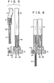
- the first and second armour tubes 11 and 12 are entirely separated from each other, and the respective tip ends of these tubes are connected with the connector 13.
- the connector 13 is provided with a lateral hole 22 which opens into the through hole 21.
- the lateral hole 22 contains therein a compression spring 23 and an engaging pin 24 which is urged by the spring 23 so that its tip end projects into the through hole 21.
- An annular engaging recess 14a is formed in the circumferential side face of the connector pin 14 connected with the light guide 9.
- the air feed tube 5a, water feed tube 6a, suction tube 7a, and conductor 8a inserted in the second armour tube 12 are connected with the connector 13 in the same manner as the foregoing embodiment.
- the conductor 8a is connected with a contact pin 29 which is fixed to the connector 13 so as to be projected from the frontage of the connector 13.
- the air feed tube 5a is coupled with an air feed pipe 28 which is fixed to the connector 13 so that its distal end portion is projected from the connector 13.
- the suction tube 7a is connected with a suction port 27 penetratingly fixed to the outer peripheral wall of the connector 13, and, in this embodiment, is allowed to communicate with a suction unit provided separately from the light source unit.
- the water feed tube 6a is connected with the connector 13 in the same manner as the suction tube 6a.
- the second armour tube 12 may be constructed so as to be able to be easily removed from the connector.
- the second armour tube 12 and the control section 3 may be connected by means of a coupling member 30 having an external thread on the outer peripheral surface of one end thereof mating with an internal thread formed on the mouthpiece of the second armour tube 12, and another external thread on the outer peripheral surface of the other end thereof on the port 16 of the control section, as shown in Fig. 10.
- the control section 3 and the second armour tube 12 may be connected by any other suitable means than screwing, such as e.g. press fit means, beyonet coupling means, etc.
- some other suitable insert members such as conductors, may be inserted in the first armour tube.
- Fig. 11 shows an endoscope of further embodiment in which the control section 3 is provided with a projecting section 3a.
- the projecting section 3a and control section 3 may be separately formed and connected with each other, or may be integrally formed.
- the control section 3a may be made to have a flexibility.
Landscapes
- Health & Medical Sciences (AREA)
- Life Sciences & Earth Sciences (AREA)
- Surgery (AREA)
- Optics & Photonics (AREA)
- Physics & Mathematics (AREA)
- Nuclear Medicine, Radiotherapy & Molecular Imaging (AREA)
- Medical Informatics (AREA)
- Radiology & Medical Imaging (AREA)
- Biophysics (AREA)
- Engineering & Computer Science (AREA)
- Biomedical Technology (AREA)
- Heart & Thoracic Surgery (AREA)
- Pathology (AREA)
- Molecular Biology (AREA)
- Animal Behavior & Ethology (AREA)
- General Health & Medical Sciences (AREA)
- Public Health (AREA)
- Veterinary Medicine (AREA)
- Endoscopes (AREA)
Claims (7)
Priority Applications (1)
| Application Number | Priority Date | Filing Date | Title |
|---|---|---|---|
| AT81105261T ATE11099T1 (de) | 1980-07-10 | 1981-07-07 | Endoskop. |
Applications Claiming Priority (4)
| Application Number | Priority Date | Filing Date | Title |
|---|---|---|---|
| JP94190/80 | 1980-07-10 | ||
| JP9419080A JPS5720245A (en) | 1980-07-10 | 1980-07-10 | Endoscope |
| JP13612780A JPS5720247A (en) | 1980-09-30 | 1980-09-30 | Endoscope |
| JP136127/80 | 1980-09-30 |
Publications (2)
| Publication Number | Publication Date |
|---|---|
| EP0044018A1 EP0044018A1 (de) | 1982-01-20 |
| EP0044018B1 true EP0044018B1 (de) | 1985-01-09 |
Family
ID=26435473
Family Applications (1)
| Application Number | Title | Priority Date | Filing Date |
|---|---|---|---|
| EP81105261A Expired EP0044018B1 (de) | 1980-07-10 | 1981-07-07 | Endoskop |
Country Status (3)
| Country | Link |
|---|---|
| US (1) | US4416268A (de) |
| EP (1) | EP0044018B1 (de) |
| DE (1) | DE3168137D1 (de) |
Families Citing this family (25)
| Publication number | Priority date | Publication date | Assignee | Title |
|---|---|---|---|---|
| JPS5886133A (ja) * | 1981-11-19 | 1983-05-23 | オリンパス光学工業株式会社 | 内視鏡用送液装置 |
| USD277407S (en) | 1982-03-08 | 1985-01-29 | Olympus Optical Company, Ltd. | Operating assembly of an endoscope |
| USD277405S (en) | 1982-03-08 | 1985-01-29 | Olympus Optical Company, Ltd. | Operating assembly of an endoscope |
| USD277406S (en) | 1982-03-08 | 1985-01-29 | Olympus Optical Company, Ltd. | Operating assembly of an endoscope |
| USD277408S (en) | 1982-03-18 | 1985-01-29 | Olympus Optical Company, Ltd. | Light guide for endoscope |
| USD277505S (en) | 1982-03-19 | 1985-02-05 | Olympus Optical Co., Ltd. | Endoscope |
| US4534339A (en) * | 1983-10-17 | 1985-08-13 | Warner-Lambert Technologies, Inc. | Endoscope |
| US4832444A (en) * | 1985-06-17 | 1989-05-23 | Sumitomo Electric Industries, Ltd. | Method and apparatus for transmitting light |
| DE3738633A1 (de) * | 1987-11-16 | 1989-05-24 | Wolf Gmbh Richard | Steckvorrichtung fuer endoskope |
| US5100343A (en) * | 1990-07-19 | 1992-03-31 | The Marley Company | Electrical connector for float controlled pumps |
| JP2948640B2 (ja) * | 1990-09-18 | 1999-09-13 | 旭光学工業株式会社 | 内視鏡のコネクタ装置 |
| JP3070405B2 (ja) * | 1994-08-18 | 2000-07-31 | 富士写真光機株式会社 | 内視鏡のライトガイドコネクタ |
| US6401066B1 (en) * | 1999-11-09 | 2002-06-04 | West Teleservices Holding Company | Automated third party verification system |
| US6340344B1 (en) * | 2000-07-18 | 2002-01-22 | Evergreen Medical Incorporated | Endoscope with a removable suction tube |
| US7758498B2 (en) * | 2003-03-06 | 2010-07-20 | Precision Optics Corporation | Endoscope with relief of axial loading |
| US7699773B2 (en) * | 2003-03-06 | 2010-04-20 | Precision Optics Corporation | Repairable endoscope |
| JP4461100B2 (ja) * | 2004-02-16 | 2010-05-12 | オリンパス株式会社 | 内視鏡システム |
| DE102004008458A1 (de) * | 2004-02-16 | 2005-09-01 | Karl Storz Gmbh & Co. Kg | Verfahren zum Fixieren von Glasfasern in einem Endoskop |
| CA2772341A1 (en) * | 2009-08-31 | 2011-03-03 | Bracco Diagnostics Inc. | In-line gas adaptor for endoscopic apparatus |
| US8292805B2 (en) | 2009-11-10 | 2012-10-23 | Invuity, Inc. | Illuminated suction apparatus |
| USD641470S1 (en) * | 2010-04-12 | 2011-07-12 | Hoya Corporation | Endoscope |
| DE102014204997B4 (de) * | 2014-03-18 | 2016-08-18 | Olympus Winter & Ibe Gmbh | Pumpenvorrichtung |
| JP6302863B2 (ja) * | 2015-03-31 | 2018-03-28 | 富士フイルム株式会社 | 内視鏡装置 |
| US11166621B2 (en) * | 2017-03-08 | 2021-11-09 | Sony Olympus Medical Solutions Inc. | Medical apparatus and method of manufacturing medical apparatus |
| US11823835B2 (en) * | 2021-07-06 | 2023-11-21 | Karl Storz Imaging, Inc. | Electrical device with magnetic connector |
Family Cites Families (9)
| Publication number | Priority date | Publication date | Assignee | Title |
|---|---|---|---|---|
| US3294085A (en) * | 1963-09-27 | 1966-12-27 | American Cystoscope Makers Inc | Endoscope |
| DE1791141C3 (de) * | 1967-09-21 | 1973-12-06 | Olympus Optical Co. Ltd., Tokio | Endoskop mit Zusammenfassung aus dem Steuergehause herausgeführter Lei tungen |
| US3590232A (en) * | 1968-03-27 | 1971-06-29 | Radioptics Inc | Annular illuminator for dental tools or the like |
| US3850162A (en) * | 1972-07-03 | 1974-11-26 | J Iglesias | Endoscope with continuous irrigation |
| DE2738203C2 (de) * | 1977-08-24 | 1979-10-25 | Heine Optotechnik Gmbh & Co Kg, 8036 Herrsching | Endoskop, insbesondere Rektoskop, mit entfernbarem Kopfgehäuse-Deckel mit Fenster |
| US4190041A (en) * | 1977-09-12 | 1980-02-26 | Machida Endoscope Co., Ltd. | Cleaning device for wire guide tube in an endoscope |
| JPS5568350A (en) * | 1978-11-20 | 1980-05-23 | Olympus Optical Co | Connector for endoscope |
| JPS55130640A (en) * | 1979-03-30 | 1980-10-09 | Olympus Optical Co | Endoscope |
| US4294234A (en) * | 1979-06-22 | 1981-10-13 | Olympus Optical Co., Ltd. | Endoscope |
-
1981
- 1981-06-29 US US06/278,096 patent/US4416268A/en not_active Expired - Lifetime
- 1981-07-07 DE DE8181105261T patent/DE3168137D1/de not_active Expired
- 1981-07-07 EP EP81105261A patent/EP0044018B1/de not_active Expired
Also Published As
| Publication number | Publication date |
|---|---|
| DE3168137D1 (en) | 1985-02-21 |
| EP0044018A1 (de) | 1982-01-20 |
| US4416268A (en) | 1983-11-22 |
Similar Documents
| Publication | Publication Date | Title |
|---|---|---|
| US4416268A (en) | Endoscope having two detachable armour tubes | |
| EP0046238B1 (de) | Endoskop mit Adaptereinheit | |
| EP2022389B1 (de) | Endoskop und Endoskopvorrichtung | |
| JP5149463B2 (ja) | コネクタシステム | |
| US11471031B2 (en) | Articulated tip part for an endoscope | |
| JPH0372288B2 (de) | ||
| CN111035347A (zh) | 用于内窥镜的铰接式尖端部分 | |
| CN112423646A (zh) | 内窥镜的前端部 | |
| JPS6155657B2 (de) | ||
| JPH0549594A (ja) | 電動湾曲式内視鏡装置 | |
| US4770443A (en) | Inserted part of an industrial endoscope | |
| JPH10229965A (ja) | 内視鏡 | |
| US5735794A (en) | Endoscope having external battery connected to battery casing | |
| JPH0146848B2 (de) | ||
| EP0066111A1 (de) | Kupplungsanordnung für ein Lichtquellensystem eines Endoskops | |
| JPH04317622A (ja) | 内視鏡の先端部 | |
| JPH0745059Y2 (ja) | 内視鏡におけるライトガイドケーブルのコネクター | |
| JPS5841525A (ja) | 内視鏡用光源装置 | |
| JPS6343446Y2 (de) | ||
| JPH0143686Y2 (de) | ||
| JP3151302B2 (ja) | 電子内視鏡のケーブル | |
| JP3218703B2 (ja) | 鉗子口装置 | |
| JPH0228493Y2 (de) | ||
| JPH01221717A (ja) | 内視鏡装置 | |
| JP2843367B2 (ja) | 内視鏡 |
Legal Events
| Date | Code | Title | Description |
|---|---|---|---|
| PUAI | Public reference made under article 153(3) epc to a published international application that has entered the european phase |
Free format text: ORIGINAL CODE: 0009012 |
|
| AK | Designated contracting states |
Designated state(s): AT BE CH DE FR GB IT NL SE |
|
| 17P | Request for examination filed |
Effective date: 19820204 |
|
| GRAA | (expected) grant |
Free format text: ORIGINAL CODE: 0009210 |
|
| AK | Designated contracting states |
Designated state(s): AT BE CH DE FR GB IT LI NL SE |
|
| PG25 | Lapsed in a contracting state [announced via postgrant information from national office to epo] |
Ref country code: SE Effective date: 19850109 Ref country code: NL Effective date: 19850109 Ref country code: LI Effective date: 19850109 Ref country code: IT Free format text: LAPSE BECAUSE OF FAILURE TO SUBMIT A TRANSLATION OF THE DESCRIPTION OR TO PAY THE FEE WITHIN THE PRESCRIBED TIME-LIMIT;WARNING: LAPSES OF ITALIAN PATENTS WITH EFFECTIVE DATE BEFORE 2007 MAY HAVE OCCURRED AT ANY TIME BEFORE 2007. THE CORRECT EFFECTIVE DATE MAY BE DIFFERENT FROM THE ONE RECORDED. Effective date: 19850109 Ref country code: CH Effective date: 19850109 Ref country code: BE Effective date: 19850109 Ref country code: AT Effective date: 19850109 |
|
| REF | Corresponds to: |
Ref document number: 11099 Country of ref document: AT Date of ref document: 19850115 Kind code of ref document: T |
|
| REF | Corresponds to: |
Ref document number: 3168137 Country of ref document: DE Date of ref document: 19850221 |
|
| ET | Fr: translation filed | ||
| REG | Reference to a national code |
Ref country code: CH Ref legal event code: PL |
|
| NLV1 | Nl: lapsed or annulled due to failure to fulfill the requirements of art. 29p and 29m of the patents act | ||
| PLBE | No opposition filed within time limit |
Free format text: ORIGINAL CODE: 0009261 |
|
| STAA | Information on the status of an ep patent application or granted ep patent |
Free format text: STATUS: NO OPPOSITION FILED WITHIN TIME LIMIT |
|
| 26N | No opposition filed | ||
| PGFP | Annual fee paid to national office [announced via postgrant information from national office to epo] |
Ref country code: GB Payment date: 19960628 Year of fee payment: 16 |
|
| PGFP | Annual fee paid to national office [announced via postgrant information from national office to epo] |
Ref country code: FR Payment date: 19960709 Year of fee payment: 16 |
|
| PGFP | Annual fee paid to national office [announced via postgrant information from national office to epo] |
Ref country code: DE Payment date: 19960712 Year of fee payment: 16 |
|
| PG25 | Lapsed in a contracting state [announced via postgrant information from national office to epo] |
Ref country code: GB Free format text: LAPSE BECAUSE OF NON-PAYMENT OF DUE FEES Effective date: 19970707 |
|
| GBPC | Gb: european patent ceased through non-payment of renewal fee |
Effective date: 19970707 |
|
| PG25 | Lapsed in a contracting state [announced via postgrant information from national office to epo] |
Ref country code: FR Free format text: LAPSE BECAUSE OF NON-PAYMENT OF DUE FEES Effective date: 19980331 |
|
| PG25 | Lapsed in a contracting state [announced via postgrant information from national office to epo] |
Ref country code: DE Free format text: LAPSE BECAUSE OF NON-PAYMENT OF DUE FEES Effective date: 19980401 |
|
| REG | Reference to a national code |
Ref country code: FR Ref legal event code: ST |