EP0044151A1 - Anordnung zum Aufzeichnen und/oder Lesen binärer Daten von beiden Seiten einer flexiblen Magnetplatte - Google Patents
Anordnung zum Aufzeichnen und/oder Lesen binärer Daten von beiden Seiten einer flexiblen Magnetplatte Download PDFInfo
- Publication number
- EP0044151A1 EP0044151A1 EP81302893A EP81302893A EP0044151A1 EP 0044151 A1 EP0044151 A1 EP 0044151A1 EP 81302893 A EP81302893 A EP 81302893A EP 81302893 A EP81302893 A EP 81302893A EP 0044151 A1 EP0044151 A1 EP 0044151A1
- Authority
- EP
- European Patent Office
- Prior art keywords
- disk
- head
- carriage
- plane
- arm
- Prior art date
- Legal status (The legal status is an assumption and is not a legal conclusion. Google has not performed a legal analysis and makes no representation as to the accuracy of the status listed.)
- Granted
Links
- 229920003023 plastic Polymers 0.000 claims description 8
- 239000004033 plastic Substances 0.000 claims description 8
- 239000000463 material Substances 0.000 claims description 5
- 230000035515 penetration Effects 0.000 description 4
- 230000010355 oscillation Effects 0.000 description 3
- 230000001050 lubricating effect Effects 0.000 description 2
- 239000002184 metal Substances 0.000 description 2
- 238000000465 moulding Methods 0.000 description 2
- 230000002411 adverse Effects 0.000 description 1
- 238000005452 bending Methods 0.000 description 1
- 230000000694 effects Effects 0.000 description 1
- 238000004519 manufacturing process Methods 0.000 description 1
Images


Classifications
-
- G—PHYSICS
- G11—INFORMATION STORAGE
- G11B—INFORMATION STORAGE BASED ON RELATIVE MOVEMENT BETWEEN RECORD CARRIER AND TRANSDUCER
- G11B5/00—Recording by magnetisation or demagnetisation of a record carrier; Reproducing by magnetic means; Record carriers therefor
- G11B5/48—Disposition or mounting of heads or head supports relative to record carriers ; arrangements of heads, e.g. for scanning the record carrier to increase the relative speed
- G11B5/58—Disposition or mounting of heads or head supports relative to record carriers ; arrangements of heads, e.g. for scanning the record carrier to increase the relative speed with provision for moving the head for the purpose of maintaining alignment of the head relative to the record carrier during transducing operation, e.g. to compensate for surface irregularities of the latter or for track following
-
- G—PHYSICS
- G11—INFORMATION STORAGE
- G11B—INFORMATION STORAGE BASED ON RELATIVE MOVEMENT BETWEEN RECORD CARRIER AND TRANSDUCER
- G11B21/00—Head arrangements not specific to the method of recording or reproducing
- G11B21/16—Supporting the heads; Supporting the sockets for plug-in heads
- G11B21/20—Supporting the heads; Supporting the sockets for plug-in heads while the head is in operative position but stationary or permitting minor movements to follow irregularities in surface of record carrier
Definitions
- This invention relates to a device for recording and/or reading binary data on both faces of a flexible magnetic disk, which may be contained in a cardboard or plastics sleeve.
- the magnetic disk is normally constituted by a thin plastics sheet coated on both sides with a layer of magnetisable material, and can rotate inside its sleeve by virtue of the presence of a lubricating material.
- the sleeve has a central through hole via which access can be gained to the magnetic disk from both sides in order to rotate it by drive means.
- the faces of the sleeve are provided with a pair of opposed slots disposed radially relative to the disk, through which access can be gained to the disk by means of the magnetic recording and/or reading heads.
- the sleeve Before bringing the magnetic heads into contact with the disk faces, the sleeve is urged by a presser against a fixed reference surface, in order to flatten the sleeve in a zone close to its radial slots, and thus position the disk in a nominal working plane.
- a recording and/or reading device in which two arms disposed on opposite sides of the disk are pivoted to a carriage mobile radially along the axis of the sleeve slots, and are both movable between a rest position, in which they are spaced well away from the magnetisable surfaces of the disk, and a working position in which they are in proximity to the disk.
- a magnetic head is mounted by means of a very yieldable spring at the end of each arm, and can rotate in all directions about a central support.
- the two opposing heads are kept in contact with the disk faces by means of a very small load, of about 8 grams.
- the magnetic heads are in theory free to follow every oscillation of the disk during its rotation, and can also move along an axis perpendicular to the plane of the disk, if this latter becomes disposed in a plane other than its nominal plane of rotation.
- this device Besides requiring high precision in terms of its assembly and its setting in the apparatus in which it is mounted, this device has the drawback of causing excessive wear of the disk, in particular during the stage in which the heads "land” on the magnetised surfaces, and of providing very inconstant contact between the magnetic heads and the disk, and as a consequence a signal which is of non-uniform amplitude.
- the lower magnetic head is fixed on to the carriage, and its surface which makes contact with the disk is perfectly flat in order to define a reference surface against which the disk rests with its lower face.
- the lower head is positioned on the carriage in such a manner that its flat surface is always above the nominal plane of rotation of the disk so that, during operation, the head "penetrates" into the disk, deforming it locally.
- a load of about 18 grams is applied to the upper head, which is of the type in the device described heretofore, and this tends to flatten the disk zone between the heads against the flat surface of the lower head.
- the lower head is therefore in an absolutely fixed position relative to the direction normal to the plane of the disk.
- the disk can become positioned in planes other than the nominal plane because of the sleeve tolerances, and the tolerances of the entire recording and/or reading apparatus. The consequence is that this latter device has the drawback of very variable local deformation of the disk.
- the object of the present invention is to provide a device for recording and/or reading binary data on both faces of a flexible magnetic disk, in which the head-disk contact is always ensured and constant, in order to provide a recorded and/or read signal which is uniform in amplitude, and in which the heads do not subject the disk to wear during its rotation.
- the device according to the invention is defined in claim 1 below.
- the device embodying the invention can record and/or read binary data on both faces. of a flexible magnetic disk 10 ( Figure 6) contained in a sleeve 11 which is substantially square and closed on all sides.
- the magnetic disk 10 known commercially as a "floppy disk” is constituted by a thin plastics sheet having a thickness of about 0.08 mm coated on both faces with a layer of magnetisable material a few microns thick, and can rotate in the sleeve 11 without damage, due to the presence of a lubricating material.
- a spindle of known type, not shown on the drawings, can engage with the disk 10 through a central hole-12 in the sleeve 11, and rotate it.
- the sleeve 11 is also provided with a pair of opposed slots 14 ( Figures 3 and 7) disposed radially to the disk 10. In the zone comprising the slots 14, the thickness of the sleeve 11 is about 1 millimetre.
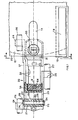
- the apparatus which handle such flexible magnetic disks are conventionally provided with a fixed horizontal reference surface 16 ( Figures 1 and 3), on which the sleeve 11 rests.
- the sleeve is pressed down by a plate 18 with a force P of about 80 grams.
- the effect of the force P is that the sleeve 11 and disk 10 tend to become flattened and become disposed in a nominal working plane n, (Fig 5).
- the nominal theoretical plane n in which the lower face of the disk becomes disposed is 0.45 mm + 150 ⁇ m higher than the plane of the reference surface 16.
- the device embodying the invention ( Figures 1 and 2) comprises a plastics carriage 20 with a rear body 21 (to the left of the figures) and two substantially parallel lateral arms 22 and 23.
- the carriage 20 is slidable on two cylindrical guides 26 and 27 along an axis x, radial with respect to the disk 10, by means of two bushes 24 integral with and projecting laterally from the arm 22, and a pair of guide lugs 25 integral with and projecting laterally from the arm 23.
- the carriage 20 is driven along the guides 26 and 27 in known manner, for example by means of an electric motor.
- These springs 32 are about 20 mm long, and have a substantially linear elastic characteristic with a very low coefficient of elasticity, for example 0.015 mm/g. The assembly of the springs 32 will also be described in detail hereinafter.
- An upper arm 36 is pivoted, by means of two lugs 35 thereof, on a pin 33 in the rear body 21, and its front end carries a further magnetic head 37 opposing the head 30.
- the pin 33 is of metal, and has its central cylindrical part 28 housed in a bore 29 in the rear body 21.
- the two ends of the pin 33 are conical, and each is housed in a corresponding bore 34 of the lugs 35, which have a diameter smaller than the central part 28 of the pin 33.
- the lugs 35 are of metal, and are resiliently urged towards the body 21 of the carriage 20 so as to totally take up the slack between their bores 34 and the conical ends of the pin 33.
- a spring 38 of known type resiliently connects the head 37 to two projections 39 and 40 of the arm 36, in such a manner as to enable the head to rotate in any direction about a central support 41.
- the arm 36 is also provided with a lateral lug 42, by means of which a control electromagnet, of known type and not shown on the drawings, can selectively move the upper magnetic head 37 away from the disk 10, or allow it to go towards the disk 10.
- a control electromagnet of known type and not shown on the drawings
- the lower head 30 ( Figure 5) is of the type known as a "button head", with a central surface 50 which is normally in contact with the lower face of the disk, and which is connected to the base by means of an annular connection portion 51 having a radius R of about 50 mm.
- the surface 50 instead of being flat or hemispherical, as in the case of known heads, is cylindrical and has its generating lines parallel to the axis x.
- the radius of curvature R 2 of the surface 50 exceeds 100 mm and may be about 150mm.
- the leaf springs 32 are assembled on the carriage 20 as follows. Initially, the block 31 ( Figure 4) is connected to the rear body 21 of the carriage 20 by means of four struts 52 parallel to the axis x, formed during the moulding of the carriage 20. In addition, during moulding, the body 21 is so profiled that it comprises a first centering pin 54 ( Figure 2), while the block 31 comprises a second centering pin 55.
- the leaf springs 32 are embedded separately at their ends in two plastics blocks 56 and 57 of substantially parallelepiped shape, each comprising a central bore, 58 and 59 respectively.
- the two blocks 56 and 57 are then cemented one to the body 21 of the carriage 20 and the other to the front block 31.
- the pins 54 and 55 position the springs 32 accurately relative to the body 21 and block 31.
- the lower magnetic head 30 When in the first position, and without the disk inserted into the apparatus, the lower magnetic head 30 is normally positioned such that the apex of its surface 50 is at a higher level than the theoretical nominal plane n ( Figure 5). This level is about 1 millimetre, but can vary between 0.3 mm and 2 mm, above the plane n and this is one of the characteristics of the device embodying the invention.
- the lower head 30 comes into contact with the lower face of the disk 10.
- the weight of the disk 10 and of the sleeve 11 cause the lower head 30 to fall by about 0.1 mm.
- the disk 10 (Fig 1) is then rotated clockwise relative to the sleeve 11, which remains at rest.
- the carriage 20 is moved along the axis x radially with respect to the disk 10 until the head 30 is positioned on the required section on which binary data is to be recorded and/or read.
- the presser 18 is lowered, and the case 11 is pressed against the fixed horizontal reference surface 16.
- the disk 10 becomes flattened, to cause the lower head 30 to fall further by about another 0.1 mm. This value is related only to the pressure of the disk 10 on the head 30, and not to the mechanical dimensions of the sleeve, because of which any type of commercially known sleeve is always accepted by the device, without adversely influencing the head-disk position.
- the level at which the heads 30 and 37 become positioned relative to the nominal working plane n of the disk 10 is exclusively a function of the forces F and R, and of the component of the force P in the zone of the . heads, and is not strictly related to the mechanical dimensions of the apparatus and sleeve 11 relative to the carriage 20.
- the penetration of the lower head 30 into the disk 10 varies according to the position in which the head 30 is located relative to the nominal plane n before inserting the disk 10 into the apparatus.
- the penetration varies under certain operating conditions between zero and 1.3 mm.
- this penetration also varies during operation, in that the unit formed by the two heads 30 and 37 pressed together by a force F of about 15 grams is resiliently connected to the fixed body 21 of the carriage 20, and this unit is therefore able to follow the oscillations of the disk 10 in a vertical direction.
- a further characteristic of the device embodying the invention is that because of the parallelogram connection provided by the springs 32, the lower head 30 can move vertically, while always keeping the generating lines of the surface 50 parallel to the axis x. It is apparent that because of the elasticity of the leaf springs 32, small torsional movements of the lower head 30 are possible, but those are of an order of magnitude less than the movements due to the bending of the springs 32.
Landscapes
- Supporting Of Heads In Record-Carrier Devices (AREA)
- Moving Of Heads (AREA)
Applications Claiming Priority (2)
| Application Number | Priority Date | Filing Date | Title |
|---|---|---|---|
| IT68110/80A IT1128485B (it) | 1980-07-14 | 1980-07-14 | Dispositivo per registrare e o leggere informazioni binarie su entrambe le facce di un disco magnetico flessibile |
| IT6811080 | 1980-07-14 |
Publications (2)
| Publication Number | Publication Date |
|---|---|
| EP0044151A1 true EP0044151A1 (de) | 1982-01-20 |
| EP0044151B1 EP0044151B1 (de) | 1984-09-26 |
Family
ID=11307916
Family Applications (1)
| Application Number | Title | Priority Date | Filing Date |
|---|---|---|---|
| EP81302893A Expired EP0044151B1 (de) | 1980-07-14 | 1981-06-26 | Anordnung zum Aufzeichnen und/oder Lesen binärer Daten von beiden Seiten einer flexiblen Magnetplatte |
Country Status (6)
| Country | Link |
|---|---|
| US (1) | US4433352A (de) |
| EP (1) | EP0044151B1 (de) |
| JP (1) | JPS5744258A (de) |
| BR (1) | BR8104468A (de) |
| DE (1) | DE3166314D1 (de) |
| IT (1) | IT1128485B (de) |
Cited By (3)
| Publication number | Priority date | Publication date | Assignee | Title |
|---|---|---|---|---|
| EP0087096A1 (de) * | 1982-02-19 | 1983-08-31 | BASF Aktiengesellschaft | Kopfarm-Lagervorrichtung für mindestens einen Abtastkopf in Aufzeichnungs- und Wiedergabegeräten für schiebenförmige Aufzeichnungsträger |
| EP0101616A3 (en) * | 1982-08-23 | 1984-09-05 | Mitsubishi Denki Kabushiki Kaisha | Magnetic head shifting means for flexible disk memory system |
| GB2180983A (en) * | 1985-09-21 | 1987-04-08 | Citizen Watch Co Ltd | Double-head supporting mechanism for a magnetic disk drive |
Families Citing this family (8)
| Publication number | Priority date | Publication date | Assignee | Title |
|---|---|---|---|---|
| JPS60113360A (ja) * | 1983-11-24 | 1985-06-19 | Mitsubishi Electric Corp | 磁気デイスク装置 |
| JPS6150253A (ja) * | 1984-08-18 | 1986-03-12 | Citizen Watch Co Ltd | フロツピデイスクドライブのヘツド支持機構 |
| JPH035024Y2 (de) * | 1984-11-16 | 1991-02-08 | ||
| US4811143A (en) * | 1986-03-31 | 1989-03-07 | Kabushiki Kaisha Toshiba | Head supporting mechanism for maintaining close operative relationship between magnetic heads and a flexible disk |
| US4855851A (en) * | 1988-03-02 | 1989-08-08 | Magnetic Peripherals Inc. | Head suspension for magnetic recording |
| JP2570058B2 (ja) * | 1992-05-27 | 1997-01-08 | ティアック株式会社 | キャリッジ機構 |
| JP2702472B2 (ja) * | 1996-03-25 | 1998-01-21 | 株式会社日立製作所 | 磁気ディスク駆動装置 |
| JP2001160251A (ja) * | 1999-12-01 | 2001-06-12 | Matsushita Electric Ind Co Ltd | フロッピーディスク装置 |
Citations (4)
| Publication number | Priority date | Publication date | Assignee | Title |
|---|---|---|---|---|
| US3787644A (en) * | 1972-07-12 | 1974-01-22 | Digital Equipment Corp | Magnetic head adjustment assembly |
| US3973274A (en) * | 1974-09-30 | 1976-08-03 | Sycor, Inc. | Method and apparatus for mounting and positioning magnetic recording heads |
| US4028734A (en) * | 1975-05-19 | 1977-06-07 | American Magnetics Corporation | Plural magnetic head assembly with independently supporting structure |
| DE2948147A1 (de) * | 1978-12-01 | 1980-06-19 | Hitachi Ltd | Magnetkopf zum aufzeichnen und wiedergeben von signalen |
Family Cites Families (3)
| Publication number | Priority date | Publication date | Assignee | Title |
|---|---|---|---|---|
| US4306258A (en) * | 1978-06-26 | 1981-12-15 | Mitsubishi Denki Kabushiki Kaisha | Magnetic head supporting mechanism of double side type flexible disc drive apparatus |
| US4247877A (en) * | 1979-08-06 | 1981-01-27 | Siemens Corporation | Head loading carriage assembly for a floppy disk drive |
| US4309732A (en) * | 1979-10-05 | 1982-01-05 | Nortronics Company, Inc. | Transducer supporting assembly for double sided floppy disk |
-
1980
- 1980-07-14 IT IT68110/80A patent/IT1128485B/it active
-
1981
- 1981-06-26 EP EP81302893A patent/EP0044151B1/de not_active Expired
- 1981-06-26 DE DE8181302893T patent/DE3166314D1/de not_active Expired
- 1981-07-01 US US06/279,625 patent/US4433352A/en not_active Expired - Fee Related
- 1981-07-13 BR BR8104468A patent/BR8104468A/pt unknown
- 1981-07-14 JP JP56109928A patent/JPS5744258A/ja active Pending
Patent Citations (5)
| Publication number | Priority date | Publication date | Assignee | Title |
|---|---|---|---|---|
| US3787644A (en) * | 1972-07-12 | 1974-01-22 | Digital Equipment Corp | Magnetic head adjustment assembly |
| DE2335050A1 (de) * | 1972-07-12 | 1974-01-31 | Digital Equipment Corp | Magnetkopfhalterung |
| US3973274A (en) * | 1974-09-30 | 1976-08-03 | Sycor, Inc. | Method and apparatus for mounting and positioning magnetic recording heads |
| US4028734A (en) * | 1975-05-19 | 1977-06-07 | American Magnetics Corporation | Plural magnetic head assembly with independently supporting structure |
| DE2948147A1 (de) * | 1978-12-01 | 1980-06-19 | Hitachi Ltd | Magnetkopf zum aufzeichnen und wiedergeben von signalen |
Non-Patent Citations (1)
| Title |
|---|
| IBM Technical Disclosure Bulletin, Vol. 19, No. 5, October 1976, pages 1808-1809 New York, U.S.A. H.J. MUELLER: "Magnetic Stripe Reader/Writer with Improved Head Suspension" * whole document * * |
Cited By (6)
| Publication number | Priority date | Publication date | Assignee | Title |
|---|---|---|---|---|
| EP0087096A1 (de) * | 1982-02-19 | 1983-08-31 | BASF Aktiengesellschaft | Kopfarm-Lagervorrichtung für mindestens einen Abtastkopf in Aufzeichnungs- und Wiedergabegeräten für schiebenförmige Aufzeichnungsträger |
| US4578726A (en) * | 1982-02-19 | 1986-03-25 | Basf Aktiengesellschaft | Head arm mounting device for one or more scanning heads in recording playback apparatus for disk records |
| EP0101616A3 (en) * | 1982-08-23 | 1984-09-05 | Mitsubishi Denki Kabushiki Kaisha | Magnetic head shifting means for flexible disk memory system |
| US4630155A (en) * | 1982-08-23 | 1986-12-16 | Mitsubishi Denki Kabushiki Kaisha | Magnetic head shifting means for flexible disk memory system |
| GB2180983A (en) * | 1985-09-21 | 1987-04-08 | Citizen Watch Co Ltd | Double-head supporting mechanism for a magnetic disk drive |
| GB2180983B (en) * | 1985-09-21 | 1989-10-18 | Citizen Watch Co Ltd | Double-head supporting mechanism for a magnetic disk drive |
Also Published As
| Publication number | Publication date |
|---|---|
| IT1128485B (it) | 1986-05-28 |
| JPS5744258A (en) | 1982-03-12 |
| DE3166314D1 (en) | 1984-10-31 |
| EP0044151B1 (de) | 1984-09-26 |
| BR8104468A (pt) | 1982-03-30 |
| IT8068110A0 (it) | 1980-07-14 |
| US4433352A (en) | 1984-02-21 |
Similar Documents
| Publication | Publication Date | Title |
|---|---|---|
| US5321568A (en) | Head suspension assembly with improved pitch and roll characteristics | |
| US4151573A (en) | Magnetic recording device for double sided media | |
| EP0044151B1 (de) | Anordnung zum Aufzeichnen und/oder Lesen binärer Daten von beiden Seiten einer flexiblen Magnetplatte | |
| KR0177140B1 (ko) | 테이프 카세트 | |
| US4528607A (en) | Magnetic record/playback head positioning apparatus | |
| DE69214177T2 (de) | Informationsverarbeitungsgerät | |
| US4085428A (en) | Apparatus for recording and reproducing information with respect to a flexible recording medium | |
| EP0097221B1 (de) | Harte Kassette für flexible Platte | |
| EP0779624A1 (de) | Verfahren un Vorrichtung zum Läppen von Gleitkörpern | |
| US4510591A (en) | Slot type disc recorder and/or player apparatus | |
| EP0259952A1 (de) | Magnetkopfhalterungssystem für eine Doppelkopfplatteneinheit | |
| JPS6222196B2 (de) | ||
| WO1982001439A1 (en) | Magnetic transducer suspension device | |
| US5659448A (en) | Magnetic head supporting mechanism including a slider fixed to a slider spacer by a fixing area smaller than a contact area | |
| EP0019083A1 (de) | Magnetkopf-Befestigungsvorrichtung | |
| CA1284840C (en) | Magnetic recording and reproducing device | |
| US4791501A (en) | Magnetic head support apparatus for a two-sided floppy disk drive | |
| US4811144A (en) | Magnetic recording head motion translation apparatus for head/media evaluation systems | |
| US4320426A (en) | Head assembly for recording on magnetic disc | |
| US4387409A (en) | Magnetic head arm mounting apparatus | |
| EP0192938A2 (de) | Schreib-Lesekopfanordnung für flexible Magnetplatten | |
| US6317295B1 (en) | Adjustment apparatus for magnetic head device | |
| GB2060979A (en) | Magnetic disc data storage apparatus | |
| EP0143443A2 (de) | Magnetplattenkopfgerät | |
| EP0210400A1 (de) | Träger für Magnetkopf für eine flexible Platte mit zwei Aufzeichnungsarten |
Legal Events
| Date | Code | Title | Description |
|---|---|---|---|
| PUAI | Public reference made under article 153(3) epc to a published international application that has entered the european phase |
Free format text: ORIGINAL CODE: 0009012 |
|
| AK | Designated contracting states |
Designated state(s): DE FR GB |
|
| 17P | Request for examination filed |
Effective date: 19820712 |
|
| GRAA | (expected) grant |
Free format text: ORIGINAL CODE: 0009210 |
|
| AK | Designated contracting states |
Designated state(s): DE FR GB |
|
| REF | Corresponds to: |
Ref document number: 3166314 Country of ref document: DE Date of ref document: 19841031 |
|
| ET | Fr: translation filed | ||
| PLBE | No opposition filed within time limit |
Free format text: ORIGINAL CODE: 0009261 |
|
| STAA | Information on the status of an ep patent application or granted ep patent |
Free format text: STATUS: NO OPPOSITION FILED WITHIN TIME LIMIT |
|
| 26N | No opposition filed | ||
| PGFP | Annual fee paid to national office [announced via postgrant information from national office to epo] |
Ref country code: GB Payment date: 19910614 Year of fee payment: 11 |
|
| PGFP | Annual fee paid to national office [announced via postgrant information from national office to epo] |
Ref country code: FR Payment date: 19910619 Year of fee payment: 11 |
|
| PGFP | Annual fee paid to national office [announced via postgrant information from national office to epo] |
Ref country code: DE Payment date: 19910723 Year of fee payment: 11 |
|
| PG25 | Lapsed in a contracting state [announced via postgrant information from national office to epo] |
Ref country code: GB Effective date: 19920626 |
|
| GBPC | Gb: european patent ceased through non-payment of renewal fee |
Effective date: 19920626 |
|
| PG25 | Lapsed in a contracting state [announced via postgrant information from national office to epo] |
Ref country code: FR Effective date: 19930226 |
|
| PG25 | Lapsed in a contracting state [announced via postgrant information from national office to epo] |
Ref country code: DE Effective date: 19930302 |
|
| REG | Reference to a national code |
Ref country code: FR Ref legal event code: ST |