EP0044469A1 - Crampon pour l'attache de tubes de chauffage au plancher - Google Patents
Crampon pour l'attache de tubes de chauffage au plancher Download PDFInfo
- Publication number
- EP0044469A1 EP0044469A1 EP81105319A EP81105319A EP0044469A1 EP 0044469 A1 EP0044469 A1 EP 0044469A1 EP 81105319 A EP81105319 A EP 81105319A EP 81105319 A EP81105319 A EP 81105319A EP 0044469 A1 EP0044469 A1 EP 0044469A1
- Authority
- EP
- European Patent Office
- Prior art keywords
- base part
- incisions
- extensions
- projections
- wire
- Prior art date
- Legal status (The legal status is an assumption and is not a legal conclusion. Google has not performed a legal analysis and makes no representation as to the accuracy of the status listed.)
- Withdrawn
Links
Images
Classifications
-
- F—MECHANICAL ENGINEERING; LIGHTING; HEATING; WEAPONS; BLASTING
- F24—HEATING; RANGES; VENTILATING
- F24D—DOMESTIC- OR SPACE-HEATING SYSTEMS, e.g. CENTRAL HEATING SYSTEMS; DOMESTIC HOT-WATER SUPPLY SYSTEMS; ELEMENTS OR COMPONENTS THEREFOR
- F24D3/00—Hot-water central heating systems
- F24D3/12—Tube and panel arrangements for ceiling, wall, or underfloor heating
- F24D3/14—Tube and panel arrangements for ceiling, wall, or underfloor heating incorporated in a ceiling, wall or floor
- F24D3/141—Tube mountings specially adapted therefor
- F24D3/144—Clips for fastening heating tubes on a reinforcement net or mesh, e.g. mesh for concrete reinforcement
-
- F—MECHANICAL ENGINEERING; LIGHTING; HEATING; WEAPONS; BLASTING
- F16—ENGINEERING ELEMENTS AND UNITS; GENERAL MEASURES FOR PRODUCING AND MAINTAINING EFFECTIVE FUNCTIONING OF MACHINES OR INSTALLATIONS; THERMAL INSULATION IN GENERAL
- F16B—DEVICES FOR FASTENING OR SECURING CONSTRUCTIONAL ELEMENTS OR MACHINE PARTS TOGETHER, e.g. NAILS, BOLTS, CIRCLIPS, CLAMPS, CLIPS OR WEDGES; JOINTS OR JOINTING
- F16B7/00—Connections of rods or tubes, e.g. of non-circular section, mutually, including resilient connections
- F16B7/04—Clamping or clipping connections
-
- F—MECHANICAL ENGINEERING; LIGHTING; HEATING; WEAPONS; BLASTING
- F24—HEATING; RANGES; VENTILATING
- F24D—DOMESTIC- OR SPACE-HEATING SYSTEMS, e.g. CENTRAL HEATING SYSTEMS; DOMESTIC HOT-WATER SUPPLY SYSTEMS; ELEMENTS OR COMPONENTS THEREFOR
- F24D3/00—Hot-water central heating systems
- F24D3/12—Tube and panel arrangements for ceiling, wall, or underfloor heating
- F24D3/14—Tube and panel arrangements for ceiling, wall, or underfloor heating incorporated in a ceiling, wall or floor
- F24D3/141—Tube mountings specially adapted therefor
-
- Y—GENERAL TAGGING OF NEW TECHNOLOGICAL DEVELOPMENTS; GENERAL TAGGING OF CROSS-SECTIONAL TECHNOLOGIES SPANNING OVER SEVERAL SECTIONS OF THE IPC; TECHNICAL SUBJECTS COVERED BY FORMER USPC CROSS-REFERENCE ART COLLECTIONS [XRACs] AND DIGESTS
- Y02—TECHNOLOGIES OR APPLICATIONS FOR MITIGATION OR ADAPTATION AGAINST CLIMATE CHANGE
- Y02B—CLIMATE CHANGE MITIGATION TECHNOLOGIES RELATED TO BUILDINGS, e.g. HOUSING, HOUSE APPLIANCES OR RELATED END-USER APPLICATIONS
- Y02B30/00—Energy efficient heating, ventilation or air conditioning [HVAC]
Definitions
- the invention relates to a clamp for fastening floor heating pipes to a holding strip, consisting of a base part, a holding part for the pipes provided on the top thereof, which has holding projections extending therefrom, and a pair of clamping projections projecting downward from the base part Clamping on the retaining strip, wherein incisions are provided for receiving wires of a mild steel mesh.
- underfloor heating pipes can be attached to holding strips such as Band iron or can be attached to the wires of a steel mesh.
- this prior art clip has several disadvantages. If band irons are intended to hold the clamps and the heating pipes in place, the heating pipes can only be attached at a predetermined angle relative to the band irons if you do not want to provide different clamps for different angles, which of course means greater storage, greater costs and longer working hours Finding the right parentheses would mean. If e.g. a type of clamps is provided with which the heating pipes can be arranged perpendicular to the band irons, so if a parallel arrangement is also desired, a second set of corresponding clamps would have to be provided.
- Another disadvantage of the known clip is that it has to be attached to the structural steel mesh from below. On the one hand, this means the cumbersome work of first lifting the steel mesh, which is made even more difficult by the fact that the worker stands on this steel mesh. So he has to lift part of his weight, so to speak. In addition, there is a risk that when the clips are pushed in, the insulating cover underneath, such as, for. B. bitumen p appe or polyethylene film is damaged.
- the object of the invention is to provide an improved clip of the type mentioned, which is easier to attach and more versatile to use.
- the solution according to the invention is that four holding projections arranged with cross-shaped gaps are provided, that the incisions for receiving wires of the structural steel fabric are provided on the underside of the base part in the clamping projections, and that each of these two incisions has two extensions arranged one above the other.
- the clips can be attached to the wires of the structural steel mesh from above.
- the incisions have extensions that correspond to the cross-section of the wire, so that the clips hold the wire or the wire the clip very well on these extensions.
- the clip will have a certain elasticity so that after being pushed on the wires snap when they reach the extensions.
- Two extensions arranged one above the other are provided, which is important if the clip is to be fastened at crossing points of the structural steel mesh. If the wire over which the incisions are pushed is the upper one at this crossing point, the clamp can be pressed down so far that the wire snaps into the upper extension. However, if the incisions are to be pushed over the lower wire, the clip is pushed over the wire up to the lower extension. In this way, there is still space between the lower wire and a lower surface of the clamp for receiving the upper wire at the crossing point.
- the extensions can be circular cutouts. This shape is particularly advantageously adapted to the usual shape of structural steel wires which have a substantially circular cross section.
- each incision can be immediately adjacent to one another.
- the distance between the centers of the extensions corresponds approximately to the diameter the extension and thus the wire diameter.
- a shift from the lower extension to the upper extension therefore corresponds to the thickness of the wire.
- the lower surface of the base part can, apart from the clamping projections, be designed to be flat. It will have a certain minimum thickness to achieve appropriate stability.
- the lower surface of the base part, against which the wire can rest forms the groove base of two grooves running in a cross shape in the direction of the incisions or perpendicularly thereto on the underside of the base part. In this way it is achieved that the base part is weakened on two perpendicular lines so that it can be bent more easily there. This makes it easier to slide the clip over the steel mesh. The incisions open more easily because the entire base part is deformed accordingly.
- the remaining thickness of the base part should be approximately 2.5 mm in order to achieve a favorable bending behavior in the area of the grooves.
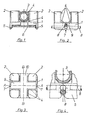
- the clip according to the invention has an essentially rectangular or square plate-shaped base part 1, from which four holding projections 2 extend upwards at the corners. Between every two adjacent retaining projections there is an equally large space between which a heating pipe 3 can be held. The heating pipe can be held in two positions in which its axis has the direction AA or BB in Fig. 3. You can do it still locking projections 4 may be provided on the holding projections 2, with which the tube between the holding projections is held better. Under the base there are two clamping projections 5 with correspondingly hook-shaped lower edges on two opposite longitudinal sides of the base part, which can be pushed over a retaining bar 6 so that the clip engages thereon. In the middle of the clamping projections 5, notches 7 are provided with two extensions, which have approximately the shape and cross-sectional area of structural steel wires 8.
- the upper extension holds the upper wire which penetrates into a groove 9 running centrally in the underside of the base part 1.
- the upper wire of the structural steel fabric, which is not held by the incision 7 is in the groove 10 perpendicular thereto, while the lower wire of the structural steel fabric is held by the incisions 7 with the lower extension.
- the grooves 9 and 10 and the resulting weakening of the base part in these areas result in increased flexibility of the base part, for example, about the lines A-A and B-B in FIG. 3. This flexibility makes it easier to snap the clip onto a steel strip or a mild steel wire. In addition, due to this flexibility, the tube can be inserted more easily into the clamp.
Landscapes
- Engineering & Computer Science (AREA)
- General Engineering & Computer Science (AREA)
- Mechanical Engineering (AREA)
- Physics & Mathematics (AREA)
- Thermal Sciences (AREA)
- Chemical & Material Sciences (AREA)
- Combustion & Propulsion (AREA)
- Supports For Pipes And Cables (AREA)
- Clamps And Clips (AREA)
Applications Claiming Priority (2)
| Application Number | Priority Date | Filing Date | Title |
|---|---|---|---|
| DE8019598U | 1980-07-22 | ||
| DE8019598U DE8019598U1 (de) | 1980-07-22 | 1980-07-22 | Klammer zum Befestigen von Fußboden-Heizungsrohren |
Publications (1)
| Publication Number | Publication Date |
|---|---|
| EP0044469A1 true EP0044469A1 (fr) | 1982-01-27 |
Family
ID=6717405
Family Applications (1)
| Application Number | Title | Priority Date | Filing Date |
|---|---|---|---|
| EP81105319A Withdrawn EP0044469A1 (fr) | 1980-07-22 | 1981-07-09 | Crampon pour l'attache de tubes de chauffage au plancher |
Country Status (3)
| Country | Link |
|---|---|
| EP (1) | EP0044469A1 (fr) |
| DE (1) | DE8019598U1 (fr) |
| DK (1) | DK325081A (fr) |
Cited By (16)
| Publication number | Priority date | Publication date | Assignee | Title |
|---|---|---|---|---|
| AT380734B (de) * | 1984-06-05 | 1986-06-25 | Kramer Karl | Schelle zur befestigung von rohren einer fussbodenheizung |
| DE9403449U1 (de) * | 1994-03-01 | 1994-04-28 | E. Missel Gmbh & Co, 70374 Stuttgart | Befestigungsschelle |
| EP1719954A1 (fr) * | 2005-05-06 | 2006-11-08 | REHAU AG + Co | Rail de fixation en polymère pour recevoir des conduits conduisant du fluide |
| DE102009023178A1 (de) * | 2009-05-29 | 2010-12-02 | Rehau Ag + Co. | Befestigungssystem zur Fixierung von Kabeln oder Rohren einer Fußbodenheizung auf Stahlgittermatten |
| CN102852220A (zh) * | 2011-06-28 | 2013-01-02 | 天津万联管道工程有限公司 | 预制格栅井 |
| WO2013058656A1 (fr) * | 2011-10-21 | 2013-04-25 | Michiels Management B.V. | Collier de tuyau |
| US10408469B2 (en) | 2014-08-18 | 2019-09-10 | Progress Profiles Spa | Method and apparatus for positioning heating elements |
| US10502434B2 (en) | 2016-04-01 | 2019-12-10 | Progress Profiles S.P.A. | Support for radiant covering and floor heating elements |
| CN111664492A (zh) * | 2020-07-14 | 2020-09-15 | 俞启鸿 | 一种换热站供暖管网 |
| US10859274B2 (en) | 2016-04-01 | 2020-12-08 | Progress Profiles S.P.A. | Support for radiant covering and floor heating elements |
| US11041638B2 (en) | 2009-08-28 | 2021-06-22 | Progress Profiles Spa | Method and apparatus for positioning heating elements |
| USD1036242S1 (en) | 2020-04-22 | 2024-07-23 | Progress Profiles S.P.A. | Floor underlayment |
| USD1036243S1 (en) | 2020-10-09 | 2024-07-23 | Progress Profiles S.P.A. | Floor underlayment |
| USD1036979S1 (en) | 2020-04-06 | 2024-07-30 | Progress Profiles S.P.A. | Floor underlayment |
| CN119826216A (zh) * | 2025-03-19 | 2025-04-15 | 中建八局天津建设工程有限公司 | 一种结构层地板辐射采暖管道的安装夹具及其安装方法 |
| USD1101979S1 (en) | 2023-02-07 | 2025-11-11 | Progress Profiles S.P.A. | Floor underlayment |
Families Citing this family (2)
| Publication number | Priority date | Publication date | Assignee | Title |
|---|---|---|---|---|
| DE3032958C2 (de) * | 1980-09-02 | 1984-12-20 | Ta Rokal GmbH, 4330 Mülheim | Abstandshalter für Heizrohre |
| CH665667A5 (de) * | 1984-03-06 | 1988-05-31 | Manfred Fennesz | Isolierplattenanordnung. |
Citations (1)
| Publication number | Priority date | Publication date | Assignee | Title |
|---|---|---|---|---|
| CH595596A5 (en) * | 1975-09-24 | 1978-02-15 | Zeigmeister H Nordrohr Kunstst | Bracket for holding floor heating tubes |
-
1980
- 1980-07-22 DE DE8019598U patent/DE8019598U1/de not_active Expired
-
1981
- 1981-07-09 EP EP81105319A patent/EP0044469A1/fr not_active Withdrawn
- 1981-07-21 DK DK325081A patent/DK325081A/da not_active Application Discontinuation
Patent Citations (1)
| Publication number | Priority date | Publication date | Assignee | Title |
|---|---|---|---|---|
| CH595596A5 (en) * | 1975-09-24 | 1978-02-15 | Zeigmeister H Nordrohr Kunstst | Bracket for holding floor heating tubes |
Cited By (25)
| Publication number | Priority date | Publication date | Assignee | Title |
|---|---|---|---|---|
| AT380734B (de) * | 1984-06-05 | 1986-06-25 | Kramer Karl | Schelle zur befestigung von rohren einer fussbodenheizung |
| DE9403449U1 (de) * | 1994-03-01 | 1994-04-28 | E. Missel Gmbh & Co, 70374 Stuttgart | Befestigungsschelle |
| EP1719954A1 (fr) * | 2005-05-06 | 2006-11-08 | REHAU AG + Co | Rail de fixation en polymère pour recevoir des conduits conduisant du fluide |
| DE102009023178A1 (de) * | 2009-05-29 | 2010-12-02 | Rehau Ag + Co. | Befestigungssystem zur Fixierung von Kabeln oder Rohren einer Fußbodenheizung auf Stahlgittermatten |
| US11846432B2 (en) | 2009-08-28 | 2023-12-19 | Progress Profiles Spa | Method and apparatus for positioning heating elements |
| US11041638B2 (en) | 2009-08-28 | 2021-06-22 | Progress Profiles Spa | Method and apparatus for positioning heating elements |
| CN102852220A (zh) * | 2011-06-28 | 2013-01-02 | 天津万联管道工程有限公司 | 预制格栅井 |
| WO2013058656A1 (fr) * | 2011-10-21 | 2013-04-25 | Michiels Management B.V. | Collier de tuyau |
| CN103958952A (zh) * | 2011-10-21 | 2014-07-30 | Q-科利普有限公司 | 管夹 |
| CN103958952B (zh) * | 2011-10-21 | 2016-12-07 | Q-科利普有限公司 | 管夹 |
| US9857086B2 (en) | 2011-10-21 | 2018-01-02 | Q-Clip B.V. | Pipe clamp |
| US10739016B2 (en) | 2014-08-18 | 2020-08-11 | Progress Profiles Spa | Method and apparatus for positioning heating elements |
| US10408469B2 (en) | 2014-08-18 | 2019-09-10 | Progress Profiles Spa | Method and apparatus for positioning heating elements |
| US10712020B2 (en) | 2014-08-18 | 2020-07-14 | Progress Profiles Spa | Method and apparatus for positioning heating elements |
| US12044417B2 (en) | 2014-08-18 | 2024-07-23 | Progress Profiles Spa | Method and apparatus for positioning heating elements |
| US12560339B2 (en) | 2016-04-01 | 2026-02-24 | Progress Profiles S.P.A. | Support for radiant covering and floor heating elements |
| US10859274B2 (en) | 2016-04-01 | 2020-12-08 | Progress Profiles S.P.A. | Support for radiant covering and floor heating elements |
| US10502434B2 (en) | 2016-04-01 | 2019-12-10 | Progress Profiles S.P.A. | Support for radiant covering and floor heating elements |
| USD1036979S1 (en) | 2020-04-06 | 2024-07-30 | Progress Profiles S.P.A. | Floor underlayment |
| USD1036242S1 (en) | 2020-04-22 | 2024-07-23 | Progress Profiles S.P.A. | Floor underlayment |
| CN111664492A (zh) * | 2020-07-14 | 2020-09-15 | 俞启鸿 | 一种换热站供暖管网 |
| USD1036243S1 (en) | 2020-10-09 | 2024-07-23 | Progress Profiles S.P.A. | Floor underlayment |
| USD1101979S1 (en) | 2023-02-07 | 2025-11-11 | Progress Profiles S.P.A. | Floor underlayment |
| CN119826216B (zh) * | 2025-03-19 | 2025-08-05 | 中建八局天津建设工程有限公司 | 一种结构层地板辐射采暖管道的安装夹具及其安装方法 |
| CN119826216A (zh) * | 2025-03-19 | 2025-04-15 | 中建八局天津建设工程有限公司 | 一种结构层地板辐射采暖管道的安装夹具及其安装方法 |
Also Published As
| Publication number | Publication date |
|---|---|
| DE8019598U1 (de) | 1980-10-16 |
| DK325081A (da) | 1982-01-23 |
Similar Documents
| Publication | Publication Date | Title |
|---|---|---|
| EP0044469A1 (fr) | Crampon pour l'attache de tubes de chauffage au plancher | |
| DE19815047A1 (de) | Anordnung zur schraubenlosen Verbindung von Gitterkabelbahnen | |
| DE3224819A1 (de) | Aufhaengung fuer deckenplatten | |
| EP1118730B1 (fr) | Espaceur de renforcement positionnant des barres d'armature vis à vis d'un coffrage pour constructions de béton | |
| DE4416722A1 (de) | Schutzzaun zur Absicherung von Gefahrzonen | |
| DE2412381C3 (de) | Befestigungsanordnung für Begrenzungstafeln in Form eines Gitters | |
| DE2005611A1 (de) | Lösbare Verbindung zweier Profilstäbe | |
| DE2510946C2 (de) | Kreuzverbindungsstueck fuer ein traggerippe einer unterdecke | |
| AT396379B (de) | Dacheindeckung aus nebeneinanderliegend angeordneten blechtafeln | |
| DE2716289C3 (de) | Führungsschiene zum Anbringen von Schubfächern an Drahtgitterwänden | |
| DE7530180U (de) | Klammer zum befestigen von fussboden- heizungrohren an einer halteleiste | |
| AT264178B (de) | Eggenbalken | |
| DE2607461C3 (de) | Versteifungsleiste für Deckenplatten | |
| CH665016A5 (de) | Trockengestell zur aufnahme zu trocknender keramischer teile, insbesondere dach- und firstziegel. | |
| DE3785971T2 (de) | Mauerverbinder. | |
| DE2843457C2 (de) | Wandbekleidung | |
| DE2554262C2 (de) | Kreuzverbinder | |
| EP0465684A1 (fr) | Dispositif de fixation de suspentes ou semblables aux profilés supports | |
| DE2405209A1 (de) | Verstellbarer distanzhalter fuer betonarmierungen | |
| CH652165A5 (de) | Insbesondere fuer garagentore bestimmte zarge mit befestigungs-vorrichtung. | |
| CH686631A5 (de) | Unterdeckenkonstruktion. | |
| CH658092A5 (de) | Bausatz zum erstellen einer abhaengbaren rasterdecke. | |
| DE7822351U1 (de) | Klammer zum befestigen von fussboden- heizungsrohren an einer halteleiste | |
| DE7720666U1 (de) | Halteschelle fuer rohre, kabel u.dgl. | |
| DE2201677C2 (de) | Klammer zum Befestigen einer Lichtkup pel auf einem Aufsatzkranz |
Legal Events
| Date | Code | Title | Description |
|---|---|---|---|
| PUAI | Public reference made under article 153(3) epc to a published international application that has entered the european phase |
Free format text: ORIGINAL CODE: 0009012 |
|
| AK | Designated contracting states |
Designated state(s): AT BE CH DE FR LU |
|
| STAA | Information on the status of an ep patent application or granted ep patent |
Free format text: STATUS: THE APPLICATION IS DEEMED TO BE WITHDRAWN |
|
| 18D | Application deemed to be withdrawn |
Effective date: 19830102 |
|
| RIN1 | Information on inventor provided before grant (corrected) |
Inventor name: LIPPE, MANFRED |