EP0045319A1 - Wiegevorrichtung - Google Patents
Wiegevorrichtung Download PDFInfo
- Publication number
- EP0045319A1 EP0045319A1 EP81900325A EP81900325A EP0045319A1 EP 0045319 A1 EP0045319 A1 EP 0045319A1 EP 81900325 A EP81900325 A EP 81900325A EP 81900325 A EP81900325 A EP 81900325A EP 0045319 A1 EP0045319 A1 EP 0045319A1
- Authority
- EP
- European Patent Office
- Prior art keywords
- weighing
- buckets
- objects
- bucket
- weight values
- Prior art date
- Legal status (The legal status is an assumption and is not a legal conclusion. Google has not performed a legal analysis and makes no representation as to the accuracy of the status listed.)
- Granted
Links
- 238000005303 weighing Methods 0.000 title claims abstract description 72
- 238000000034 method Methods 0.000 claims 1
- 244000105017 Vicia sativa Species 0.000 description 10
- 230000007246 mechanism Effects 0.000 description 5
- 238000001514 detection method Methods 0.000 description 3
- 230000002093 peripheral effect Effects 0.000 description 2
- 230000001174 ascending effect Effects 0.000 description 1
- 238000010276 construction Methods 0.000 description 1
- 238000010586 diagram Methods 0.000 description 1
- 238000007599 discharging Methods 0.000 description 1
- 238000005259 measurement Methods 0.000 description 1
- 238000004806 packaging method and process Methods 0.000 description 1
Images


Classifications
-
- G—PHYSICS
- G01—MEASURING; TESTING
- G01G—WEIGHING
- G01G13/00—Weighing apparatus with automatic feed or discharge for weighing-out batches of material
- G01G13/16—Means for automatically discharging weigh receptacles under control of the weighing mechanism
- G01G13/22—Means for automatically discharging weigh receptacles under control of the weighing mechanism by tilting or rotating the weigh receptacle
-
- G—PHYSICS
- G01—MEASURING; TESTING
- G01G—WEIGHING
- G01G19/00—Weighing apparatus or methods adapted for special purposes not provided for in the preceding groups
- G01G19/387—Weighing apparatus or methods adapted for special purposes not provided for in the preceding groups for combinatorial weighing, i.e. selecting a combination of articles whose total weight or number is closest to a desired value
- G01G19/393—Weighing apparatus or methods adapted for special purposes not provided for in the preceding groups for combinatorial weighing, i.e. selecting a combination of articles whose total weight or number is closest to a desired value using two or more weighing units
-
- G—PHYSICS
- G01—MEASURING; TESTING
- G01G—WEIGHING
- G01G13/00—Weighing apparatus with automatic feed or discharge for weighing-out batches of material
- G01G13/003—Details; specially adapted accessories
-
- G—PHYSICS
- G01—MEASURING; TESTING
- G01G—WEIGHING
- G01G19/00—Weighing apparatus or methods adapted for special purposes not provided for in the preceding groups
- G01G19/22—Weighing apparatus or methods adapted for special purposes not provided for in the preceding groups for apportioning materials by weighing prior to mixing them
- G01G19/24—Weighing apparatus or methods adapted for special purposes not provided for in the preceding groups for apportioning materials by weighing prior to mixing them using a single weighing apparatus
- G01G19/30—Weighing apparatus or methods adapted for special purposes not provided for in the preceding groups for apportioning materials by weighing prior to mixing them using a single weighing apparatus having electrical weight-sensitive devices
Definitions
- the present invention relates to a weighing apparatus, which uses combinational analysis and a transfer systems of simple mechanisms, thereby making it possible to automatically weigh not only objects which can be automatically fed and weighed but also other objects which it has heretofore been impossible to automatically weigh because they cannot be automatically fed, the intention being to provide a preset weight value or a value nearest thereto.
- the invention provides a weighing apparatus comprising a plurality of transfer and weighing lines each consisting of a bucket conveyor having a plurality of buckets for transferring objects to be weighed, and a weighing unit for weighing the buckets with objects held therein, said apparatus being adapted to drive the bucket conveyors to successively weigh the objects held in the buckets, store a predetermined number of measured weight values of the objects for each transfer and weighing line, and compute a desired or predertermaned number of combinations of the stored weight. values to obtain a combination which provides a preset weight value or a value nearest thereto.
- not only objects which can be automatically fed and automatically weighed can be automatically weighed but also other objects which it has heretofore been impossible to automatically weigh because they cannot be automatically fed, can be automatically weighed by manually feeding them.
- a target weight or a weight nearest thereto can be obtained in a short time by electronic circuitry, while the objects which have not taken part in the optimum combination can be weighed again to be used in other combinational computations, thereby increasing the computational capacity.
- the number of weighers required is only 1/2 to 1/3 as large and the large-sized pool hopper and weighing hopper are dispensed with, so that the entire apparatus is simple.
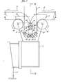
- the numeral 1 denotes a bucket conveyor having a number of buckets 5 attached to a pair of roller chains 4 meshing with driving and driven sprocket wheels 2 and 3.
- the numeral 6 denotes a drive motor for the bucket conveyor 1.
- the numeral 7 denotes a weighing unit for weighing objects fed into the buckets 5, disposed below the bucket conveyor 1.
- the numeral 8 denotes guide plates for guiding the buckets 5 to the weighing pan 9 of the weighing unit 7 so as to place them on said weighing pan, with sprocket wheels 10 and 11 of small diameter disposed on opposite sides of said weighing pan, the arrangement being such that the roller chains 4 move horizontally and then around the sprocket wheels 10 to descend along the guide plates 8 and then they ascend along the guide plates 8 until they return to their horizontal travel, as will be later described.
- the numeral 12 denotes a discharge chute disposed below the end of the bucket conveyor 1; the numeral 13 denotes a collecting conveyor; and 14 denotes a timing hopper.
- the buckets containing the objects corresponding to the combination providing the preset weight value or a value nearest thereto are tipped above the discharge chute 12 as shown in phantom line by a bucket tipping mechanism (not shown), so that the objects are discharged through the discharge chute 12 onto the collecting conveyor 13 and then into the timing hopper 14.
- the buckets 5 of the bucket conveyor 1 are attached to the roller chains 4 in the manner shown in Fig. 2.
- an attaching element 16 having an attaching shaft 16 fixed thereto is vertically fixed to an L-shaped bracket 17 fixed to the roller chain 17, while a bucket shaft 18 is fixed to a lateral surface of the bucket 5.
- An inverted U-shaped attaching bracket 20 having elongated opening 19 formed therein is suspendedly fixed to said bucket shaft 18 and the attaching shaft 15 is inserted in said elongated opening 19.
- the attaching shaft 15 and bucket shaft 18 are aligned with each other.
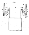
- the above arrange-ment is also provided on the opposite lateral surface of the bucket 5. In this way, the buckets 5 are attached to the pair of roller chains 4 (see Fig. 4).
- each guide plate 8 is semicircular and the sprocket wheels 10 and 11 of the same diameter are disposed close thereto and on a level with each other.
- the guide plate 8 and sprocket wheels 10 and 11 are disposed in the same vertical plane so that the rollers 21 of the roller chain 4 are in contact with and roll on the peripheral surface 8' of the guide plate 8.
- the guide plate 8 and sprocket wheels 10 and 11 are installed on each side of the path of travel of the buckets 5, as shown in Fig. 4.
- the character y indicates the path of travel of the roller chain 4 and x indicates the path of travel of the attaching shaft 15.
- a point A is the lowest point of travel of the attaching shaft 15 and is fixed and a point B is the lowest point of travel of the bucket shaft 18, said point B vertically varying with the weight of objects to be measured.
- a plurality of transfer and measuring lines (hereinafter referred to briefly as the lines) each comprising, as described above, the bucket conveyor 1 composed of the driving and driven sprocket wheels 2 and 3 and a number of buckets 5, the weighing unit 7, the discharge chute 12, and the guide plates 8 and sprocket wheels 10 and 11 for successively placing the buckets 5 on the weighing pan 9 of the weighing unit 7 are installed side by side and the bucket conveyors 1 are driven by the motor 6, each line operating by successively measuring the objects held in the buckets 5, storing a predetermined number of weight values, computing.
- the lines each comprising, as described above, the bucket conveyor 1 composed of the driving and driven sprocket wheels 2 and 3 and a number of buckets 5, the weighing unit 7, the discharge chute 12, and the guide plates 8 and sprocket wheels 10 and 11 for successively placing the buckets 5 on the weighing pan 9 of the weighing unit 7 are installed side by side and the bucket conveyors 1 are driven by the motor 6, each line operating by successively measuring the objects held
- the arrangement of the electronic circuitry of this invention will now be described with reference to Fig. 5.
- the numeral 22 denotes an input selector; 23 denotes an A/D converter; and 24 denotes a microcomputer (hereinafter referred to as CPU).
- CPU microcomputer
- analog weight signals from the weighing unit 7 are successively transferred from the input selector 22 one by one to the A/D converter 23, where they are converted into digital signals, which are then transferred to the CPU 24.
- the CPU receives a computation command signal ⁇ , a bucket detection signal ß and a tare storage signal ⁇ to control said input selector 22 and A/D converter 23 and perform tare subtractions, combinational computations and control of the tipping of buckets 5.
- the numeral 25 denotes a program storing section for storing programs for operation of the CPU 24; 26 denotes a tare storing section for scoring the respective weights of the buckets 5 as tares; 27 denotes a net weight storing section for storing the weight of objects to be weighed; 28 denotes an optimum combination storing section for storing a preset weight value or a value nearest thereto, i.e., an optimum combination at the end of combinational operation; and 29 denotes an indicating section for indicating the weight of objects being weighed, the preset weight vslue and the deviation of the total of the weights corresponding to the optimum combination.
- the numeral 30 denotes discharge drive sections each for driving the bucket tipping mechanism (not shown) which tips buckets 5 in the associated line when necessary, the arrangement being such that when a bucket 5 selected for combination reaches the discharge chute 12, a discharge command signal b from the CPU 24 actuates the bucket tipping mechanism. to tip the bucket 5 so as to discharge the objects therein into the discharge chute 12.
- the bucket conveyor 1 of each line is driven through one cycle so that the respective weights of the buckets 5 are successively measured by the associated weighing unit 7.
- the computation command signal ⁇ and tare storage command signal ⁇ have been inputted into the CPU 24.
- the respective weights of the buckets 5 are successively transferred in the form of an analog signals from the associated . weighing unit 7 to the input selector 22, from which said analog weight signals from the weighing unit 7 are then transferred one by one to the A/D converter 23 in response to control signals a from the CPU 24.
- the transferred weight signals are converted into digital signals by the A/D converter 23 and then transferred to the CPU 24.
- the respective weights of the buckets 5 are stored as tares in the tare storage section 26.
- the tare storage command signals e stored in the CPU 24 are automatically or manually released and then the bucket conveyor 1 is continuously driven while objects to be weighed are automatically or manually put successively into the buckets 5 moving on the conveyor 1.
- Buckets 5 which have said objects put therein are transferred along the lower run of the converyor towrrd the weighing unit 7.
- the buckets 5 are successively placed on the weighing pan 9 of the weighing unit 7 in the following manner.
- the attaching elements 16 fixed to the roller chains 4 being held vertical (see Fig. 2), and in this state the attaching elements 16 turn counterclockwise through 90° along the sprocket wheels 10 until they are horizontal, the path of travel of the attaching shafts 15 being indicated by the phantom line x.
- the attaching elements 16 descend in their horizontal state and the weighing pan 9 supporting the bucket 5 also descends but slightly, with the attaching shafts 15 separating from the attaching brackets 20 and descending to the position of the lowest point of travel A.
- the attaching shafts 15 have been completely isolated from the attaching brackets 20, allowing the bucket 5 to be supported on the weighing pan 9. In this state, the bucket 5 is weighed.
- the attaching elements 16 half turn clockwise around the lowest point of travel A along the guide plates 8 to resume the horizontal state and ascend in their horizontal state until the attaching shafts 15 again engage the attaching brackets 20.
- the bucket 5 the weighing of which has just been completed is supported again by the roller chains 4 and the attaching elements 16 ascend in their horizontal state and hence the weighing pan 9 ascends back to its original position.
- the attaching elements 16 ascending in their horizontal state lift the bucket 5 to separate it from the weighing pan 9 and turn counterclockwise through 90° along the sprocket wheels 11 to resume the vertical state (see Fig. 2).
- the bucket 5 is then transferred to a position above the discharge chute 12.
- the measured weight values provided by the weighing unit 7 in each line are transferred to the input selector 22 as analog weight signals and then transferred one by one to the A/D converter 23 in response to control signals a.
- the weight signals thus transferred are converted into digital weight signals by the A/D converter 23 and then transferred to the CPU 24.
- the weight of the corresponding bucket 5 is read out of the tare storage section 26 in which the respective weights of the buckets 5 are stored, and it is transferred to the CPU 24, where the net weight of the objects in each bucket is computed by subtracting the weight of the bucket 5 from the weight value from the A/D converter 23.
- the net weight thus computed is stored in the net ' weight storage section 27.
- the net weights of the objects in the respective buckets are successively computed and are stored in the net weight storage section 27 in groups each consisting of a predetermined number of, e.g., three net weights for each line.
- a predetermined number of e.g., three net weights for each line.
- a total of 9 weight values are used in the computation of a desired or predetermined number of combinations of such values which is performed in the CPU 24 and a particular combination of weight values which is equal or nearest to the preset weight is selected.
- the selected combination is stored in the storage section 28.
- the preset weight, the net weight of the objects being weighed and the deviation of the total weight values corresponding to the optimum combination from the preset value are indicated in the indication section 29.
- Buckets which have undergone weighing are successively conveyed and when they reach a position above the discharge chute 12, they are detected by a detector (not shown) and bucket detection signals/3 for each line are fed to the CPU 24.
- the CPU 24 judges whether or not such a signal ß corresponds to the signal associated with a bucket 5 corresponding to the combination stored in the optimum combination storage section 28 and if it does, the CPU 24 sends a discharge command signal b to the discharge drive section 30, with the result that the bucket tipping mechanism (not shown) is actuated to tip the corresponding bucket 5 to discharge the content thereof into the discharge chute 12.
- the objects discharged from the respective buckets corresponding to the combination stored in the optimum combination storage section 28 are collected in the timing hopper 14 by the collecting conveyor 13 and supplied to a packaging machine or the like (not shown).
- the buckets 5 emptied of their contents travel on the upper run of the bucket conveyor 1., during which objects to be weighed are put again into them manually or automatically.
- the number of buckets 5 in each line is a multiple of the number of weight values used in combinational computations for each line, plus or minus 1.
- the number of buckets 5 in each line is, e.g., 16. This measure prevents the same buckets 5 from being used in combinational computations.
- the number of buckets 5 present between the weighing unit 7 and the discharge chute 12 is equal to the number of weight values used for combinational computations in the illustrated embodiment, more buckets may be present. In that case, the capacity of the net weight storage section 27 must be increased.
- combinational computations are performed with 3 weight values in each line, namely, 9 weight values in total, but the number is not limited thereto; for example, the number of lines may be 4, and 2 weight values for each line and hence 8 weight values in total may be used to perform combinational computations. Thus, the number of weight values may be determined according to the need.
- the collecting conveyor 13 has been used to collect at a place the objects discharged from the respective lines, such a conveyor may not be used and instead the discharge chute 12 of each line may be extended to a position above the timing hopper 14.
- the means for placing the buckets 5 on the weighing unit 7 is not limited to the illustrated guide plates 8 and sprocket wheels 10, 11.
- the conveyors 1 may be either continuously or intermittently driven, but continuous drive is more preferable in consideration of impacts due to a repetition of stoppage.
Landscapes
- Physics & Mathematics (AREA)
- General Physics & Mathematics (AREA)
- Sorting Of Articles (AREA)
- Filling Or Emptying Of Bunkers, Hoppers, And Tanks (AREA)
Applications Claiming Priority (2)
| Application Number | Priority Date | Filing Date | Title |
|---|---|---|---|
| JP1161580A JPS56108917A (en) | 1980-02-01 | 1980-02-01 | Metering device |
| JP11615/80 | 1980-02-01 |
Publications (3)
| Publication Number | Publication Date |
|---|---|
| EP0045319A1 true EP0045319A1 (de) | 1982-02-10 |
| EP0045319A4 EP0045319A4 (de) | 1984-09-19 |
| EP0045319B1 EP0045319B1 (de) | 1988-04-27 |
Family
ID=11782814
Family Applications (1)
| Application Number | Title | Priority Date | Filing Date |
|---|---|---|---|
| EP81900325A Expired EP0045319B1 (de) | 1980-02-01 | 1981-01-26 | Wiegevorrichtung |
Country Status (7)
| Country | Link |
|---|---|
| US (1) | US4420051A (de) |
| EP (1) | EP0045319B1 (de) |
| JP (1) | JPS56108917A (de) |
| AU (1) | AU532321B2 (de) |
| DE (1) | DE3134403C2 (de) |
| GB (1) | GB2084744B (de) |
| WO (1) | WO1981002204A1 (de) |
Cited By (11)
| Publication number | Priority date | Publication date | Assignee | Title |
|---|---|---|---|---|
| FR2522141A1 (fr) * | 1982-02-24 | 1983-08-26 | Dalgaard Knut & Co As | Procede pour repartir un certain nombre de corps de poids differents en unites de poids predetermine et dispositif servant a mettre en oeuvre le procede |
| FR2564581A1 (fr) * | 1984-05-18 | 1985-11-22 | Fournials Jacky | Machine de pesage automatique |
| GB2191010A (en) * | 1986-05-21 | 1987-12-02 | Yamato Scale Co Ltd | Loading and weighing structure for combination weighing machine |
| EP0319225A3 (de) * | 1987-11-30 | 1990-10-10 | Kliklok Corporation | Methode und Apparat für lineare kombinatorische Wägung |
| EP0534889A3 (de) * | 1991-09-27 | 1993-05-19 | Talleres Daumar S.A. | Automatische Waage für Nahrungsmittel |
| US5317110A (en) * | 1991-09-27 | 1994-05-31 | Talleres Daumar S.A. | Automatic weighing machines for food products |
| FR2744984A1 (fr) * | 1996-02-15 | 1997-08-22 | Soral Ind | Dispositif permettant de former des lots de portions de denrees alimentaires d'un poids donne |
| ES2111477A1 (es) * | 1995-09-29 | 1998-03-01 | Daumar Talleres | Perfeccionamientos en maquinas automaticas pesadoras de productos diversos, particularmente alimenticios. |
| EP0849572A3 (de) * | 1996-12-20 | 1998-12-30 | KORSCH PRESSEN GmbH | Verfahren und Vorrichtung zur Kontolle der Tablettenparameter |
| EP0806638A4 (de) * | 1995-10-12 | 1999-12-22 | Yamato Scale Co Ltd | Verfahren und einrichtung zum wiegen von kombinationen |
| FR2842597A1 (fr) * | 2002-07-22 | 2004-01-23 | Talleres Daumar Sa | Peseuse automatique de produits en vrac |
Families Citing this family (28)
| Publication number | Priority date | Publication date | Assignee | Title |
|---|---|---|---|---|
| US4518699A (en) * | 1982-07-06 | 1985-05-21 | The Babcock & Wilcox Company | On-line coal analyzer |
| ES8403752A1 (es) * | 1983-05-17 | 1984-05-01 | Perez Galan Miguel A | Perfeccionamientos en maquinas pesadoras y selectoras de productos hortofruticolas y similares |
| GB2146131B (en) * | 1983-09-02 | 1987-03-04 | Autosystems Ltd | Weighing apparatus |
| US4621664A (en) * | 1984-10-03 | 1986-11-11 | Diffracto Ltd. | Filling machines |
| JPS63184020A (ja) * | 1987-12-22 | 1988-07-29 | Anritsu Corp | 計量装置 |
| US5497887A (en) * | 1988-03-15 | 1996-03-12 | Autoline, Inc. | Method and apparatus for handling objects |
| JPH01118725A (ja) * | 1988-09-17 | 1989-05-11 | Anritsu Corp | 組合せ計量装置 |
| JPH0299325U (de) * | 1989-01-27 | 1990-08-08 | ||
| US5319160A (en) * | 1990-12-14 | 1994-06-07 | Nambu Electric Co., Ltd. | Apparatus for collecting an article |
| US5244100A (en) * | 1991-04-18 | 1993-09-14 | Regier Robert D | Apparatus and method for sorting objects |
| DE4124194C1 (de) * | 1991-07-20 | 1992-12-03 | Naehmaschinenfabrik Emil Stutznaecker Gmbh & Co Kg, 5000 Koeln, De | |
| DE19536871B4 (de) * | 1995-10-03 | 2004-09-30 | Maschinenfabrik Besta Gmbh & Co | Bunkerabzugs- und Aufgabeplattenband mit automatischer Wiege- und Dosiereinrichtung für Schüttgüter |
| US5986219A (en) * | 1998-01-14 | 1999-11-16 | Bar Beverage Control, Inc. | Method of inventorying liquor |
| ES2152797B1 (es) * | 1998-02-25 | 2001-08-16 | Daumar Talleres | Perfeccionamientos en maquinas pesadoras automaticas de productos, especialmente alimenticios. |
| ES2153749B1 (es) * | 1998-08-25 | 2003-08-16 | Olaechea Rosalina Paniagua | Maquina pesadora automatica de frutas y similares. |
| US6580038B1 (en) | 2000-01-19 | 2003-06-17 | Gainco Inc. | Static weighing system |
| DE10130022A1 (de) * | 2001-06-25 | 2003-01-02 | Pfister Gmbh | Kettenförderer in Waagenform |
| US6662930B2 (en) * | 2001-07-31 | 2003-12-16 | Metso Minerals Industries Inc. | Apron weigh feeder |
| ES2234358B1 (es) * | 2002-07-22 | 2006-01-16 | Talleres Daumar, S.A. | Pesadora automatica de productos a granel. |
| ES2232240B1 (es) * | 2002-08-13 | 2006-02-16 | Rosalina Paniagua Olaechea | Maquina para pesado y clasificacion de piezas de fruta y similares. |
| DE112004001877T5 (de) * | 2003-10-10 | 2006-11-30 | Ishida Co., Ltd. | Wiegevorrichtung, Kombinationswiegevorrichtung, welche dieselbe enthält, und Wiegeverfahren |
| US7241955B2 (en) * | 2004-01-30 | 2007-07-10 | Bakery Systems, Inc. | Method and apparatus for weighing divided portions |
| US7154055B2 (en) * | 2004-03-08 | 2006-12-26 | Bakery Systems, Inc. | Method and apparatus for dividing portions |
| JP5034099B2 (ja) * | 2005-09-26 | 2012-09-26 | 株式会社イシダ | 組合せ計量装置およびこれを備えた製袋包装システム、組合せ計量システム |
| JP5015639B2 (ja) * | 2007-03-16 | 2012-08-29 | 勝三 川西 | 連係装置とそれを用いた計量装置、包装装置及び計量包装システム |
| US10098355B2 (en) | 2014-11-19 | 2018-10-16 | Bakery Systems, Inc. | System and method for weighing items |
| JP7491543B2 (ja) * | 2019-09-26 | 2024-05-28 | 株式会社イシダ | 計量装置 |
| US20240081348A1 (en) * | 2022-09-12 | 2024-03-14 | AMF Bakery Systems | Apparatus and Method with Integrated Process Checkweigher for Commercial Bread Product Manufacture |
Family Cites Families (15)
| Publication number | Priority date | Publication date | Assignee | Title |
|---|---|---|---|---|
| US285663A (en) * | 1883-09-25 | pearce | ||
| US2716479A (en) * | 1954-02-09 | 1955-08-30 | Western Electric Co | Transporting apparatus |
| DE1275785B (de) * | 1964-08-12 | 1968-08-22 | Bahlsen Werner | Waegevorrichtung |
| JPS449899Y1 (de) * | 1965-12-03 | 1969-04-21 | ||
| US3528518A (en) * | 1967-08-03 | 1970-09-15 | Howe Richardson Scale Co | Automatic batch weigher |
| US3939928A (en) * | 1972-08-12 | 1976-02-24 | Kabushiki Kaisha Ishida Koki Seisakusyo | Weighing method and apparatus |
| JPS5414946B2 (de) * | 1972-08-12 | 1979-06-11 | ||
| US3997013A (en) * | 1973-08-07 | 1976-12-14 | Autosystems Limited | Sorting systems and sensing devices for use therewith |
| JPS5443908B2 (de) * | 1973-09-01 | 1979-12-22 | ||
| DE2600494A1 (de) * | 1976-01-08 | 1977-07-14 | Friedrich Segler Maschinenfabr | Becherwerk |
| US4163488A (en) * | 1976-01-28 | 1979-08-07 | Auto Systems Limited | Conveyor systems |
| JPS5690219A (en) * | 1979-12-24 | 1981-07-22 | Yamato Scale Co Ltd | Combination scale |
| US4344492A (en) * | 1980-04-14 | 1982-08-17 | Yamato Scale Co. Ltd. | Automatic combination weighing machine with improved zero-point correction |
| US4308928A (en) * | 1980-06-30 | 1982-01-05 | Yamato Scale Company Limited | Automatic combination weighing machine |
| DE3042902A1 (de) * | 1980-11-14 | 1982-06-16 | Ferd. Schulze & Co, 6800 Mannheim | Elektromechanische waage |
-
1980
- 1980-02-01 JP JP1161580A patent/JPS56108917A/ja active Pending
-
1981
- 1981-01-26 GB GB8127851A patent/GB2084744B/en not_active Expired
- 1981-01-26 EP EP81900325A patent/EP0045319B1/de not_active Expired
- 1981-01-26 WO PCT/JP1981/000017 patent/WO1981002204A1/ja not_active Ceased
- 1981-01-26 AU AU67713/81A patent/AU532321B2/en not_active Ceased
- 1981-01-26 DE DE3134403T patent/DE3134403C2/de not_active Expired
- 1981-01-26 US US06/308,547 patent/US4420051A/en not_active Expired - Lifetime
Cited By (12)
| Publication number | Priority date | Publication date | Assignee | Title |
|---|---|---|---|---|
| FR2522141A1 (fr) * | 1982-02-24 | 1983-08-26 | Dalgaard Knut & Co As | Procede pour repartir un certain nombre de corps de poids differents en unites de poids predetermine et dispositif servant a mettre en oeuvre le procede |
| FR2564581A1 (fr) * | 1984-05-18 | 1985-11-22 | Fournials Jacky | Machine de pesage automatique |
| GB2191010A (en) * | 1986-05-21 | 1987-12-02 | Yamato Scale Co Ltd | Loading and weighing structure for combination weighing machine |
| GB2191010B (en) * | 1986-05-21 | 1990-05-23 | Yamato Scale Co Ltd | Loading and weighing structure for combination weighing machine |
| EP0319225A3 (de) * | 1987-11-30 | 1990-10-10 | Kliklok Corporation | Methode und Apparat für lineare kombinatorische Wägung |
| EP0534889A3 (de) * | 1991-09-27 | 1993-05-19 | Talleres Daumar S.A. | Automatische Waage für Nahrungsmittel |
| US5317110A (en) * | 1991-09-27 | 1994-05-31 | Talleres Daumar S.A. | Automatic weighing machines for food products |
| ES2111477A1 (es) * | 1995-09-29 | 1998-03-01 | Daumar Talleres | Perfeccionamientos en maquinas automaticas pesadoras de productos diversos, particularmente alimenticios. |
| EP0806638A4 (de) * | 1995-10-12 | 1999-12-22 | Yamato Scale Co Ltd | Verfahren und einrichtung zum wiegen von kombinationen |
| FR2744984A1 (fr) * | 1996-02-15 | 1997-08-22 | Soral Ind | Dispositif permettant de former des lots de portions de denrees alimentaires d'un poids donne |
| EP0849572A3 (de) * | 1996-12-20 | 1998-12-30 | KORSCH PRESSEN GmbH | Verfahren und Vorrichtung zur Kontolle der Tablettenparameter |
| FR2842597A1 (fr) * | 2002-07-22 | 2004-01-23 | Talleres Daumar Sa | Peseuse automatique de produits en vrac |
Also Published As
| Publication number | Publication date |
|---|---|
| JPS56108917A (en) | 1981-08-28 |
| DE3134403T1 (de) | 1982-05-06 |
| AU532321B2 (en) | 1983-09-22 |
| GB2084744B (en) | 1984-05-16 |
| WO1981002204A1 (fr) | 1981-08-06 |
| GB2084744A (en) | 1982-04-15 |
| DE3134403C2 (de) | 1986-03-27 |
| EP0045319B1 (de) | 1988-04-27 |
| EP0045319A4 (de) | 1984-09-19 |
| AU6771381A (en) | 1981-08-17 |
| US4420051A (en) | 1983-12-13 |
Similar Documents
| Publication | Publication Date | Title |
|---|---|---|
| US4420051A (en) | Weighing apparatus | |
| EP1176405B1 (de) | Kombinationswaage mit einer Versorgungseinheit | |
| US4661917A (en) | Mixing combinatorial counting and weighing method, and apparatus therefor | |
| US3734215A (en) | Continuous flow scale with alternating volumetric measuring and weighing chambers | |
| EP2669643B1 (de) | Mehrkopfwaage | |
| EP0806638B1 (de) | Verfahren und einrichtung zum wiegen von kombinationen | |
| EP2693175B1 (de) | Mehrkopfwaage | |
| US4442932A (en) | Combinatorial weighing apparatus | |
| EP0097532B1 (de) | Kombinatorischer Wägeapparat | |
| WO1992010728A1 (fr) | Dispositif de ramassage d'articles | |
| EP0642002A2 (de) | Kombinatorisches Wägesystem und Verfahren | |
| EP0099238B1 (de) | Warenentladeapparat zum Gebrauch in einem automatischen Wägesystem | |
| EP0076108A2 (de) | Kombinatorischer Wiegeapparat | |
| JPH02657Y2 (de) | ||
| US3690392A (en) | Continuous flow scale with preliminary volumetric measurement | |
| US4511009A (en) | Combinatorial weighing apparatus and method | |
| JP2630368B2 (ja) | 計量装置 | |
| US4726434A (en) | Metal detector testing process and apparatus in a combination weighing system | |
| EP0076113A2 (de) | Wiegeapparatur mit einer Reihe von Wiegemaschinen | |
| JP3069978B2 (ja) | 大根類の重量選別機 | |
| JPH0216978B2 (de) | ||
| JP3647549B2 (ja) | 組合せ秤 | |
| JP3367037B2 (ja) | 組合せ計量装置 | |
| RU2068548C1 (ru) | Дозатор | |
| US4611706A (en) | Method and apparatus for packing fruit |
Legal Events
| Date | Code | Title | Description |
|---|---|---|---|
| PUAI | Public reference made under article 153(3) epc to a published international application that has entered the european phase |
Free format text: ORIGINAL CODE: 0009012 |
|
| 17P | Request for examination filed |
Effective date: 19810921 |
|
| AK | Designated contracting states |
Designated state(s): FR |
|
| 17Q | First examination report despatched |
Effective date: 19860129 |
|
| GRAA | (expected) grant |
Free format text: ORIGINAL CODE: 0009210 |
|
| AK | Designated contracting states |
Kind code of ref document: B1 Designated state(s): FR |
|
| ET | Fr: translation filed | ||
| PLBE | No opposition filed within time limit |
Free format text: ORIGINAL CODE: 0009261 |
|
| STAA | Information on the status of an ep patent application or granted ep patent |
Free format text: STATUS: NO OPPOSITION FILED WITHIN TIME LIMIT |
|
| 26N | No opposition filed | ||
| PGFP | Annual fee paid to national office [announced via postgrant information from national office to epo] |
Ref country code: FR Payment date: 20000112 Year of fee payment: 20 |