EP0045337A1 - Befestigung eines weichen Materials an einer Struktur - Google Patents
Befestigung eines weichen Materials an einer Struktur Download PDFInfo
- Publication number
- EP0045337A1 EP0045337A1 EP19800401153 EP80401153A EP0045337A1 EP 0045337 A1 EP0045337 A1 EP 0045337A1 EP 19800401153 EP19800401153 EP 19800401153 EP 80401153 A EP80401153 A EP 80401153A EP 0045337 A1 EP0045337 A1 EP 0045337A1
- Authority
- EP
- European Patent Office
- Prior art keywords
- rigid
- flexible material
- plane
- cell
- attachment
- Prior art date
- Legal status (The legal status is an assumption and is not a legal conclusion. Google has not performed a legal analysis and makes no representation as to the accuracy of the status listed.)
- Ceased
Links
- 239000000463 material Substances 0.000 title claims abstract description 43
- 238000000034 method Methods 0.000 claims abstract description 9
- 210000004027 cell Anatomy 0.000 claims 2
- 210000002199 attachment cell Anatomy 0.000 claims 1
- 230000000694 effects Effects 0.000 description 5
- 238000004026 adhesive bonding Methods 0.000 description 3
- 238000003466 welding Methods 0.000 description 3
- 238000002788 crimping Methods 0.000 description 2
- 238000000605 extraction Methods 0.000 description 2
- 210000003456 pulmonary alveoli Anatomy 0.000 description 2
- 238000009958 sewing Methods 0.000 description 2
- 241001080024 Telles Species 0.000 description 1
- 230000001154 acute effect Effects 0.000 description 1
- 238000005452 bending Methods 0.000 description 1
- 208000018747 cerebellar ataxia with neuropathy and bilateral vestibular areflexia syndrome Diseases 0.000 description 1
- 238000010276 construction Methods 0.000 description 1
- 238000009826 distribution Methods 0.000 description 1
- PCHJSUWPFVWCPO-UHFFFAOYSA-N gold Chemical compound [Au] PCHJSUWPFVWCPO-UHFFFAOYSA-N 0.000 description 1
- 239000010931 gold Substances 0.000 description 1
- 229910052737 gold Inorganic materials 0.000 description 1
- 238000009776 industrial production Methods 0.000 description 1
- 239000010985 leather Substances 0.000 description 1
- 239000007788 liquid Substances 0.000 description 1
- 238000004806 packaging method and process Methods 0.000 description 1
- 238000006116 polymerization reaction Methods 0.000 description 1
- 230000002787 reinforcement Effects 0.000 description 1
- 239000000126 substance Substances 0.000 description 1
- 230000001629 suppression Effects 0.000 description 1
- 229920001187 thermosetting polymer Polymers 0.000 description 1
- 238000009827 uniform distribution Methods 0.000 description 1
Images
Classifications
-
- A—HUMAN NECESSITIES
- A45—HAND OR TRAVELLING ARTICLES
- A45F—TRAVELLING OR CAMP EQUIPMENT: SACKS OR PACKS CARRIED ON THE BODY
- A45F5/00—Holders or carriers for hand articles; Holders or carriers for use while travelling or camping
-
- B—PERFORMING OPERATIONS; TRANSPORTING
- B65—CONVEYING; PACKING; STORING; HANDLING THIN OR FILAMENTARY MATERIAL
- B65H—HANDLING THIN OR FILAMENTARY MATERIAL, e.g. SHEETS, WEBS, CABLES
- B65H75/00—Storing webs, tapes, or filamentary material, e.g. on reels
- B65H75/02—Cores, formers, supports, or holders for coiled, wound, or folded material, e.g. reels, spindles, bobbins, cop tubes, cans, mandrels or chucks
- B65H75/18—Constructional details
- B65H75/28—Arrangements for positively securing ends of material
Definitions
- the present invention relates to a method for hanging a flexible material, shaped into wire, tape or sheet, on a rigid part, and concerns all the fields of activity where such a problem must be resolved, nar example: handling (hanging of slings), packaging (fixing of ribbons or rolls on reel, as for typewriters), furniture (fixing of panels, curtains, canvases of hamecs, etc.), leather goods, saddlery and tools (kits and various cases that can be worn attached to the belt), sports equipment (quiver, sails, hanging of tensioners, attachment of ropes on capstan drum); door interlocker, etc.
- handling hanging of slings
- packaging fixing of ribbons or rolls on reel, as for typewriters
- furniture fixing of panels, curtains, canvases of hamecs, etc.
- leather goods leather goods
- saddlery and tools kits and various cases that can be worn attached to the belt
- sports equipment quiver, sails, hanging of tensioners, attachment of ropes on capstan drum
- door interlocker etc
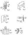
- the invention is characterized in that, at each of its attachment points, the material (1), flexible in the direction of FIG. 1, is made rigid over a certain portion (2) of its dimension along the plane of the figure, and that this rigid part (2) is introduced into the cell (3) of a rigid part (4).
- the length, in the plane of the rigid part (2) is less than the depth of the cell (3) but much greater than its width, so that the traction exerted upwards on the upper part (1) of the material flexible has the effect of applying this material on the right edge of the cell (3), and this traction has the effect of bracing the rigid part (2) against the left wall of the cell (3).
- the more the equilibrium position of this rigid part (2) is close to the axis of the cell (3) according to the plane of the figure, the less the bending forces which it must balance by its rigidity.
- the invention is characterized by the mere fact of making the flexible material rigid in one of its parts such as (2) defining a point of attachment, and not by the means used to obtain this result.
- Figure 1 shows a section of a point of dislocation but the dimension of the socket and the parts in contact is not specified in the direction porpendiculaipe in the plane of the figure. From this point of view, it should be specified that, if the flexible material (1) is in the form of a sheet or, at least, of a fairly wide gold ribbon or strap, that is to say -to say that its dimension perpendicular to the plane of the figure is at least of the order of ten times its thickness represented in the plen of the figure, its rigidity in a plane perpendicular to the plane of the figure is sufficient for that the cell (3) does not need side walls above and below the plane of the figure.
- the flexible material (1) is in the form of wire or cable, that is to say that its dimension perpendicular to the plane of the figure is approximately equal to its thickness measured in the plane of Figure 1, it is absolutely necessary that the cell (3) has side walls above and below the plane of Figure 1 to guide and maintain the rigid part (2) in the plane of the figure.
- FIG. 1 shows a piece (4) attached to a piece (1) of flexible material; but by symmetry about a horizontal axis contained in the plane of the figure, the alveolus (3) would come on top of the part (4) and the part (1) of the flexible material would hang, hooked to the part ( 4). More generally, whatever its orientation, FIG. 1 represents the attachment of the flexible material 1 on which a traction is exerted tending to move it away from the part (4) in a direction parallel to the axis of the cell (3) and in a direction such that this traction applies the flexible material to the edge of the cell (3) and causes the bracing of the rigid part (2) against the edge of the opposite cell (3) to the previous one.
- FIG. 3 which represents a portion of tube (7) fixed by gluing or welding to a part (8) is the counterpart of FIG. 2 in the case, no longer of a strap or of a ribbon, but of a wire or cable.
- the material (8) is sufficiently resistant and if it can be pierced with a through hole sufficiently close to its outer surface, the attached tube (7) can very well be replaced by such a hole.
- FIG. 4 represents a device for attaching to a belt a piece of flexible material (9), for example a case or quiver, terminated by a part (10) made rigid in the plane of the figure.
- the rigidity in the plane of Figure 4 is mandatory for the attachment, but the flexibility of the part (10) around an axis contained in the plane of Figure 4 may be necessary to follow a curved wall in the same meaning.
- the part (10) (fig. 4, fig. 5 and fig. 6) is made rigid in a single plane by means of mutually parallel reinforcements such as (11), which allow the part (10 ) around a vertical axis of Figure 5, but not around a horizontal axis of this same figure.
- Figure 6 shows a section seen from above of the attachment made by means of parts such as (9), (10) and (11) on a bar such as (5), in the case where the wall (6) of Figure 2 is convex.
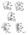
- Figures 7 and 8 show another embodiment of a hooking of a flexible material (13), (14) of which a part (15) has been made rigid in the plane of the figure, on a rigid part (12), (16).
- the traction exerted on the part (13) of the flexible material is transmitted by the rigidity of the part (15) which causes the jamming of the free strand (14) in the acute dihedron of edge perpendicular to the plane of the figure. , which is formed by the part (16) and the lower lip (12) of the attachment socket.
- Figure 7 shows this latching in the locked position and Figure 8, the same during engagement or disengagement, the part (13) not being subjected to traction.
- Figure 9 is a variant of the figure? where, the rigid part (15) not being able to slide along the flexible material under the action of the traction exerted at (13), the pinching exerted between (16) and (12) of FIG. 7 does not is no longer necessary and a simple bracing of the end of the rigid part (15) against the bottom of the cell is sufficient.
- the rigid portion (15) could be produced by means of a sheath of rigid material in which the flexible material can slide.
- the rigid portion (15) would for example be produced by bonding rigid plates to the flexible material, or else by threading rigid plates into gussets formed by the flexible material.
- FIGS. 7, 8, 9, 10 and 11 has been shown, delimited by a dashed line, the zone of clearance necessary for detachment, which is produced by extraction of the rigid part of the flexible material from the catching alveolus .
- the tension exerted on the part (13) must be released in the case of FIGS. 7, 8 and 9, and the extraction of the rigid part (15) from the cell is obtained by pulling on the part (14) of the flexible material.
- the lower part of the attachment socket consists of a rigid part (18) with a cross-section in the plane of the figure, the dimension of which is perpendicular to the plane of the figure is the same as that of the parts (13), (14), (15) and (17), and which is movable around an axis (19) integral with the support (17).
- the axis (19) perpendicular to the plane of the figure is located as close as possible to the rectilinear wall of the part (17), but at a distance at least equal to the sum of the thickness of the rigid part (15) and free strand (14).
- the traction on the part (13) presses the part (15) and the strand loop (14) on the horizontal wing of the bracket (18) causing the part (15) and the strand (14) to be pinched between the vertical wing of the bracket (18) and the part (17).
- a moderate traction exerted on (14) allows the rotation to the right of the square (18) around its axis (19) and the release of the rigid part (15), even in the presence of a traction on the part ( 13).
- FIG. 11 responds to the same explanations of operation as in FIG. 10, with the exception of the replacement of the rigid part (15) of the flexible material with a piece (20) of rigid material against which the flexible material is simply applied under the effect of the traction exerted at (13), and which causes pinching of the flexible material and its application against the rigid part (20) along the two branches of the bracket (18) and the part (17).
- the profile shown in FIG. 11 for the rigid part (20) constitutes only one example of embodiment of an apparently rigid zone, on the flexible material, simply by its application under tension along a rigid part (20). , with which he is in no way linked and of which he is separates spontaneously when it comes off when the square is "opened” by rotation to the right by pulling on the free part (14).
Landscapes
- Clamps And Clips (AREA)
- Package Frames And Binding Bands (AREA)
- Curtains And Furnishings For Windows Or Doors (AREA)
Priority Applications (3)
| Application Number | Priority Date | Filing Date | Title |
|---|---|---|---|
| EP19800401153 EP0045337A1 (de) | 1980-08-05 | 1980-08-05 | Befestigung eines weichen Materials an einer Struktur |
| CA000379430A CA1164633A (fr) | 1980-08-05 | 1981-06-10 | Procede d'accrochage sur une piece rigide d'un materiau souple faconne en fil, ruban ou feuille |
| JP9366781A JPS5733208A (en) | 1980-08-05 | 1981-06-17 | Clamp member and manufacture thereof |
Applications Claiming Priority (1)
| Application Number | Priority Date | Filing Date | Title |
|---|---|---|---|
| EP19800401153 EP0045337A1 (de) | 1980-08-05 | 1980-08-05 | Befestigung eines weichen Materials an einer Struktur |
Publications (1)
| Publication Number | Publication Date |
|---|---|
| EP0045337A1 true EP0045337A1 (de) | 1982-02-10 |
Family
ID=8187390
Family Applications (1)
| Application Number | Title | Priority Date | Filing Date |
|---|---|---|---|
| EP19800401153 Ceased EP0045337A1 (de) | 1980-08-05 | 1980-08-05 | Befestigung eines weichen Materials an einer Struktur |
Country Status (3)
| Country | Link |
|---|---|
| EP (1) | EP0045337A1 (de) |
| JP (1) | JPS5733208A (de) |
| CA (1) | CA1164633A (de) |
Citations (12)
| Publication number | Priority date | Publication date | Assignee | Title |
|---|---|---|---|---|
| US1392321A (en) * | 1920-04-06 | 1921-10-04 | William F Gammeter | Stock-roll |
| US1757241A (en) * | 1926-12-02 | 1930-05-06 | Harry D Forse | Fabric anchorage |
| US1867488A (en) * | 1930-03-03 | 1932-07-12 | Barr Jesse Paul | Camera film and spool loading device |
| US1871234A (en) * | 1929-01-16 | 1932-08-09 | Kinatome Patents Corp | Container for films and means for handling the same |
| US2006663A (en) * | 1933-12-21 | 1935-07-02 | Miller Bryant Pierce Co | Ribbon spool |
| US2237737A (en) * | 1939-10-25 | 1941-04-08 | Houston Corp | Photographic film developing apparatus |
| DE807455C (de) * | 1949-07-23 | 1951-06-28 | Otto W Krause | Einrichtung zum Befestigen von Filmstreifen an der Spule einer Filmentwicklungsdose |
| US3147896A (en) * | 1960-06-30 | 1964-09-08 | Howard A Kehl | Safety belt billfold |
| DE1900450U (de) * | 1964-05-02 | 1964-09-10 | Max Grundig | Spule fuer baender, z. b. magnetbaender. |
| US3738551A (en) * | 1971-10-05 | 1973-06-12 | H Dieter | Article holding device |
| CH550735A (de) * | 1971-05-06 | 1974-06-28 | Fabers Chr As Fabriker | Einrichtung fuer die befestigung einer materialbahn an einer stange. |
| DE2817160A1 (de) * | 1978-04-20 | 1979-10-25 | Hecking Jutta | Klemmvorrichtung |
-
1980
- 1980-08-05 EP EP19800401153 patent/EP0045337A1/de not_active Ceased
-
1981
- 1981-06-10 CA CA000379430A patent/CA1164633A/fr not_active Expired
- 1981-06-17 JP JP9366781A patent/JPS5733208A/ja active Pending
Patent Citations (12)
| Publication number | Priority date | Publication date | Assignee | Title |
|---|---|---|---|---|
| US1392321A (en) * | 1920-04-06 | 1921-10-04 | William F Gammeter | Stock-roll |
| US1757241A (en) * | 1926-12-02 | 1930-05-06 | Harry D Forse | Fabric anchorage |
| US1871234A (en) * | 1929-01-16 | 1932-08-09 | Kinatome Patents Corp | Container for films and means for handling the same |
| US1867488A (en) * | 1930-03-03 | 1932-07-12 | Barr Jesse Paul | Camera film and spool loading device |
| US2006663A (en) * | 1933-12-21 | 1935-07-02 | Miller Bryant Pierce Co | Ribbon spool |
| US2237737A (en) * | 1939-10-25 | 1941-04-08 | Houston Corp | Photographic film developing apparatus |
| DE807455C (de) * | 1949-07-23 | 1951-06-28 | Otto W Krause | Einrichtung zum Befestigen von Filmstreifen an der Spule einer Filmentwicklungsdose |
| US3147896A (en) * | 1960-06-30 | 1964-09-08 | Howard A Kehl | Safety belt billfold |
| DE1900450U (de) * | 1964-05-02 | 1964-09-10 | Max Grundig | Spule fuer baender, z. b. magnetbaender. |
| CH550735A (de) * | 1971-05-06 | 1974-06-28 | Fabers Chr As Fabriker | Einrichtung fuer die befestigung einer materialbahn an einer stange. |
| US3738551A (en) * | 1971-10-05 | 1973-06-12 | H Dieter | Article holding device |
| DE2817160A1 (de) * | 1978-04-20 | 1979-10-25 | Hecking Jutta | Klemmvorrichtung |
Also Published As
| Publication number | Publication date |
|---|---|
| JPS5733208A (en) | 1982-02-23 |
| CA1164633A (fr) | 1984-04-03 |
Similar Documents
| Publication | Publication Date | Title |
|---|---|---|
| US4365391A (en) | Device for locking and adjusting straps for lifting and securing apparatuses | |
| FR2743784A1 (fr) | Distributeur pour sacs et sacs utilises avec celui-ci | |
| FR2811972A1 (fr) | Procede de montage simultane de plusieurs courroies d'acier revetues dans une installation d'ascenseurs, distributeur et attache pour la mise en oeuvre de ce procede | |
| EP3936733B1 (de) | Materialhalterungsvorrichtung | |
| FR2740507A1 (fr) | Dispositif de securite pour echelle et echelle equipee d'un tel dispositif | |
| CA1164633A (fr) | Procede d'accrochage sur une piece rigide d'un materiau souple faconne en fil, ruban ou feuille | |
| EP0635290B1 (de) | Flugdrachen mit Vertiefungsarmierung | |
| EP0915195B1 (de) | Vorrichtung zur Verbindung einer Weblitze mit einer Harnischkordel, Weblitze mit einer solchen Vorrichtung sowie Webmaschine mit einer solchen Weblitze | |
| CH661849A5 (fr) | Boucle. | |
| EP0457696A1 (de) | System zur Befestigung der Zugkabeln auf den Zughebeln von negativen Schaftmaschinen | |
| FR3066461B1 (fr) | Volet antichute pour module logistique | |
| EP4074383B1 (de) | Seilgurtzeug mit verbesserter befestigung und herstellungsverfahren | |
| CA2109409C (fr) | Pince a linge magique | |
| BE518881A (de) | ||
| EP0209475A1 (de) | Mehrfachrollbaum zum Aufwickeln eines Bootsegels | |
| WO2009133250A1 (fr) | Pince d'ancrage pour câble de télécommunications | |
| FR2578804A1 (fr) | Arretoir pour boucle equipant une courroie de cale-pied. | |
| FR2981415A3 (fr) | Element de lien pour fixer ensemble deux corps oblongs. | |
| FR2924314A1 (fr) | Dispositif amovible permettant de saisir et manipuler des objets souples et enroulables | |
| FR2873663A1 (fr) | Distributeur de sacs plastiques disposes a cheval sur un bord du distributeur | |
| BE452225A (de) | ||
| FR2550288A1 (fr) | Dispositif d'accrochage d'une toile ou d'un film plastique sur un support | |
| BE485801A (de) | ||
| BE897094A (fr) | Un dispositif de suspension pour objets plans tels que des rideaux, des etoffes,du papier des pieces d'habillement des tableaux des decorations et objets analogues | |
| EP0326473A1 (de) | Befestigungsverfahren und -system für eine Schnalle an einem Gurt aus Elastomer |
Legal Events
| Date | Code | Title | Description |
|---|---|---|---|
| PUAI | Public reference made under article 153(3) epc to a published international application that has entered the european phase |
Free format text: ORIGINAL CODE: 0009012 |
|
| 17P | Request for examination filed |
Effective date: 19800925 |
|
| AK | Designated contracting states |
Designated state(s): BE CH DE FR GB IT LU |
|
| STAA | Information on the status of an ep patent application or granted ep patent |
Free format text: STATUS: THE APPLICATION HAS BEEN REFUSED |
|
| 18R | Application refused |
Effective date: 19841006 |