EP0045973B1 - Amortisseur de choc - Google Patents
Amortisseur de choc Download PDFInfo
- Publication number
- EP0045973B1 EP0045973B1 EP81106291A EP81106291A EP0045973B1 EP 0045973 B1 EP0045973 B1 EP 0045973B1 EP 81106291 A EP81106291 A EP 81106291A EP 81106291 A EP81106291 A EP 81106291A EP 0045973 B1 EP0045973 B1 EP 0045973B1
- Authority
- EP
- European Patent Office
- Prior art keywords
- chamber
- vortex
- piston
- valve
- fluid
- Prior art date
- Legal status (The legal status is an assumption and is not a legal conclusion. Google has not performed a legal analysis and makes no representation as to the accuracy of the status listed.)
- Expired
Links
- 230000035939 shock Effects 0.000 title claims description 42
- 239000006096 absorbing agent Substances 0.000 title claims description 29
- 239000012530 fluid Substances 0.000 claims description 74
- 238000004891 communication Methods 0.000 claims description 11
- 230000000903 blocking effect Effects 0.000 claims 1
- 230000004048 modification Effects 0.000 description 3
- 238000012986 modification Methods 0.000 description 3
- 238000010276 construction Methods 0.000 description 2
- 230000000694 effects Effects 0.000 description 2
- 239000000725 suspension Substances 0.000 description 2
- 230000006835 compression Effects 0.000 description 1
- 238000007906 compression Methods 0.000 description 1
- 238000003754 machining Methods 0.000 description 1
- 238000004519 manufacturing process Methods 0.000 description 1
- 238000000034 method Methods 0.000 description 1
- 238000005192 partition Methods 0.000 description 1
- 238000007789 sealing Methods 0.000 description 1
Images


Classifications
-
- F—MECHANICAL ENGINEERING; LIGHTING; HEATING; WEAPONS; BLASTING
- F16—ENGINEERING ELEMENTS AND UNITS; GENERAL MEASURES FOR PRODUCING AND MAINTAINING EFFECTIVE FUNCTIONING OF MACHINES OR INSTALLATIONS; THERMAL INSULATION IN GENERAL
- F16F—SPRINGS; SHOCK-ABSORBERS; MEANS FOR DAMPING VIBRATION
- F16F9/00—Springs, vibration-dampers, shock-absorbers, or similarly-constructed movement-dampers using a fluid or the equivalent as damping medium
- F16F9/32—Details
- F16F9/34—Special valve constructions; Shape or construction of throttling passages
- F16F9/344—Vortex flow passages
-
- B—PERFORMING OPERATIONS; TRANSPORTING
- B60—VEHICLES IN GENERAL
- B60G—VEHICLE SUSPENSION ARRANGEMENTS
- B60G13/00—Resilient suspensions characterised by arrangement, location or type of vibration dampers
- B60G13/02—Resilient suspensions characterised by arrangement, location or type of vibration dampers having dampers dissipating energy, e.g. frictionally
- B60G13/06—Resilient suspensions characterised by arrangement, location or type of vibration dampers having dampers dissipating energy, e.g. frictionally of fluid type
- B60G13/08—Resilient suspensions characterised by arrangement, location or type of vibration dampers having dampers dissipating energy, e.g. frictionally of fluid type hydraulic
-
- Y—GENERAL TAGGING OF NEW TECHNOLOGICAL DEVELOPMENTS; GENERAL TAGGING OF CROSS-SECTIONAL TECHNOLOGIES SPANNING OVER SEVERAL SECTIONS OF THE IPC; TECHNICAL SUBJECTS COVERED BY FORMER USPC CROSS-REFERENCE ART COLLECTIONS [XRACs] AND DIGESTS
- Y10—TECHNICAL SUBJECTS COVERED BY FORMER USPC
- Y10T—TECHNICAL SUBJECTS COVERED BY FORMER US CLASSIFICATION
- Y10T137/00—Fluid handling
- Y10T137/206—Flow affected by fluid contact, energy field or coanda effect [e.g., pure fluid device or system]
- Y10T137/2087—Means to cause rotational flow of fluid [e.g., vortex generator]
- Y10T137/2093—Plural vortex generators
-
- Y—GENERAL TAGGING OF NEW TECHNOLOGICAL DEVELOPMENTS; GENERAL TAGGING OF CROSS-SECTIONAL TECHNOLOGIES SPANNING OVER SEVERAL SECTIONS OF THE IPC; TECHNICAL SUBJECTS COVERED BY FORMER USPC CROSS-REFERENCE ART COLLECTIONS [XRACs] AND DIGESTS
- Y10—TECHNICAL SUBJECTS COVERED BY FORMER USPC
- Y10T—TECHNICAL SUBJECTS COVERED BY FORMER US CLASSIFICATION
- Y10T137/00—Fluid handling
- Y10T137/206—Flow affected by fluid contact, energy field or coanda effect [e.g., pure fluid device or system]
- Y10T137/2087—Means to cause rotational flow of fluid [e.g., vortex generator]
- Y10T137/2098—Vortex generator as control for system
-
- Y—GENERAL TAGGING OF NEW TECHNOLOGICAL DEVELOPMENTS; GENERAL TAGGING OF CROSS-SECTIONAL TECHNOLOGIES SPANNING OVER SEVERAL SECTIONS OF THE IPC; TECHNICAL SUBJECTS COVERED BY FORMER USPC CROSS-REFERENCE ART COLLECTIONS [XRACs] AND DIGESTS
- Y10—TECHNICAL SUBJECTS COVERED BY FORMER USPC
- Y10T—TECHNICAL SUBJECTS COVERED BY FORMER US CLASSIFICATION
- Y10T137/00—Fluid handling
- Y10T137/206—Flow affected by fluid contact, energy field or coanda effect [e.g., pure fluid device or system]
- Y10T137/212—System comprising plural fluidic devices or stages
Definitions
- the present invention relates to a hydraulic shock absorber comprising a hollow cylinder filled with working fluid, a piston including upper and lower members reciprocatingly disposed within said cylinder to define first and second chambers within said cylinder and further defining a first vortex valve communicated with said first chamber via a first passage on the periphery on the piston adapted to produce a vortex pattern fluid flow in a vortex chamber formed in the piston while the fluid flows in a first direction from said first chamber to said second chamber, and a second vortex valve communicated with said second chamber via a second passage on the periphery on the piston adapted to produce a vortex pattern fluid flow in a vortex chamber in the piston while the fluid flows in a second direction from said second chamber to said first chamber, said piston further defining third and fourth passages respectively, adapted to permit fluid flow in said first direction from said first vortex valve to said second chamber and in said second direction from said second vortex valve to said first chamber.
- shock absorber In case of the shock absorber being applied to the suspension of an automotive vehicle, it is preferable to provide a relatively small absorbing force against relatively small piston stroke, even though piston speed is relatively high, for riding comfort. On the other hand, for a relatively large piston stroke, a relatively large absorbing force is required for vehicle stability. Therefore, a shock absorber for use with the automotive vehicle suspension is required to vary the absorbing force against shock depending not only on piston speed but also on piston stroke.
- the piston stroke corresponding to various vehicle driving conditions are approximated as follows: As understood hereabove, when the vehicle is turned abruptly, rapidly accelerated, or changes lanes, a significant absorbing force is required for adequate driving stability. On the other hand, when the vehicle is driven over a slight bump, on a smooth road, or on a relatively rough road, a significant absorbing force is not required since the vehicle is easily maintained in a stable condition. In the latter driving condition, it is important to provide minimal absorbing force for riding comfort.
- the piston is formed with one or more vortex passages.
- the vortex passage comprises vertical and horizontal sections integrally formed in the periphery of the piston which makes machining of the vortex passages and the piston more difficult.
- a shock absorber comprising a double- action shock vortex flow shock absorber comprising a hollow cylinder filled with a working fluid, a piston disposed within said cylinder for defining therein first and second chambers, said piston further defining first and second vortex chambers therein, said first and second vortex chambers being in communication with each other via at least one first passage and at least one second passage, said second passage being adapted to produce a vortex pattern fluid flow in said second vortex chamber while the fluid flows in first direction from said first chamber to said second chamber and a radial pattern fluid flow while the fluid flows in second direction from said second chamber to said first chamber, said first passage being adapted to produce a radial pattern fluid flow in said first vortex chamber while the fluid flows in said first direction and a vortex pattern fluid flow while the fluid flows in said second direction, said first vortex chamber being in communication with said first chamber via a third passage and said second vortex
- Another object of the invention is to provide a shock absorber varying the absorbing force depending not only on the piston speed but also on the piston stroke.
- a shock absorber characterized in that said piston defines a single vortex chamber which both vortex valves have in common.
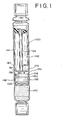
- the shock absorber comprises a hollow cylinder 130 and a piston 132 movably disposed within the cylinder 130.
- the piston 132 is secured on the lower end of a piston rod 134 which has an upper end extending out of the cylinder 130 and attached to a vehicle body chassis (not shown).
- the lower end of the cylinder 130 is attached to a wheel axle (not shown).
- a free piston 136 with annular sealing ring 138 is also movably disposed within the tube to define within the cylinder 130 a pneumatic chamber 140.
- a chamber 142 defined within the cylinder tube 130 and being filled with a working fluid is divided into upper and lower chambers 144 and 146 respectively by the piston 132.
- the piston 132 comprises upper and lower predominately disc-shaped members 148 and 150 respectively formed with horizontally-oriented circular recesses not shown in Fig. 1.
- the upper and lower members are formed with recesses 156, 157 respectively on the circumferences thereof (Fig. 3).
- Vortex passages 164 are defined in the piston 132 such that the outer ends of the vortex passages 164 open toward the recesses 156 and 157 respectively and the inner ends thereof open toward the recesses.
- the inner ends of the vortex passages 164 are directed along the circumference of the recesses.
- the planes having the recesses 152 and 154 face each other.
- the upper and lower members 148 and 150 are secured one another.
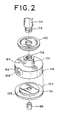
- FIG. 2 to 4 there is illustrated an embodiment of a shock absorber according to the present invention. Though the drawings show only the part of the shock absorber including the piston, it should be understood that the construction of the shock absorber not illustrated herein is the same as shown in Fig. 1.
- the piston comprises an upper member 148 and a lower member 150 engageable with one another.
- the upper member 148 is formed with a circular recess 152 in the lower surface thereof.
- the upper member 148 is formed with a pair of vertically-extending recesses 156 and 157 on its periphery. In the shown embodiment, the recesses 156 and 157 are located in alignment on the diametric line of the upper member 148.
- the recess 156 opens into upper fluid chamber 144 at the upper end thereof and the recess 157 opens into the lower fluid chamber 146 at the lower end thereof.
- the recesses 156 and 157 communicate with the recess 152 via vortex passages 164.
- the vortex passages 164 extend through the upper member 148 and open to the recess 152 at the inner ends and to the recesses 156 or 157 at the outer ends.
- the inner ends of the vortex passages 164 are aligned tangentially to the circle of the recess 152.
- the upper member 148 is further provided with a cylindrical projecting portion 174 with a threaded bore 176 on the upper surface thereof.
- the threaded bore 176 receives a threaded end portion 178 of a piston rod 134 for attaching the piston 132 on to the lower end of the piston rod 134.
- a dish shaped member 180 is mounted on the top of the projecting portion 174 and secured thereon by engagement of the threaded bore 176 and the threaded end portion 178.
- a plurality of narrow passages 184 extend radially through the projecting portion 174 to open toward the threaded bore 176 at the inner ends thereof and into the upper fluid chamber 144 at their outer ends.
- the threaded bore 176 communicates with the recess 152 via a vertical passage 186.
- the lower member 150 is disc-shaped and formed with an annular cut-out 151 along the circumference of the upper plane surface.
- the cut-out 151 is engageable with the lower surface of the upper member 148, as shown in Fig. 3.
- the lower member 150 is also formed with a vertically-extending opening 188 through the central portion thereof.
- a cylindrical pipe 189 is disposed within the opening 188 for reducing the cross-sectional area of the latter.
- the upper and lower members 148 and 150 are assembled together to constitute the piston 132. Upon assembly, the lower member 150 is secured onto the lower surface of the upper member 148 by any suitable means, such as with screws. In the assembled condition, the recess 152 is closed by the lower member 150 to define the vortex chamber 168.
- the piston 132 moves upwards to reduce the volume of the upper fluid chamber 144 and thereby to increase the fluid pressure in the upper fluid chamber 144.
- the volume of the lower fluid. chamber 146 is increased to reduce the fluid pressure in the lower chamber 146. Due to the fluid pressure difference between the upper and lower fluid chamber 144 and 146, the fluid in the upper chamber 144 flows to the lower chamber 146 via the vortex chamber 168 to equalize the fluid pressure. At this case, the fluid in the upper fluid chamber 144 flows into the vortex chamber 168 through the fluid passages 184 and 186, and through the recess 156 and the vortex passage 164.
- the fluid passage 184 has relatively small cross-sectional area, the fluid flow therethrough is limited.
- the fluid flowing into the vortex chamber 168 via the vortex passage 156 is discharged toward the circumference of the vortex chamber to produce the vortex therein.
- the vortex in the vortex chamber 168 also limits the flow of the fluid therethrough. If the piston stroke is relatively small, the resistance against the fluid flow provided by the vortex is insufficient to provide rigidity for the shock absorber. Therefore, against a shock causing a relatively small piston stroke, resistance against the fluid flow in the fluid passages 184 provides most of the absorbing force. Furthermore, the area of the opening 188 reduced by the pipe 189 will serve as an orifice to produce resistance against the fluid flow. As the piston stroke increases, resistance due to the vortex becomes a major part of the absorbing force provided by the shock absorber.
- Fig. 5 shows variation of the absorbing force with respect to the piston speed.
- the absorbing force produced in response to relatively short piston stroke depends mainly on the resistance provided by the orifice effect of the passage 184 and the opening 188. Therefore, the absorbing force against a shock resulting in a relatively small piston stroke can be sufficiently reduced for riding comfort.
- the shock causes relatively great piston stroke, the resistance of the vortex against the fluid flow is sufficiently increased to produce greater absorbing force.
- Figs. 6 and 7 shows a modification of the foregoing second embodiment of the present invention.
- the parts constructed similar to that of the foregoing and having the same function will be represented by the same reference numerals.
- the piston 132 comprises upper and lower members 148 and 150.
- the upper member 148 has a projecting portion 174 on its upper surface.
- the projecting portion 174 is formed with an axially-extending threaded bore 176 with a stepped lower section 190.
- the lower section 190 is in communication with the vertical fluid passage 186.
- the threaded portion 178 of the piston rod 134 engages with the threaded bore 176 for attaching the piston 132 onto the lower end of the piston rod 134.
- the threaded portion 178 of the piston rod 134 and the threaded bore 176 define a fluid flow space 192 with the stepped section 190 of the threaded bore.
- a ball-shaped valve member 194 is disposed within the space 192.
- the stepped section 190 of the threaded bore 176 serves as the valve seat of the valve member 194.
- the lower member 150 is provided with a projecting portion 196 on the lower surface thereof.
- the opening 188 extends through the major portion and the projecting portion 196 of the lower member 150.
- the opening 188 has an enlarged conical lower section 198.
- a retainer plate 200 with a plurality of vertically extending apertures 202 is attached onto the lower end of the projecting portion 196. The retainer plate 200 thus closes the lower end of the through opening 188 but maintains communication between the opening 188 and the lower fluid chamber 146 via the apertures 202.
- a ball-shaped valve member 204 is disposed within the conical lower section 198 of the opening 188. For the valve member 204, the upper end of the conical lower section 198 serves as the valve seat.
- the valve member 194 is urged onto the valve seat 190 to block communication between the upper fluid chamber 144 and the vortex chamber 168, and the fluid in the upper fluid chamber 144 flows into the vortex chamber 168 only via the vortex passages 164.
- the vortex generated in the vortex chamber 168 creates greater resistance against the fluid flow. Since the vortex provides greater resistance than that provided by the fluid passage 184, the absorbing force against this shock becomes considerably greater than that against the shock causing a relatively small piston stroke.
- the fluid flow created by the downward piston motion- and flowing through the opening 188 urges the valve member 204 toward the upper end of the conical lower section 198. If the piston stroke is relatively small, the flow is small. The valve member 204 still permits flow between the lower fluid chamber 146 and the vortex chamber 168. At this time, since the flow into the vortex chamber 168 via the vortex passage 164 is too small to generate the vortex, the resistance against the fluid flow provided by the space between the valve member 204 and the upper end of the lower section 198 provides most of the shock absorbing force.
- the valve member 204 is seated onto the upper end of the lower section 198 to block communication between the lower fluid chamber 146 and the vortex chamber 168, the fluid in the lower fluid chamber 146 flows into the vortex chamber 170 only via the vortex passage 164. In this case, the vortex is generated in the vortex chamber 168 to create resistance against the fluid flow. Since the vortex provides greater resistance than that provided by the orifice effect of the space between the valve member 204 and the upper end of the lower section 198, the absorbing force against this shock becomes considerably greater than that against the shock causing a relatively small piston stroke.
- Fig. 8 shows variation of the absorbing force with respect to the piston speed. As apparent from Fig. 8, the absorbing force produced by the shock absorber of Figs. 6 and 7 depends on not only the piston speed but also the piston stroke.
Landscapes
- Engineering & Computer Science (AREA)
- Mechanical Engineering (AREA)
- General Engineering & Computer Science (AREA)
- Fluid-Damping Devices (AREA)
Claims (5)
Priority Applications (1)
| Application Number | Priority Date | Filing Date | Title |
|---|---|---|---|
| DE8484103628T DE3176912D1 (en) | 1980-08-14 | 1981-08-12 | Shock absorber |
Applications Claiming Priority (6)
| Application Number | Priority Date | Filing Date | Title |
|---|---|---|---|
| JP114598/80 | 1980-08-13 | ||
| JP11559980U JPS61594Y2 (fr) | 1980-08-14 | 1980-08-14 | |
| JP11559880U JPS61593Y2 (fr) | 1980-08-14 | 1980-08-14 | |
| JP115598/80 | 1980-08-14 | ||
| JP115599/80 | 1980-08-14 | ||
| JP55114598A JPS6046596B2 (ja) | 1979-08-20 | 1980-08-19 | スケルチ回路 |
Related Child Applications (3)
| Application Number | Title | Priority Date | Filing Date |
|---|---|---|---|
| EP84103628A Division EP0122532B1 (fr) | 1980-08-13 | 1981-08-12 | Amortisseur de chocs |
| EP84103628A Division-Into EP0122532B1 (fr) | 1980-08-13 | 1981-08-12 | Amortisseur de chocs |
| EP84103628.8 Division-Into | 1981-08-12 |
Publications (3)
| Publication Number | Publication Date |
|---|---|
| EP0045973A2 EP0045973A2 (fr) | 1982-02-17 |
| EP0045973A3 EP0045973A3 (en) | 1983-01-12 |
| EP0045973B1 true EP0045973B1 (fr) | 1985-05-02 |
Family
ID=27312773
Family Applications (2)
| Application Number | Title | Priority Date | Filing Date |
|---|---|---|---|
| EP84103628A Expired EP0122532B1 (fr) | 1980-08-13 | 1981-08-12 | Amortisseur de chocs |
| EP81106291A Expired EP0045973B1 (fr) | 1980-08-13 | 1981-08-12 | Amortisseur de choc |
Family Applications Before (1)
| Application Number | Title | Priority Date | Filing Date |
|---|---|---|---|
| EP84103628A Expired EP0122532B1 (fr) | 1980-08-13 | 1981-08-12 | Amortisseur de chocs |
Country Status (3)
| Country | Link |
|---|---|
| US (1) | US4502575A (fr) |
| EP (2) | EP0122532B1 (fr) |
| DE (1) | DE3170284D1 (fr) |
Families Citing this family (14)
| Publication number | Priority date | Publication date | Assignee | Title |
|---|---|---|---|---|
| JPS58211037A (ja) * | 1982-05-31 | 1983-12-08 | Nissan Motor Co Ltd | シヨツクアブソ−バ |
| JPS6040843A (ja) * | 1983-08-15 | 1985-03-04 | Bridgestone Corp | 防振装置用オリフイス構造 |
| DE3537865A1 (de) * | 1985-10-24 | 1987-05-07 | Lemfoerder Metallwaren Ag | Zweikammer-stuetzlager mit hydraulischer daempfung |
| US4753422A (en) * | 1986-01-30 | 1988-06-28 | Thorn Richard P | Quiet acting low friction decouplers for fluid filled vibration isolators |
| DE3617813A1 (de) * | 1986-05-27 | 1987-12-03 | Freudenberg Carl Fa | Motorlager |
| DE3617812A1 (de) * | 1986-05-27 | 1987-12-03 | Freudenberg Carl Fa | Motorlager |
| US5070972A (en) * | 1990-06-18 | 1991-12-10 | General Motors Corporation | Vortex valving assembly for a hydraulic damper |
| US5810130A (en) * | 1997-03-14 | 1998-09-22 | General Motors Corporation | Suspension damper with rebound cut-off |
| US6209691B1 (en) | 1998-08-04 | 2001-04-03 | General Motors Corporation | Suspension damper with self-aligning rebound cut-off |
| RU2287730C1 (ru) * | 2005-04-25 | 2006-11-20 | Омский танковый инженерный институт | Гидравлический амортизатор |
| KR101798555B1 (ko) * | 2013-11-27 | 2017-11-16 | 주식회사 만도 | 쇽업소버 |
| DE102015008401A1 (de) * | 2015-07-01 | 2017-01-05 | Carl Freudenberg Kg | Trennkolben und Einrohr-Gasdruckstoßdämpfer mit einem solchen Trennkolben |
| JP6709099B2 (ja) * | 2016-04-06 | 2020-06-10 | Kyb株式会社 | 緩衝器 |
| DE102017004478B4 (de) * | 2017-05-10 | 2019-01-31 | Carl Freudenberg Kg | Dichtring, dessen Verwendung und Einrohr-Gasdruckstoßdämpfer, der den Dichtring umfasst |
Family Cites Families (18)
| Publication number | Priority date | Publication date | Assignee | Title |
|---|---|---|---|---|
| US2182581A (en) * | 1937-03-15 | 1939-12-05 | Houde Eng Corp | Hydraulic shock absorber |
| DE697799C (de) * | 1937-05-27 | 1940-10-23 | Ver Deutsche Metallwerke Ag | Fluessigkeitsstossdaempfer |
| US2161811A (en) * | 1937-06-14 | 1939-06-13 | John J Grebe | Shock absorber |
| FR845638A (fr) * | 1937-11-10 | 1939-08-29 | Kronprinz Ag Fu R Metallindust | Dispositif de suspension applicable par exemple aux trains d'atterrissage pour avions |
| BE479002A (fr) * | 1944-10-13 | |||
| US2637414A (en) * | 1951-08-31 | 1953-05-05 | Gabriel Co | Shock absorber |
| FR1242350A (fr) * | 1959-08-19 | 1960-09-30 | Renault | Dispositif amortisseur, notamment pour suspension de véhicule |
| NL299872A (fr) * | 1962-10-30 | 1900-01-01 | ||
| US3672474A (en) * | 1970-02-16 | 1972-06-27 | Bendix Corp | Fluid flow device for a shock absorber |
| US3804216A (en) * | 1970-12-29 | 1974-04-16 | Tokico Ltd | Shock absorber and suspension mechanism |
| DE2727244C2 (de) * | 1976-06-30 | 1990-06-21 | Automobiles Peugeot, 75116 Paris | Gummifeder mit Flüssigkeitsfüllung |
| DE2833776C2 (de) * | 1977-03-23 | 1983-12-15 | Boge Gmbh, 5208 Eitorf | Zweikammer-Motorlager |
| FR2425585A1 (fr) * | 1978-05-11 | 1979-12-07 | Peugeot | Perfectionnement aux amortisseurs hydrauliques telescopiques |
| CA1127191A (fr) * | 1978-10-13 | 1982-07-06 | L. Dale Coad | Amortisseur hydraulique |
| GB2044882B (en) * | 1979-02-27 | 1983-10-26 | Nissan Motor | Hydraulic shock absorber with vortex valve |
| US4335644A (en) * | 1979-09-14 | 1982-06-22 | Goes Michael J | Fluidic recoil buffer for small arms |
| DE2950888A1 (de) * | 1979-12-18 | 1981-06-25 | Stabilus Gmbh | Daempfkolben fuer pneumatische, hydraulische und hydropneumatische aggregate |
| JPS5733240A (en) * | 1980-08-07 | 1982-02-23 | Nissan Motor Co Ltd | Shock absorber |
-
1981
- 1981-07-23 US US06/285,999 patent/US4502575A/en not_active Expired - Lifetime
- 1981-08-12 EP EP84103628A patent/EP0122532B1/fr not_active Expired
- 1981-08-12 EP EP81106291A patent/EP0045973B1/fr not_active Expired
- 1981-08-12 DE DE8181106291T patent/DE3170284D1/de not_active Expired
Also Published As
| Publication number | Publication date |
|---|---|
| EP0045973A3 (en) | 1983-01-12 |
| US4502575A (en) | 1985-03-05 |
| EP0122532B1 (fr) | 1988-10-19 |
| EP0045973A2 (fr) | 1982-02-17 |
| EP0122532A3 (en) | 1986-06-11 |
| EP0122532A2 (fr) | 1984-10-24 |
| DE3170284D1 (en) | 1985-06-05 |
Similar Documents
| Publication | Publication Date | Title |
|---|---|---|
| US4964493A (en) | Shock absorber with variable damping characteristics depending upon stroke speed | |
| US4905799A (en) | Shock absorber | |
| CA1058643A (fr) | Amortisseur | |
| US5316113A (en) | Hydraulic shock absorber | |
| US6213263B1 (en) | Oil damper system | |
| KR101454050B1 (ko) | 베이스 라인 밸브형의 계속적으로 변화가능한 밸브를 갖는 충격 완충기 | |
| US4203507A (en) | Shock absorber | |
| US4502575A (en) | Shock absorber | |
| US20030106753A1 (en) | Damping force control type hydraulic shock absorber | |
| GB2266573A (en) | Variable damping force shock absorber | |
| EP0317327A2 (fr) | Amortisseur de chocs hydraulique | |
| US3677561A (en) | Adjustable shock absorber assemblies | |
| EP0161430A2 (fr) | Amortisseur de choc | |
| JP3516889B2 (ja) | 二段型ショックアブソーバ | |
| EP0477326B1 (fr) | Ensemble amortisseur reglable | |
| JPH05209643A (ja) | ピストン組立体 | |
| US4515252A (en) | Piston stroke responsive vortex-flow shock absorber | |
| US5226512A (en) | Variable damping force shock absorber with variable orifice for adjusting damping characteristics | |
| US4775038A (en) | Spring loaded piston seal and valving component for shock absorbers, Macpherson struts and the like | |
| US6230858B1 (en) | Internally slotted orifice disc for low speed control in automotive dampers | |
| EP1110768B1 (fr) | Dispositif de suspension de véhicule | |
| US5193655A (en) | Variable damping force shock absorber with feature of linear and wide range damping force variation depending upon piston stroke speed | |
| US4407397A (en) | Shock absorber with pressure-relief mechanism | |
| US5769190A (en) | Continuous controlled restriction valve for a shock absorber | |
| EP0336758A2 (fr) | Amortisseur de chocs ayant des caractéristiques d'amortissement variables selon la vitesse de déplacement du piston |
Legal Events
| Date | Code | Title | Description |
|---|---|---|---|
| PUAI | Public reference made under article 153(3) epc to a published international application that has entered the european phase |
Free format text: ORIGINAL CODE: 0009012 |
|
| AK | Designated contracting states |
Designated state(s): DE FR GB |
|
| PUAL | Search report despatched |
Free format text: ORIGINAL CODE: 0009013 |
|
| AK | Designated contracting states |
Designated state(s): DE FR GB |
|
| 17P | Request for examination filed |
Effective date: 19821207 |
|
| GRAA | (expected) grant |
Free format text: ORIGINAL CODE: 0009210 |
|
| AK | Designated contracting states |
Designated state(s): DE FR GB |
|
| REF | Corresponds to: |
Ref document number: 3170284 Country of ref document: DE Date of ref document: 19850605 |
|
| RAP2 | Party data changed (patent owner data changed or rights of a patent transferred) |
Owner name: NISSAN MOTOR CO., LTD. |
|
| ET | Fr: translation filed | ||
| PLBE | No opposition filed within time limit |
Free format text: ORIGINAL CODE: 0009261 |
|
| STAA | Information on the status of an ep patent application or granted ep patent |
Free format text: STATUS: NO OPPOSITION FILED WITHIN TIME LIMIT |
|
| 26N | No opposition filed | ||
| PG25 | Lapsed in a contracting state [announced via postgrant information from national office to epo] |
Ref country code: FR Free format text: LAPSE BECAUSE OF NON-PAYMENT OF DUE FEES Effective date: 19880429 |
|
| PG25 | Lapsed in a contracting state [announced via postgrant information from national office to epo] |
Ref country code: DE Effective date: 19880503 |
|
| GBPC | Gb: european patent ceased through non-payment of renewal fee | ||
| REG | Reference to a national code |
Ref country code: FR Ref legal event code: ST |
|
| PG25 | Lapsed in a contracting state [announced via postgrant information from national office to epo] |
Ref country code: GB Free format text: LAPSE BECAUSE OF NON-PAYMENT OF DUE FEES Effective date: 19881118 |