EP0046343A2 - Verfahren und Gerät zur numerischen Steuerung - Google Patents
Verfahren und Gerät zur numerischen Steuerung Download PDFInfo
- Publication number
- EP0046343A2 EP0046343A2 EP81303367A EP81303367A EP0046343A2 EP 0046343 A2 EP0046343 A2 EP 0046343A2 EP 81303367 A EP81303367 A EP 81303367A EP 81303367 A EP81303367 A EP 81303367A EP 0046343 A2 EP0046343 A2 EP 0046343A2
- Authority
- EP
- European Patent Office
- Prior art keywords
- tool
- current position
- command
- workpiece
- another
- Prior art date
- Legal status (The legal status is an assumption and is not a legal conclusion. Google has not performed a legal analysis and makes no representation as to the accuracy of the status listed.)
- Withdrawn
Links
Images


Classifications
-
- G—PHYSICS
- G05—CONTROLLING; REGULATING
- G05B—CONTROL OR REGULATING SYSTEMS IN GENERAL; FUNCTIONAL ELEMENTS OF SUCH SYSTEMS; MONITORING OR TESTING ARRANGEMENTS FOR SUCH SYSTEMS OR ELEMENTS
- G05B19/00—Program-control systems
- G05B19/02—Program-control systems electric
- G05B19/18—Numerical control [NC], i.e. automatically operating machines, in particular machine tools, e.g. in a manufacturing environment, so as to execute positioning, movement or co-ordinated operations by means of program data in numerical form
- G05B19/416—Numerical control [NC], i.e. automatically operating machines, in particular machine tools, e.g. in a manufacturing environment, so as to execute positioning, movement or co-ordinated operations by means of program data in numerical form characterised by control of velocity, acceleration or deceleration
- G05B19/4166—Controlling feed or in-feed
-
- G—PHYSICS
- G05—CONTROLLING; REGULATING
- G05B—CONTROL OR REGULATING SYSTEMS IN GENERAL; FUNCTIONAL ELEMENTS OF SUCH SYSTEMS; MONITORING OR TESTING ARRANGEMENTS FOR SUCH SYSTEMS OR ELEMENTS
- G05B2219/00—Program-control systems
- G05B2219/30—Nc systems
- G05B2219/50—Machine tool, machine tool null till machine tool work handling
- G05B2219/50008—Multiple, multi tool head, parallel machining
Definitions
- This invention relates to a numerical control method and appratus and more particularly to a numerical control method and apparatus for a machine tool of the type wherein a plurality of tools, which are moved in unison and which have a fixed positional relationship with respect to one another, are moved on the basis of absolute commands, a workpiece being machined successively by selected ones of the tools.
- a machine tool such as a lathe is provided with a plurality of tools that are firmly mounted on a tool rest. To execute a machining operation, desired ones of these tools are selected depending upon whether rough or fine cutting is required. Turning and drilling tools and the like may also be selected as the machining operation progresses.
- a machining program tape for a machine of the described type ordinarily includes a mixture of position commands for the various tools. It is advantageous in terms of programming if the position commands are expressed as absolute commands, since the coordinates of the position to which a tool is to be moved need merely be commanded in the form of a position, a very simple operation for the programmer. To make this possible, the numerical control device is adapted to internally compute an incremental value, namely the difference between the current position of the tool and the position to which the tool is to be moved, and to execute a pulse distributing operation on the basis of the incremental value. In other words, the numerical control device must constantly be aware of the current position of the tool when an absolute command is issued.
- the following three methods have been proposed as numerical control methods for controlling a machine tool of the type having a plurality of tools whose coordinates differ from one another, wherein desired tools are selected as machining progresses in order to subject a workpiece to a number of machining operations such as turning and the like.
- the three methods are:
- the method (1) Since all of the tools move in unison, the method (1) is disadvantageous because the current positions of each of the plurality of tools must be computed and stored in the registers whenever the tools are moved. This requires considerable time for computations, leading to a decline in machining efficiency. With the method (2) there is the requirement for the restoration to the reference point each time a tool is changed. This lengthens machining time and seriously lowers machining efficiency. The method (3) requires that the operator manually calculate and enter the current position of the new tool whenever tools are changed. This is a time- consuming and troublesome operation.
- a method of numerically controlling at least two tools which are arranged to move in unison while maintaining a constant positional relationship with respect to one another, the tools being moved relative to a workpiece on the basis of absolute commands to subject the workpiece to a prescribed machining operation, which method comprises the steps of:
- an apparatus for numerically controlling at least two tools which are arranged to move in unison while maintaining a constant positional relationship with respect to one another, when the apparatus is in use the tools being moved relative to a workpiece on the basis of absolute commands to subject the workpiece to a presecribed machining operation, which apparatus comprises:
- an apparatus for use in numerically controlling at least two tools which are arranged to move in unison while maintaining a constant positional relationship with respect to one another, the tools being movable relative to a workpiece on the basis of absolute commands to subject the workpiece to a prescribed machining operation which apparatus comprises:
- An example of the present invention may provide a numerical control method and apparatus for application to a numerical control device for a machine tool which employs a plurality of tools selectively to machine a workpiece, which method and apparatus requires only a current position register for one tool without any decline in machining efficiency. It may further provide a numerical control method and apparatus which can decrease the computing time of the current position and allow an NC unit to have enough time for performing various numerical control treatments.
- a workpiece WK having the shape of a round bar is fixed rigidly by means of a chuck provided on a lathe, neither the chuck nor the lathe being shown in the drawings.
- Fixedly secured to a tool holder TL on either side of the workpiece WK are two tools TL 1 , TL 2 . Since the tools TL 1 , TL 2 are fixed to the same tool holder TL, moving the tool holder to bring one tool into use causes the other tool to follow the movement of the first, so that a fixed positional relationship is maintained between the two tools at all times.
- the spacing between the noses of the two tools when projected on the X-axis and when projected on the Z-axis is constant. Accordingly, letting the coordinates (X 1 , Z 1 ), (X 2 , Z 2 ) represent the tool nose positions of the respective tools TL 1 , TL 2 permits us to write
- only one current position register is provided, and the arrangement is such that when machining by one tool, say the tool TL 1 , is completed, the operations are performed before machining by the tool TL 2 starts.
- the result of these operations provides the current position (X 2 , Z 2 ) of the nose of tool TL 2' It should be noted that the current position (X 1 , Z 1 ) of the tool TL 1 /is stored in the current position register as long as tool TL 1 is the active tool.
- FIG. 2 The views of Fig. 2 are illustrative of a numeri- which is in accordance with cal control method / the present invention.
- Fig. 2(A) shows the positional relationship between the workpiece WK and the tools TL 1 , TL 2 as well as the contents of the current position register, immediately after coordinates have been set.
- Fig. 2(B) is a similar view following positioning at a machining position (point A).
- Fig. 2(C) is a similar view following a retraction operation, Fig. 2(D) is a similar view following setting of coordinates, and
- Fig. 2(E) is a similar view following positioning at the machining position (point A).
- FIG. 3 is a table showing the relationship among command data in each step of a machining program stored on a recording medium such as an NC tape, the content of the current position register following the execution of the program steps, and the current positions of the tools TL 1 , TL 2 .
- XR, ZR denote current position register sections for the X- and Z-axes, these register sections constituting a single register unit.
- the distance between the nose of the tool TL 1 and the nose of the tool TL 2 is 10 along the X-axis, and 100 along the Z-axis, these distances being constant as mentioned above.
- N i (N 1 , N 2 ...) in the machining program data column denotes a sequence number
- G50 denotes a preparatory function command for setting coordinates
- X 0...0 and Z 0...0 denote absolute values along the X- and Z-axes, respectively
- U 0...0, W 0...0 denote incremental values along the X-and Z-axes, respectively.
- the command data presets the current position registers XR, ZR to the numerical values which follow the letters X and Z, threby establishing the coordinates.
- the command data presets the current position registers XR, ZR to the values [X] +U, [Z] + W, thereby establishing the coordinates.
- [X] and [Z] are the contents of the X-axis and Z-axis registers, respectively.
- the command data at sequence number N 1 of the machining program is now read in the numerical control device, whereupon the values 200 and 400 are preset in the current position registers XR, ZR, respectively.
- the above operation sets the coordinates (X 1 , Z 1 ) of the tool TL 1 in the respective current position registers XR, ZR.
- the tool TL 1 is moved toward the machining point A (by moving the tool holder) in accordance with the command data at sequence number N 2 , until it is positioned at the point A, as shown in Fig. 2(B).
- the workpiece WK is now machined by the tool TL 1 under the control of the numerical control device, this operation not being described here.
- the tool holder is retracted in accordance with the command data at sequence number N 3 .
- the results of the operations are stored in the shift registers XR, ZR, as shown in Fig. 2(D).
- the coordinates X 2 , Z 2 of tool TL 2 are stored in the current position registers XR, ZR.
- the command data at sequence number N 5 is read in next..
- the tool TL 2 being carried by the tool holder, makes its approach to the machining point A and stops when positioned at point A, as depicted in Fig. 5(E).
- the command G50 U 10 W-100 * for setting coordinates need only be included in the machining program.
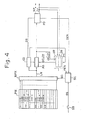
- Fig. 4 is a block diagram of a numerical control according to device for practicing a method / the present invention.
- a program memory PM sequentially stores the machining data, shown in Fig. 3, starting from the sequence number N 1 . This is accomplished by means of a tape reader which reads in the machining data from a paper tape, neither the tape reader nor the paper tape being illustrated in the drawings.
- a multiplexer MPX selects and delivers predetermined machining data from the program memory PM under the control of a sequence control circuit SC.
- the sequence control circuit SC includes a counter whose content is advanced by, say, a preset end signal (a signal indicating the completion of a presetting operation) and a pulse distribution end signal (a signal indicating the completion of a pulse distribution operation), the arrangement being such that command data is delivered from the program memory PM through the multiplexer MPX in the order of the sequence numbers, on the basis of the value of the count within the counter.
- the sequence controller SC is actuated by a start button SB.
- a command discrimination circuit CD is adapted to produce a preset signal PS that presets the result of an operation, perfcrmed by an adder-subtractor AS, in the current position registers XR, ZR when the command data is the preparatory fucntion command G50 for setting coordinates, and to produce a distribution start signal DS when the command data is a position command.
- the adder-subtractor circuit AS performs a predetermined arithmetic operation in accordance with whether an input received from the multiplexer MPX is an incremental command or an absolute command.
- the adder-subtractor circuit AS performs the operations to compute an incremental value which is delivered to a pulse distributor which will be described below.
- the adder-subtractor circuit AS When the command is an incremental command for setting coordinates (the incremental command being expressed by the numerical values which follow the letters U, W), the adder-subtractor circuit AS performs the operations with the results of the operations (indicating the current position of the other tool) being preset in the current position registers XR, ZR.
- the pulse distributor denoted at PD, is of the well-known type and is adapted to perform a pulse distribution operation to produce pulses XP, ZP that are sent to X-axis and Z-axis servo control systems .(not shown), the servo control systems responding by moving the tool holder along the X- and Z-axis.
- Figs. 2 through 4 desoribe system operation.
- the start button sa is depressed under the conditions shown in Fig. 2 (A). This results in the generation of a start signal SS which is applied to the sequence controller SC to start the controller, the latter responding by sending a gate signal GS to the multiplexer MPX.
- the latter on the basis of the gate signal, supplies a line LN with the command data at the sequence number N 1 .
- This data is the absolute data for setting coordinates and is discriminated as such by the command discrimination circuit CD which consequently delivers the preset signal PS to the current position registers XR, ZR.
- the adder-subtractor circuit AS is performing the operations given in (1) above, (where the contents [X], [Z] of the current position registers XR, ZR are initially both zero).
- the results of these operations namely [X'], [Z'], are preset in the position registers XR, ZR by the preset signal PS.
- the current position register unit formed by registers XR, ZR issues a preset end signal PEN which increments, by one count, the counter contained within the sequence control circuit SC.
- the counter is not shown in the drawings.
- the result of this-operation is that the multiplexer MPX now sends out on line LN the command data at sequence number N 2 .
- the adder-subtractor circuit AS Since the command data at sequence number N 2 is the absolute position command, the adder-subtractor circuit AS immediately performs the operations given-in (1) above and delivers the results, which are incremental values, to the pulse distributor PD. Meanwhile, the fact that the data is a position command is discriminated by the command discrimination circuit CD which sends a pulse distribution start signal DS to the pulse discriminator circuit PD. The latter circuit responds by performing a pulse distribution operation on the basis of the abovementioned incremental values. Thus, distributed pulses XP, ZP are delivered successively for movement in the X- and Z-directions.
- the pulses XP, ZP are applied to the servo systems (not shown) to drive the tool holder, and to the current position registers XR, ZR which are incremented by +1 or decremented by -1 by each arriving pulse, in accordance with the direction of tool holder movement.
- the current position registers XR, ZR always store the current position of one of the tools.
- the nose of tool TL 1 will be at the machining position A, as shown in Fig. 2(A), and the current position of the tool TL 1 (actually the position of the tool nose, or the coordinates of the point A) will have been stored in the current position registers XR, ZR.
- the pulse distributor issues the distribution end pulse END after completing the pulse distribution operation, the latter pulse incrementing, by +1, the content of the counter contained in the sequence control circuit SC.
- the multiplexer MPX now supplies the line LN with the command data at sequence number N 3 .
- the command data at sequence number N 3 is an absolute position command, as in the immediately preceding case just described, so the circuitry operates in the same fashion.
- the pulse distributor circuit PD issues a distribution end pulse DEN upon completion of the pulse distribution, and the content of the counter in the sequence control circuit SC is advanced by +1.
- the multiplexer delivers the command data at the next sequence number, which is N 4 . Since this data is an incremental command for setting coordinates, the command discrimination circuit CD issues the preset signal FS and sends an add signal to the adder-subtracter circuit AS, causing the latter to execute the operations given in (2) above.
- the result of these arithmetic operations is the current position of the tool TL 2 , that is, the current position of the nose of the tool. This position is preset in the current position registers XR, ZR by the.preset signal PS.
- the adder-subtractor circuit AS issues the preset end signal PEN following the preset operation, the signal advancing the counter in the sequence control circuit SC by a further step, so that the multiplexer MPX now delivers the command data at sequence number N 5 . Machining progresses as the foregoing steps are repeated. It should be noted that the current position of the tool TL 2 will be stored in the current position registers XR, ZR until a command for setting coordinates appears in the machining program.
- the present invention is not limited to such an arrangement; a microprocessor can be substituted for the sequence control circuit. Furthermore, the present invention is not limited to an arrangement having only two tools; three or more tools may be provided. Finally, the changes in the coordinate values U, W need not necessarily be entered by the command data which follows the G50 command, as described above.
- the tool distances can be stored in memory separately in advance.
- a method and apparatus for numerically controlling at least two tools which are arranged to move in unison while maintaining a constant positional relationship with respect to one another, the tools being moved relative to a workpiece on the basis of absolute commands to subject the workpiece to a prescribed machining operation.
- a single current position register (XR, ZR) consisting of one section (XR) for storing X coordinates and one section (ZR) for storing Z coordinates, is provided to store the current position of a first tool.
- arithmetic means responsive to a command for setting coordinates, for computing the current position of a second tool which is to be used next, as well as pulse distribution means (PD).
- the method includes the steps of storing the position of the first tool in the current position register (XR, ZR) prior to machining the workpiece with that tool, moving the first tool to machine the workpiece on the basis of the current position and an absolute command, computing the current position of the second tool by the arithmetic means (AS) in response to the command for setting coordinates in effectirx a changeover from the first tool to the second tool, storing the computed current position in the current position register (XR, ZR), and moving the second tool to machine the workpiece on the basis of the content of the current position register (XR, ZR) and an absolute command.
- AS arithmetic means
Landscapes
- Engineering & Computer Science (AREA)
- Human Computer Interaction (AREA)
- Manufacturing & Machinery (AREA)
- Physics & Mathematics (AREA)
- General Physics & Mathematics (AREA)
- Automation & Control Theory (AREA)
- Numerical Control (AREA)
- Control Of Position Or Direction (AREA)
Applications Claiming Priority (2)
| Application Number | Priority Date | Filing Date | Title |
|---|---|---|---|
| JP10152180A JPS5727306A (en) | 1980-07-24 | 1980-07-24 | Numerical control system |
| JP101521/80 | 1980-07-24 |
Publications (2)
| Publication Number | Publication Date |
|---|---|
| EP0046343A2 true EP0046343A2 (de) | 1982-02-24 |
| EP0046343A3 EP0046343A3 (de) | 1982-03-10 |
Family
ID=14302801
Family Applications (1)
| Application Number | Title | Priority Date | Filing Date |
|---|---|---|---|
| EP81303367A Withdrawn EP0046343A3 (de) | 1980-07-24 | 1981-07-23 | Verfahren und Gerät zur numerischen Steuerung |
Country Status (4)
| Country | Link |
|---|---|
| US (1) | US4424569A (de) |
| EP (1) | EP0046343A3 (de) |
| JP (1) | JPS5727306A (de) |
| KR (1) | KR850000328B1 (de) |
Cited By (1)
| Publication number | Priority date | Publication date | Assignee | Title |
|---|---|---|---|---|
| DE3627658A1 (de) * | 1985-08-15 | 1987-02-26 | Mitsubishi Electric Corp | Numerische steuervorrichtung fuer zwei werkzeuge |
Families Citing this family (23)
| Publication number | Priority date | Publication date | Assignee | Title |
|---|---|---|---|---|
| JPS5760407A (en) * | 1980-09-30 | 1982-04-12 | Fanuc Ltd | Numerical control system |
| JPS57111607A (en) * | 1980-12-26 | 1982-07-12 | Fanuc Ltd | Numerical control device |
| JPS58132460A (ja) * | 1982-01-29 | 1983-08-06 | Toyoda Mach Works Ltd | アンギユラ研削盤用数値制御装置 |
| JPS58155150A (ja) * | 1982-03-11 | 1983-09-14 | Yamazaki Mazak Corp | 4軸数値制御旋盤 |
| JPS58155101A (ja) * | 1982-03-11 | 1983-09-14 | Yamazaki Mazak Corp | 4軸数値制御旋盤 |
| JPS5942248A (ja) * | 1982-09-03 | 1984-03-08 | Mitsubishi Electric Corp | 数値制御加工方式 |
| JPS5976701A (ja) * | 1982-10-25 | 1984-05-01 | Fanuc Ltd | 櫛刃型旋盤の制御方法 |
| JPS59152042A (ja) * | 1983-02-16 | 1984-08-30 | Mitsubishi Electric Corp | 数値制御加工方式 |
| JPS6151203A (ja) * | 1984-08-18 | 1986-03-13 | Fanuc Ltd | 数値制御方式 |
| US4672549A (en) * | 1984-11-01 | 1987-06-09 | Saxton Richard E | Coil spring forming machine |
| DE3504013A1 (de) * | 1985-02-06 | 1986-08-07 | Jagenberg AG, 4000 Düsseldorf | Positioniereinrichtung fuer mehrere, nebeneinander und auf gegenseitigen abstand verfahrbare einheiten |
| JPS6249503A (ja) * | 1985-08-29 | 1987-03-04 | Mitsubishi Electric Corp | 数値制御装置 |
| JPS62199343A (ja) * | 1986-02-25 | 1987-09-03 | Fanuc Ltd | 同時4軸旋盤の加工時間表示方法 |
| JPS62236650A (ja) * | 1986-04-01 | 1987-10-16 | Fanuc Ltd | 4軸旋盤のncプログラム作成方法 |
| JPS62237504A (ja) * | 1986-04-08 | 1987-10-17 | Fanuc Ltd | 数値制御装置 |
| JPH01193146A (ja) * | 1988-01-29 | 1989-08-03 | Mitsubishi Electric Corp | 数値制御装置 |
| US5163009A (en) * | 1988-05-09 | 1992-11-10 | Seibu Electric Machinery Co., Ltd. | Method of machining cylindrical workpieces by using a bi-spindle numerically controlled machine tool |
| US5040342A (en) * | 1988-10-11 | 1991-08-20 | Ppg Industries, Inc. | Method and apparatus for processing glass sheets |
| US5287285A (en) * | 1991-05-24 | 1994-02-15 | Industrial Technology Research Institute | Electronic multi-shaft absolute position detecting device |
| US5590454A (en) * | 1994-12-21 | 1997-01-07 | Richardson; Kendrick E. | Method and apparatus for producing parts by layered subtractive machine tool techniques |
| US7346973B2 (en) * | 2002-09-09 | 2008-03-25 | Nissin Manufacturing Co., Ltd. | Processing cell of automatic machining system and automatic honing system |
| US7040196B2 (en) * | 2003-01-24 | 2006-05-09 | Automated Solutions | Assembly machine with spatial positioning control |
| DE102012006124A1 (de) * | 2012-03-20 | 2013-09-26 | Michael Weinig Ag | Verfahren zur Erzeugung von Strukturen oder Konturen an einem Werkstück sowie eine Kehlmaschine |
Family Cites Families (9)
| Publication number | Priority date | Publication date | Assignee | Title |
|---|---|---|---|---|
| US3825731A (en) | 1970-01-30 | 1974-07-23 | Fujitsu Ltd | Numerical control system |
| JPS5417115B2 (de) | 1971-09-09 | 1979-06-27 | ||
| IT942654B (it) | 1971-09-30 | 1973-04-02 | Olivetti & Co Spa | Sistema di controllo numerico per il comando simultaneo di piu uten sili o assi di una o piu macchine utensili |
| US3818301A (en) | 1973-05-03 | 1974-06-18 | Warner Swasey Co | Multiplexed machine control apparatus |
| JPS5021384A (de) * | 1973-06-29 | 1975-03-06 | ||
| JPS5110284A (en) | 1974-07-15 | 1976-01-27 | Oki Electric Ind Co Ltd | Suchiseigyosochino seigyohoshiki |
| NL7511705A (nl) | 1975-10-06 | 1977-04-12 | Philips Nv | Numerieke besturing voor een multigereedschap- machine. |
| JPS53114580A (en) * | 1977-03-17 | 1978-10-06 | Fanuc Ltd | Tool selecting system of numerical control machine tool |
| US4257103A (en) | 1977-11-16 | 1981-03-17 | Heian Iron Works, Ltd. | Apparatus for controlling position of a plurality of machining shafts each including a machine tool fitted thereto |
-
1980
- 1980-07-24 JP JP10152180A patent/JPS5727306A/ja active Pending
-
1981
- 1981-07-14 US US06/283,349 patent/US4424569A/en not_active Expired - Fee Related
- 1981-07-22 KR KR1019810002654A patent/KR850000328B1/ko not_active Expired
- 1981-07-23 EP EP81303367A patent/EP0046343A3/de not_active Withdrawn
Cited By (1)
| Publication number | Priority date | Publication date | Assignee | Title |
|---|---|---|---|---|
| DE3627658A1 (de) * | 1985-08-15 | 1987-02-26 | Mitsubishi Electric Corp | Numerische steuervorrichtung fuer zwei werkzeuge |
Also Published As
| Publication number | Publication date |
|---|---|
| KR830006972A (ko) | 1983-10-12 |
| US4424569A (en) | 1984-01-03 |
| JPS5727306A (en) | 1982-02-13 |
| EP0046343A3 (de) | 1982-03-10 |
| KR850000328B1 (ko) | 1985-03-20 |
Similar Documents
| Publication | Publication Date | Title |
|---|---|---|
| EP0046343A2 (de) | Verfahren und Gerät zur numerischen Steuerung | |
| US5150305A (en) | Numerical control system providing graphic machining simulation | |
| US4604705A (en) | Numerical control machining method and system therefor | |
| US4776247A (en) | Numerical control system | |
| EP0122943B1 (de) | Kontrollmethode für drehbank | |
| US5315503A (en) | Numerical control apparatus having a teaching function and a method of teaching a machining program thereby | |
| JPS6363921B2 (de) | ||
| US4700313A (en) | Plural turret system with display of permitted and non-permitted simultaneous machining operations | |
| US4513380A (en) | Method of tool recovery in threadcutting apparatus | |
| EP0103428B1 (de) | Programmiergerät für eine numerische Steuerung | |
| EP0164686B1 (de) | Wechselwirkende numerische Steuerung für eine Werkzeugmaschine | |
| EP0104542B1 (de) | Numerisch gesteuerte Bearbeitungsmethode | |
| GB1599585A (en) | Numerically-controlled machine tool system | |
| US4766546A (en) | Numerically controlled apparatus including functions of synchronous-simultaneous transaction and independent-simultaneous translation | |
| US3731175A (en) | Servo system for velocity and position control | |
| EP0328665B1 (de) | Numerische steuerung | |
| EP0123696A1 (de) | Verfahren zur herstellung eines numerisch gesteuerten programms | |
| JP4310018B2 (ja) | Nc工作機械における工具の位置補正方法 | |
| JPH06262403A (ja) | 工作機械における移動体の位置制御装置 | |
| JP2606714B2 (ja) | 数値制御装置 | |
| KR830001478B1 (ko) | 수치 제어공작기계에 있어서 공구선택 방법 | |
| EP0038391B1 (de) | Kopiersteuerungsausrüstung | |
| JPH0649263B2 (ja) | ワ−ク座標系設定制御方法 | |
| JPS61173845A (ja) | 旋盤における刃先位置の測定制御方法 | |
| JPH01300306A (ja) | 自動プログラミング方法 |
Legal Events
| Date | Code | Title | Description |
|---|---|---|---|
| PUAI | Public reference made under article 153(3) epc to a published international application that has entered the european phase |
Free format text: ORIGINAL CODE: 0009012 |
|
| PUAL | Search report despatched |
Free format text: ORIGINAL CODE: 0009013 |
|
| AK | Designated contracting states |
Designated state(s): DE FR GB |
|
| AK | Designated contracting states |
Designated state(s): DE FR GB |
|
| RBV | Designated contracting states (corrected) |
Designated state(s): DE FR GB |
|
| 17P | Request for examination filed |
Effective date: 19820812 |
|
| RAP1 | Party data changed (applicant data changed or rights of an application transferred) |
Owner name: FANUC LIMITED |
|
| RAP1 | Party data changed (applicant data changed or rights of an application transferred) |
Owner name: FANUC LTD |
|
| STAA | Information on the status of an ep patent application or granted ep patent |
Free format text: STATUS: THE APPLICATION IS DEEMED TO BE WITHDRAWN |
|
| 18D | Application deemed to be withdrawn |
Effective date: 19850807 |
|
| RIN1 | Information on inventor provided before grant (corrected) |
Inventor name: YOSHIMASA, KAGAWA Inventor name: RYOJI, IMAZEKI Inventor name: HIROOMI, FUKUYAMA |