EP0046480A2 - Dispositif de verrouillage pour boutons de commande des appareils de commutation électriques - Google Patents
Dispositif de verrouillage pour boutons de commande des appareils de commutation électriques Download PDFInfo
- Publication number
- EP0046480A2 EP0046480A2 EP81102807A EP81102807A EP0046480A2 EP 0046480 A2 EP0046480 A2 EP 0046480A2 EP 81102807 A EP81102807 A EP 81102807A EP 81102807 A EP81102807 A EP 81102807A EP 0046480 A2 EP0046480 A2 EP 0046480A2
- Authority
- EP
- European Patent Office
- Prior art keywords
- slide
- switch button
- bolt
- locked
- locking device
- Prior art date
- Legal status (The legal status is an assumption and is not a legal conclusion. Google has not performed a legal analysis and makes no representation as to the accuracy of the status listed.)
- Granted
Links
- 230000006835 compression Effects 0.000 claims abstract description 13
- 238000007906 compression Methods 0.000 claims abstract description 13
- 230000000694 effects Effects 0.000 claims description 2
- 238000006073 displacement reaction Methods 0.000 description 2
- 238000004519 manufacturing process Methods 0.000 description 2
- FGRBYDKOBBBPOI-UHFFFAOYSA-N 10,10-dioxo-2-[4-(N-phenylanilino)phenyl]thioxanthen-9-one Chemical compound O=C1c2ccccc2S(=O)(=O)c2ccc(cc12)-c1ccc(cc1)N(c1ccccc1)c1ccccc1 FGRBYDKOBBBPOI-UHFFFAOYSA-N 0.000 description 1
- 238000010276 construction Methods 0.000 description 1
- 238000009434 installation Methods 0.000 description 1
- 238000000034 method Methods 0.000 description 1
- 230000000284 resting effect Effects 0.000 description 1
Images

Classifications
-
- H—ELECTRICITY
- H01—ELECTRIC ELEMENTS
- H01H—ELECTRIC SWITCHES; RELAYS; SELECTORS; EMERGENCY PROTECTIVE DEVICES
- H01H9/00—Details of switching devices, not covered by groups H01H1/00 - H01H7/00
- H01H9/20—Interlocking, locking, or latching mechanisms
- H01H9/26—Interlocking, locking, or latching mechanisms for interlocking two or more switches
Definitions
- the invention relates to a locking device for buttons of electrical switching devices.
- the invention relates to all devices whose switching can be actuated either by a continuous signal or by a pulse.
- a device is e.g. a contactor, which has buttons that act on contact devices in a known manner, whereby a magnet system attracts.
- a contactor is activated when the coil of the magnet system receives voltage. In principle, it can be kept in operation in two ways: firstly by a continuous signal, for example by closing a switch, so that the contactor is actuated as long as the signal continues; secondly by a signal in the form of a short pulse, a few tenths of a second of the pulse being sufficient so that the contactor, once it has been actuated, is self-holding by its own switching means. In this The contactor remains activated even if the switch element or the switch, which is usually designed as a push-button switch with switch buttons, is released.
- the contactor is switched off as soon as there is no more voltage on the coil, either because the control switch is switched off or opened, or because the circuit is interrupted with a second push-button switch or because the circuit is interrupted for another reason , e.g. due to failure of the food source.
- the invention has for its object to provide a locking device that offers a choice between the control by permanent contact and the control by pulse contact.
- a slide is guided in a longitudinally displaceable manner, which is designed in such a way and interacts with the switching buttons that either either at least one switching button can be locked in the operating position to achieve control by permanent contact, or all switching buttons can be unlocked to achieve control by pulse contact.
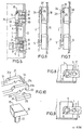
- the housing cover 12 for a non-illustrated electrical switching device is designed to be open on one side in a box-like manner, specifically the housing cover opens to the rear, that is to say to the electrical switching device to be covered, and can, for example, by means of two screw bolts according to FIG. 1 be connected to the relevant switching device.
- a slide 1 is guided in a longitudinally displaceable manner.
- two elongated holes 3 are provided for this guide in the slide 1, through which pins 2 protrude, which are mounted in the housing cover, as particularly illustrated in FIGS. 3 and 5.
- two externally operable and accessible switch buttons 9 and 18 are provided on the housing cover 12, the one switch button 9 being lockable and the other switch button 18 not being lockable.
- the switch button 9 to be locked has a bolt 6 and a compression spring 10 on the back.
- the bolt 6 has an extended piece 7 after the end remote from the switch button 9, while the other bolt part 8 in between is given smaller dimensions.
- the bolt 6 with its enlarged piece 7 and with its other bolt part 8 is cylindrical.
- the other non-locking switch button 18 is also provided on its back with a bolt 17 and a compression spring 19. This bolt 17 carries a head 15 at the end remote from the switch button 18.
- a chamber 11 or 20 with a cavity opening towards the outside of the housing cover is provided on the rear side of the housing cover 12, associated with each switch button 9, 18, a chamber 11 or 20 with a cavity opening towards the outside of the housing cover is provided.
- the two bolts are displaceably guided in an opening of the inner wall of the chambers, the extended piece 7 and the head 15 serving as stops on the outside of the inner wall of the two chambers and resting there in the rest position of the two control buttons. It is understood that the bolts 6 and 17 are connected to the expanded piece 7 and the head 15 with the electrical contact devices, not shown, or act on them when actuated.
- the compression springs 10 and 19 are inserted between the button 9 and 18 and the inner wall of the relevant chamber 11 and 20 respectively.
- the slide 1 is, as shown in particular in Figure 2, provided with a spring 4, which brings the slide in the rest position of the switch button 9 to the outside of the extended piece 7 and in the operating position of the switch button to rest on the other bolt part 8 and the switch button 9 locked in this latter position, as will be explained in more detail below.
- the slider 1 is designed at its end to be located after the bolt 6 as a fork 5 (FIGS. 8 and 9), the fork 5 being dimensioned such that the fork ends rest against the extended piece 7 in the rest position of the switch button 9 and in Grip the operating position of the switch button 9 according to FIG. 5 around the other bolt part 8.
- the head 15 is designed in such a way and interacts with the end of the slide 1 to be located after the switch button 18 such that when this switch button 18 is actuated, the slide 1 is pushed back into the rest position and the locking of the lockable switch button 9 is released.
- the head 15 advantageously has an inclined surface 16 and the slide 1 also has a corresponding inclined surface 14 which cooperates with it.
- the slide 1 according to FIG. 10 is designed as a frame 21 with an elongated opening 13, into which the head 15 can be inserted, at the end lying after the non-locking switch button 18.
- the inclined surface 14 of the slider 1 is expediently provided on the inside of the outer transverse frame part 21c.
- the two frame parts 21a, 21b running in the longitudinal direction of the slide 1 each have two grooves 22, 23, which are separated from one another by a tooth 24 (FIG. 10).
- the outer groove 22 is chosen to be wider than the inner groove 23.
- a tooth 25 connected to the housing cover 12 is provided, which can either be used to achieve the lockability of the switch button 9 in the outer wide groove 22 or to avoid the locking effect of the slide 1 can be inserted into the inner narrow groove 23.
- the above-mentioned spring 4 is expediently designed as a compression spring and inserted in an elongated opening 3 of the slide 1 and inserted on the one hand against the slide itself and on the other hand against a pin 2 or part of the housing cover 12.
- the compression spring 10 is compressed and the bolt 6 is shifted with the switch button 9 from the position shown in FIG. 3 to the position shown in FIG. 5 Fork 5 of the slide 1 from the extended piece 7 of the bolt 6 and comes before the smaller sized other bolt part 8.
- the switch button 9 To release the switch button 9 one only needs to press the switch button 18 inwards, the compression spring 19 being compressed. At the same time, the bolt 17 and the head 15 are also moved, the inclined surface 16 of which presses against the inclined surface 14 of the slide 1 according to FIG. 4 and forces the slide to move in the direction of the arrow shown. Thereby the slide is returned to the original position, the fork 5 releasing the bolt 6 again, so that the switch button 9 is unlocked and returns to the initial rest position by the action of the compression spring.
- the switch button 18 can be unlocked in order to achieve control by means of a pulse contact, ie if one actuates this switch button, it causes a pulse contact and returns to the rest position according to FIG. 3 immediately after the actuation has ended.
- the switch button 9 should also be unlockable for control by impulse contact, the slider 1 is moved by hand so that the tooth 24 slides over the tooth 25 so that the tooth 25 engages in the narrow groove 23 according to FIG. This can e.g. by making the frame 21 somewhat resiliently elastic at the end of the slide 1. In this way, the fork 5 at the other end of the slide is constantly separated or lifted from the bolt 6, and also from the extended piece 7 (FIGS. 7 and 9). If you now press the switch button 9, it is no longer locked and immediately returns to the rest position after completion of the actuation, thus also causing control by pulse contact. In this position of the slide 1, both buttons 9 and 18 work so that they cause pulse contacts.
- the main advantage of the locking device explained above is therefore to be able to use the switching button 9 in a simple manner either in the permanent contact or pulse method, which greatly simplifies the construction of the switching device in question, regardless of the type.
- slider 1 as well as the guidance and locking can also be designed differently from what has been illustrated and explained in the above exemplary embodiment. Furthermore, the shapes and dimensions as well as the materials and other details used for the production of the various components can be changed depending on the circumstances, without thereby departing from the scope of the invention.
Landscapes
- Physics & Mathematics (AREA)
- Electromagnetism (AREA)
- Push-Button Switches (AREA)
- Mechanisms For Operating Contacts (AREA)
- Slide Switches (AREA)
- Electric Propulsion And Braking For Vehicles (AREA)
- Switches With Compound Operations (AREA)
- Switch Cases, Indication, And Locking (AREA)
Priority Applications (1)
| Application Number | Priority Date | Filing Date | Title |
|---|---|---|---|
| AT81102807T ATE21297T1 (de) | 1980-08-22 | 1981-04-13 | Verriegelungsvorrichtung fuer schaltknoepfe von elektrischen schaltgeraeten. |
Applications Claiming Priority (2)
| Application Number | Priority Date | Filing Date | Title |
|---|---|---|---|
| ES1980252665U ES252665Y (es) | 1980-08-22 | 1980-08-22 | Dispositivo de enclavamiento para botones de mando de apara-tos de maniobra electricos |
| ES252665 | 1980-08-22 |
Publications (3)
| Publication Number | Publication Date |
|---|---|
| EP0046480A2 true EP0046480A2 (fr) | 1982-03-03 |
| EP0046480A3 EP0046480A3 (en) | 1982-08-11 |
| EP0046480B1 EP0046480B1 (fr) | 1986-08-06 |
Family
ID=8410446
Family Applications (1)
| Application Number | Title | Priority Date | Filing Date |
|---|---|---|---|
| EP81102807A Expired EP0046480B1 (fr) | 1980-08-22 | 1981-04-13 | Dispositif de verrouillage pour boutons de commande des appareils de commutation électriques |
Country Status (3)
| Country | Link |
|---|---|
| EP (1) | EP0046480B1 (fr) |
| AT (1) | ATE21297T1 (fr) |
| ES (1) | ES252665Y (fr) |
Cited By (3)
| Publication number | Priority date | Publication date | Assignee | Title |
|---|---|---|---|---|
| US4656322A (en) * | 1986-01-09 | 1987-04-07 | Westinghouse Electric Corp. | Electrical switching device |
| EP0272545A1 (fr) * | 1986-12-22 | 1988-06-29 | Siemens Aktiengesellschaft | Dispositif pour le verrouillage réciproque d'au moins deux axes d'interrupteur parallèles |
| EP0980084A1 (fr) * | 1998-08-11 | 2000-02-16 | Bayerische Motoren Werke Aktiengesellschaft | Ensemble de commutateurs électriques |
Family Cites Families (2)
| Publication number | Priority date | Publication date | Assignee | Title |
|---|---|---|---|---|
| DE1515969B1 (de) * | 1965-12-01 | 1970-10-29 | Kienzle Apparate Gmbh | Elektrischer Druckknopfschalter, dessen quaderf¦rmiges Gehäuse den Tastenschaft durch seine Stirnseiten führt, mit steuerbarer Ver- und Entriegelung |
| DE2344384A1 (de) * | 1973-09-03 | 1975-03-06 | Wietek & Co Elektrotechn | Drucktastenschalter |
-
1980
- 1980-08-22 ES ES1980252665U patent/ES252665Y/es not_active Expired
-
1981
- 1981-04-13 AT AT81102807T patent/ATE21297T1/de active
- 1981-04-13 EP EP81102807A patent/EP0046480B1/fr not_active Expired
Cited By (4)
| Publication number | Priority date | Publication date | Assignee | Title |
|---|---|---|---|---|
| US4656322A (en) * | 1986-01-09 | 1987-04-07 | Westinghouse Electric Corp. | Electrical switching device |
| EP0272545A1 (fr) * | 1986-12-22 | 1988-06-29 | Siemens Aktiengesellschaft | Dispositif pour le verrouillage réciproque d'au moins deux axes d'interrupteur parallèles |
| EP0980084A1 (fr) * | 1998-08-11 | 2000-02-16 | Bayerische Motoren Werke Aktiengesellschaft | Ensemble de commutateurs électriques |
| US6111209A (en) * | 1998-08-11 | 2000-08-29 | Bayerische Motoren Werke Aktiengesellschaft | Electrical combination switch |
Also Published As
| Publication number | Publication date |
|---|---|
| ES252665Y (es) | 1981-05-16 |
| ATE21297T1 (de) | 1986-08-15 |
| ES252665U (es) | 1980-12-01 |
| EP0046480B1 (fr) | 1986-08-06 |
| EP0046480A3 (en) | 1982-08-11 |
Similar Documents
| Publication | Publication Date | Title |
|---|---|---|
| DE8708373U1 (de) | Drucktasteneinrichtung | |
| DE29506151U1 (de) | Sicherungsvorrichtung für ein auf eine Montagefläche montierbares Schaltgerät mit Schaltschloß | |
| DE3148855C2 (de) | Druck- oder Schiebetastenschalter | |
| DE2025504C3 (de) | Schiebetastenschalteranordnung | |
| DE19534609C2 (de) | Selbstverriegelndes Motorschloss | |
| DE4409456C2 (de) | Schalter | |
| EP0046480B1 (fr) | Dispositif de verrouillage pour boutons de commande des appareils de commutation électriques | |
| EP0036432B2 (fr) | Contacteur, en particulier un contacteur de puissance ou de commande ou de mise en marche | |
| EP0228987B1 (fr) | Dispositif de verrouillage d'un appareil commutateur monté d'une façon déplaçable | |
| EP0702381B1 (fr) | Dispositif de sécurité mécanique agissant sur la commutation d'un bouton-poussoir électrique | |
| EP0500546B1 (fr) | Verrouillage pour un tiroir enfichable | |
| EP1174892A2 (fr) | Dispositif de verrouillage mécanique pour les positions marche et arrêt d'un interrupteur à bouton-poussoir | |
| DE69906071T2 (de) | Mechanismus zur erlaubnis einer bewegung einer steuerungseinrichtung mittels der zusammensetzung eines kodes | |
| DE3429647C2 (fr) | ||
| DE3700453A1 (de) | Druck- oder schiebetastenschalter | |
| AT401123B (de) | Handbetätigter schalter mit einer verriegelung | |
| DE2734275B2 (de) | Schiebetastenschalter | |
| DE7502213U (de) | Tastschalter | |
| DE2407373B2 (de) | Elektrischer mehrfachschalter | |
| DE1055089B (de) | Zwangslaeufige Verriegelungseinrichtung fuer elektrische Kleinschalter | |
| DE3641684A1 (de) | Drucktastenaggregat | |
| EP0119530B1 (fr) | Serrure à pêne coulissant, notamment pour coffre-fort | |
| DE1640333B1 (de) | Drucktastenschalter | |
| DE2619280C2 (de) | Elektromagnetische Auslösevorrichtung für elektrische Schalter | |
| DE1065915B (fr) |
Legal Events
| Date | Code | Title | Description |
|---|---|---|---|
| PUAI | Public reference made under article 153(3) epc to a published international application that has entered the european phase |
Free format text: ORIGINAL CODE: 0009012 |
|
| AK | Designated contracting states |
Designated state(s): AT BE CH DE FR GB IT LI LU NL SE |
|
| PUAL | Search report despatched |
Free format text: ORIGINAL CODE: 0009013 |
|
| AK | Designated contracting states |
Designated state(s): AT BE CH DE FR GB IT LI LU NL SE |
|
| 17P | Request for examination filed |
Effective date: 19830208 |
|
| RAP1 | Party data changed (applicant data changed or rights of an application transferred) |
Owner name: SQUARE D STARKSTROM GMBH |
|
| ITF | It: translation for a ep patent filed | ||
| GRAA | (expected) grant |
Free format text: ORIGINAL CODE: 0009210 |
|
| AK | Designated contracting states |
Kind code of ref document: B1 Designated state(s): AT BE CH DE FR GB IT LI LU NL SE |
|
| REF | Corresponds to: |
Ref document number: 21297 Country of ref document: AT Date of ref document: 19860815 Kind code of ref document: T |
|
| REF | Corresponds to: |
Ref document number: 3175056 Country of ref document: DE Date of ref document: 19860911 |
|
| ET | Fr: translation filed | ||
| PLBE | No opposition filed within time limit |
Free format text: ORIGINAL CODE: 0009261 |
|
| STAA | Information on the status of an ep patent application or granted ep patent |
Free format text: STATUS: NO OPPOSITION FILED WITHIN TIME LIMIT |
|
| 26N | No opposition filed | ||
| PGFP | Annual fee paid to national office [announced via postgrant information from national office to epo] |
Ref country code: GB Payment date: 19900331 Year of fee payment: 10 |
|
| PGFP | Annual fee paid to national office [announced via postgrant information from national office to epo] |
Ref country code: FR Payment date: 19900419 Year of fee payment: 10 |
|
| PG25 | Lapsed in a contracting state [announced via postgrant information from national office to epo] |
Ref country code: GB Effective date: 19910413 |
|
| ITTA | It: last paid annual fee | ||
| GBPC | Gb: european patent ceased through non-payment of renewal fee | ||
| PG25 | Lapsed in a contracting state [announced via postgrant information from national office to epo] |
Ref country code: FR Effective date: 19911230 |
|
| REG | Reference to a national code |
Ref country code: FR Ref legal event code: ST |
|
| PGFP | Annual fee paid to national office [announced via postgrant information from national office to epo] |
Ref country code: LU Payment date: 19930414 Year of fee payment: 13 |
|
| PGFP | Annual fee paid to national office [announced via postgrant information from national office to epo] |
Ref country code: SE Payment date: 19930416 Year of fee payment: 13 |
|
| PGFP | Annual fee paid to national office [announced via postgrant information from national office to epo] |
Ref country code: AT Payment date: 19930427 Year of fee payment: 13 |
|
| PGFP | Annual fee paid to national office [announced via postgrant information from national office to epo] |
Ref country code: BE Payment date: 19930428 Year of fee payment: 13 |
|
| PGFP | Annual fee paid to national office [announced via postgrant information from national office to epo] |
Ref country code: NL Payment date: 19930430 Year of fee payment: 13 |
|
| PGFP | Annual fee paid to national office [announced via postgrant information from national office to epo] |
Ref country code: CH Payment date: 19930507 Year of fee payment: 13 |
|
| EPTA | Lu: last paid annual fee | ||
| PG25 | Lapsed in a contracting state [announced via postgrant information from national office to epo] |
Ref country code: LU Free format text: LAPSE BECAUSE OF NON-PAYMENT OF DUE FEES Effective date: 19940413 Ref country code: AT Effective date: 19940413 |
|
| PG25 | Lapsed in a contracting state [announced via postgrant information from national office to epo] |
Ref country code: SE Effective date: 19940414 |
|
| PG25 | Lapsed in a contracting state [announced via postgrant information from national office to epo] |
Ref country code: LI Effective date: 19940430 Ref country code: CH Effective date: 19940430 Ref country code: BE Effective date: 19940430 |
|
| BERE | Be: lapsed |
Owner name: SQUARE D STARKSTROM G.M.B.H. Effective date: 19940430 |
|
| PG25 | Lapsed in a contracting state [announced via postgrant information from national office to epo] |
Ref country code: NL Effective date: 19941101 |
|
| NLV4 | Nl: lapsed or anulled due to non-payment of the annual fee | ||
| REG | Reference to a national code |
Ref country code: CH Ref legal event code: PL |
|
| EUG | Se: european patent has lapsed |
Ref document number: 81102807.5 Effective date: 19941110 |
|
| PGFP | Annual fee paid to national office [announced via postgrant information from national office to epo] |
Ref country code: DE Payment date: 19960621 Year of fee payment: 16 |
|
| PG25 | Lapsed in a contracting state [announced via postgrant information from national office to epo] |
Ref country code: DE Free format text: LAPSE BECAUSE OF NON-PAYMENT OF DUE FEES Effective date: 19980101 |