EP0046655A2 - Kopiersteuergerät - Google Patents
Kopiersteuergerät Download PDFInfo
- Publication number
- EP0046655A2 EP0046655A2 EP81303769A EP81303769A EP0046655A2 EP 0046655 A2 EP0046655 A2 EP 0046655A2 EP 81303769 A EP81303769 A EP 81303769A EP 81303769 A EP81303769 A EP 81303769A EP 0046655 A2 EP0046655 A2 EP 0046655A2
- Authority
- EP
- European Patent Office
- Prior art keywords
- tracer
- head
- cutter head
- infeed
- axis direction
- Prior art date
- Legal status (The legal status is an assumption and is not a legal conclusion. Google has not performed a legal analysis and makes no representation as to the accuracy of the status listed.)
- Granted
Links
Images
Classifications
-
- B—PERFORMING OPERATIONS; TRANSPORTING
- B23—MACHINE TOOLS; METAL-WORKING NOT OTHERWISE PROVIDED FOR
- B23Q—DETAILS, COMPONENTS, OR ACCESSORIES FOR MACHINE TOOLS, e.g. ARRANGEMENTS FOR COPYING OR CONTROLLING; MACHINE TOOLS IN GENERAL CHARACTERISED BY THE CONSTRUCTION OF PARTICULAR DETAILS OR COMPONENTS; COMBINATIONS OR ASSOCIATIONS OF METAL-WORKING MACHINES, NOT DIRECTED TO A PARTICULAR RESULT
- B23Q35/00—Control systems or devices for copying directly from a pattern or a master model; Devices for use in copying manually
- B23Q35/04—Control systems or devices for copying directly from a pattern or a master model; Devices for use in copying manually using a feeler or the like travelling along the outline of the pattern, model or drawing; Feelers, patterns, or models therefor
- B23Q35/08—Means for transforming movement of the feeler or the like into feed movement of tool or work
- B23Q35/12—Means for transforming movement of the feeler or the like into feed movement of tool or work involving electrical means
- B23Q35/121—Means for transforming movement of the feeler or the like into feed movement of tool or work involving electrical means using mechanical sensing
- B23Q35/123—Means for transforming movement of the feeler or the like into feed movement of tool or work involving electrical means using mechanical sensing the feeler varying the impedance in a circuit
-
- Y—GENERAL TAGGING OF NEW TECHNOLOGICAL DEVELOPMENTS; GENERAL TAGGING OF CROSS-SECTIONAL TECHNOLOGIES SPANNING OVER SEVERAL SECTIONS OF THE IPC; TECHNICAL SUBJECTS COVERED BY FORMER USPC CROSS-REFERENCE ART COLLECTIONS [XRACs] AND DIGESTS
- Y10—TECHNICAL SUBJECTS COVERED BY FORMER USPC
- Y10T—TECHNICAL SUBJECTS COVERED BY FORMER US CLASSIFICATION
- Y10T409/00—Gear cutting, milling, or planing
- Y10T409/30—Milling
- Y10T409/30084—Milling with regulation of operation by templet, card, or other replaceable information supply
- Y10T409/301176—Reproducing means
- Y10T409/301624—Duplicating means
- Y10T409/30168—Duplicating means with means for operation without manual intervention
- Y10T409/301904—Duplicating means with means for operation without manual intervention including tracer adapted to trigger electrical energy
- Y10T409/30196—Duplicating means with means for operation without manual intervention including tracer adapted to trigger electrical energy to actuate electrically driven work or tool moving means
-
- Y—GENERAL TAGGING OF NEW TECHNOLOGICAL DEVELOPMENTS; GENERAL TAGGING OF CROSS-SECTIONAL TECHNOLOGIES SPANNING OVER SEVERAL SECTIONS OF THE IPC; TECHNICAL SUBJECTS COVERED BY FORMER USPC CROSS-REFERENCE ART COLLECTIONS [XRACs] AND DIGESTS
- Y10—TECHNICAL SUBJECTS COVERED BY FORMER USPC
- Y10T—TECHNICAL SUBJECTS COVERED BY FORMER US CLASSIFICATION
- Y10T409/00—Gear cutting, milling, or planing
- Y10T409/30—Milling
- Y10T409/303416—Templet, tracer, or cutter
- Y10T409/303472—Tracer
- Y10T409/303528—Adapted to trigger electrical energy
Definitions
- the present invention relates to a tracer control system which is capable of setting the infeed or cutting depth of a cutter.
- the tracer head and a cutter head having mounted thereon a cutter for cutting a workpiece are usually coupled together by a rigid body so that they may be fed bodily.
- the workpiece can be machined into the same configuration as the model.
- the infeed/of the cutter is not necessarily appropriate when a stylus traces the model surface.
- the fac 7 related tors/to this are the length of the tool used, the manners of setting up the model and the workpiece, the shape of the workpiece and so forth.
- a mechanical feed mechanism is similarly employed also in a tracer control machine tool in which the tracer head and the cutter head are not coupled together by a rigid body but have independent drive systems and are placed under synchronous control.
- a tracer control system comprising a first drive system for feeding a tracer head in a particular direction with respect to a model to be traced , and a second drive system controllable in dependence upon the tracer head to feed a cutter head in said particular direction with respect to a workpiece which is to be cut in dependence upon the configuration of the model, the control system comprising means whereby on infeed command signal may be utilised for setting the infeed of the cutter head into the workpiece in said particular direction during a tracing and cutting operation.
- a preferred embodiment of the present invention provides a tracer control system which is of the type that the tracer head and the cutter head are not coupled together by a rigid body but have independent drive systems and are placed under synchronous control and in which a command signal is applied to either one of the synchronously controlled drive systems to provide an appropriate infeed of the cutter without the necessity of using the abovesaid mechanical feed mechanism.
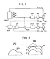
- reference character TR indicates a tracer head
- ST designates a stylus
- CTH identifies a cutter head
- C T denotes a cutter
- Ml represents a motor for feeding the tracer head TR in the Z-axis direction
- M2 shows a motor for feeding the cutter head CTH in the Z-axis direction
- P1 and P2 refer to position detectors for detecting the positions of the tracer head TR and the cutter head CTH in the Z-axis direction to yield position detection signals
- DV1 and DV2 indicate drive circuits for driving the motors Ml and M2, respectively
- ADD designates an adder
- TROP identifies a trace arithmetic unit
- SUP denotes a superimposing circuit
- OP represents an arithmetic circuit.
- a work table for mounting thereon a model and a workpiece two motors for feeding the work table in the X-axis and Y-axis directions and their drive circuits are not shown for the sake of brevity.
- the tracer head TR produces displacement signals Exr ⁇ y and ⁇ Z in the X-axis, Y-axis and Z-axis directions which correspond to displacement of the stylus ST moving in contact with a model (not shown), and the displacement signals are applied to the trace arithmetic unit TROP.
- the trace arithmetic unit TROP Based on the displacement signals ⁇ x , ⁇ y and ⁇ Z of the tracer head TR, the trace arithmetic unit TROP provides velocity signals V , V y and V Z indicating trace velocities in the X-axis, Y-axis and Z-axis directions.
- the velocity signals Vx and V y indicating the trace velocities in the X-axis and Y-axis directions are provided to drive circuits for operating motors (not shown) to feed the abovesaid work table (not shown) in the X-axis and Y-axis directions.
- the velocity signal V Z indicating the trace velocity in the Z-axis direction is applied to the drive circuit DV1 of the motor Ml for feeding the tracer to head TR in the Z-axis direction,and/the adder ADD. Accordingly, the tracer head TR is fed in the Z-axis direction at a velocity corresponding to the velocity signal V .
- the position of the tracer head TR thus fed in the Z-axis direction is always detected by the position detector Pl, from which the position detection signal indicating the detected position of the tracer head TR is provided to the superimposing circuit SUP.
- the superimposing circuit SUP is to superimpose the position detection signal from the position detector Pl and an infeed command signal for setting the infeed of the cutter CT, and the output signal of the superimposing circuit SUP is applied to one input terminal of the arithmetic circuit OP.
- the arithmetic circuit OP is to obtain the difference betweeen the output signal of the superimposing circuit SUP and the position detection signal from the position detector P2 which indicates the position of the cutter head CTH in the Z-axis direction.
- the output signal of the arithmetic circuit OP and the velocity V are added together by the adder ADD and the added output is provided to the drive circuit DV2 of the motor M2.
- the motor M2 feeds the cutter head CTH in the Z-axis direction at a velocity different from that of the tracer head TR in the Z-axis direction so that the position detection signal derived from the position detector P2 may become equal to the output signal from the superimposing circuit SUP.
- the position of the cutter head C T H in the Z-axis direction deviates from the position of the tracer head TR in the Z-axis direction by a distance corresponding to the infeed command signal.
- the output signal from the arithmetic circuit OP is reduced to zero, so that the cutter head CTH is fed in the Z-axis direction at the velocity corresponding to the velocity signal V , that is, at the same velocity as that of the tracer head TR fed in the Z-axis direction.
- the cutter CT can be moved along loci 1, 2 and 3 one after another by sequentially applying infeed command signals of predetermined distances, as depicted in Fig. 2(B), whereby it is possible to prevent breakage of the cutter CT or the like because of too large an infeed of the cutter.
- the/tracer which is in accordance with control system / the present invention is provided with a first drive system composed of the drive circuit DV1 and the motor Ml for feeding the tracer head in the Z-axis direction, a second drive system composed of the drive circuit DV2 and" the motor M2 for feeding the cutter head in the Z-axis direction, first and second position detectors for detecting the positions of the tracer head and the cutter head in the Z-axis direction, and a superimposing circuit for superimposing a position detection signal from the first position detector and an infeed_command signal on each other.
- the cutter head is fed by the second drive system in the Z-axis direction so that the difference between the output signal from the superimposing circuit and the position detection signal from the second position detector may be reduced to zero. Therefore, this has the advantage that the infeed of the cutter head in the Z-axis direction can freely be set without the necessity of newly providing a mechanical feed mechanism, means of by/applying an infeed signal to one of synchronously-controlled drive systems which are indispensable to the system configuration.
Landscapes
- Engineering & Computer Science (AREA)
- Automation & Control Theory (AREA)
- Mechanical Engineering (AREA)
- Machine Tool Copy Controls (AREA)
- Numerical Control (AREA)
Applications Claiming Priority (2)
| Application Number | Priority Date | Filing Date | Title |
|---|---|---|---|
| JP55118134A JPS6049542B2 (ja) | 1980-08-27 | 1980-08-27 | 倣い制御方式 |
| JP118134/80 | 1980-08-27 |
Publications (3)
| Publication Number | Publication Date |
|---|---|
| EP0046655A2 true EP0046655A2 (de) | 1982-03-03 |
| EP0046655A3 EP0046655A3 (en) | 1982-03-10 |
| EP0046655B1 EP0046655B1 (de) | 1985-03-20 |
Family
ID=14728883
Family Applications (1)
| Application Number | Title | Priority Date | Filing Date |
|---|---|---|---|
| EP81303769A Expired EP0046655B1 (de) | 1980-08-27 | 1981-08-19 | Kopiersteuergerät |
Country Status (5)
| Country | Link |
|---|---|
| US (1) | US4426180A (de) |
| EP (1) | EP0046655B1 (de) |
| JP (1) | JPS6049542B2 (de) |
| KR (1) | KR840002192B1 (de) |
| DE (1) | DE3169388D1 (de) |
Cited By (1)
| Publication number | Priority date | Publication date | Assignee | Title |
|---|---|---|---|---|
| EP0074462A3 (de) * | 1981-09-14 | 1983-08-17 | Mecof S.p.A. | Kopierfraesmaschine mit mindestens zwei beweglichen Staendern |
Families Citing this family (5)
| Publication number | Priority date | Publication date | Assignee | Title |
|---|---|---|---|---|
| JPS57168846A (en) * | 1981-04-10 | 1982-10-18 | Fanuc Ltd | Copying control method |
| JPS59152133A (ja) * | 1983-02-17 | 1984-08-30 | シ−ケ−デイ株式会社 | 包装箱の開蓋装置 |
| JPS60251019A (ja) * | 1984-05-17 | 1985-12-11 | ダイシン機工株式会社 | 空缶自動取出装置 |
| JPH01109057A (ja) * | 1987-10-23 | 1989-04-26 | Fanuc Ltd | デジタイジング方法 |
| US5283509A (en) * | 1989-04-12 | 1994-02-01 | Fanuc Ltd. | Tracing control system |
Family Cites Families (7)
| Publication number | Priority date | Publication date | Assignee | Title |
|---|---|---|---|---|
| US2307503A (en) | 1938-05-25 | 1943-01-05 | Westinghouse Electric & Mfg Co | Profiling control system |
| US2263765A (en) | 1938-08-06 | 1941-11-25 | Gridiron Steel Company | Ironing table |
| US3204533A (en) | 1963-04-11 | 1965-09-07 | Farrel Corp | Machine tool servo system |
| AT311151B (de) * | 1972-01-12 | 1973-11-12 | Siemens Ag | Einrichtung zum Nachstellen des Werkzeuges relativ zum Werkstück bei Kurvenfräsmaschinen oder Kurvenschleifmaschinen |
| US4044289A (en) | 1974-03-26 | 1977-08-23 | Textron Inc. | Cycling system for tracer-controlled machine tools |
| SU650784A1 (ru) | 1976-12-14 | 1979-03-05 | Особое Конструкторское Бюро Станкостроения | Копировально-фрезерный станок |
| FR2416767A1 (fr) * | 1978-02-08 | 1979-09-07 | Rondolotti Ets | Dispositif de copiage pour machine-outil |
-
1980
- 1980-08-27 JP JP55118134A patent/JPS6049542B2/ja not_active Expired
-
1981
- 1981-08-12 US US06/292,274 patent/US4426180A/en not_active Expired - Fee Related
- 1981-08-17 KR KR1019810002972A patent/KR840002192B1/ko not_active Expired
- 1981-08-19 EP EP81303769A patent/EP0046655B1/de not_active Expired
- 1981-08-19 DE DE8181303769T patent/DE3169388D1/de not_active Expired
Cited By (1)
| Publication number | Priority date | Publication date | Assignee | Title |
|---|---|---|---|---|
| EP0074462A3 (de) * | 1981-09-14 | 1983-08-17 | Mecof S.p.A. | Kopierfraesmaschine mit mindestens zwei beweglichen Staendern |
Also Published As
| Publication number | Publication date |
|---|---|
| JPS6049542B2 (ja) | 1985-11-02 |
| EP0046655B1 (de) | 1985-03-20 |
| US4426180A (en) | 1984-01-17 |
| EP0046655A3 (en) | 1982-03-10 |
| DE3169388D1 (en) | 1985-04-25 |
| KR830005970A (ko) | 1983-09-14 |
| KR840002192B1 (ko) | 1984-11-28 |
| JPS5748452A (en) | 1982-03-19 |
Similar Documents
| Publication | Publication Date | Title |
|---|---|---|
| EP0059759B1 (de) | Kopierkontrollsystem | |
| EP0303300A3 (de) | Werkzeugmaschinensteuerung | |
| EP0046655A2 (de) | Kopiersteuergerät | |
| EP0041382B1 (de) | Dreidimensionales Kopiersteuergerät | |
| EP0510208B1 (de) | Vorrichtung zur regelung von digitalisierungsvorgängen | |
| EP0209604A4 (de) | Schnittstellensystem für servoregelung. | |
| EP0029294B1 (de) | Kopiersteuerungsvorrichtung | |
| GB902421A (en) | Improvements in and relating to methods and apparatus for cutting shapes | |
| JPS6156059B2 (de) | ||
| EP0081589A1 (de) | Numerische steuereinheit | |
| EP0536413A1 (de) | Steuervorrichtung zum kopieren | |
| US2887639A (en) | Tracer synchronizing scheme for center drive lathes | |
| EP0386251A1 (de) | Profil-steuerungsverfahren | |
| GB1516983A (en) | Automatic tool and machining process | |
| EP0190357B1 (de) | Steuerungsvorrichtung der multidirektionellen profilierung | |
| EP0037720A2 (de) | Verfahren zur Maschinenbearbeitung mittels numerischer Daten | |
| US3611874A (en) | Combined numerical and tracer control system for machine tools | |
| US3515963A (en) | Outline following apparatus | |
| EP0420990B1 (de) | Kopiersteuergerät | |
| EP0065990A1 (de) | Steuersystem zum selbsttätigen kopieren | |
| JPH0732980B2 (ja) | 3次元形状の加工方法 | |
| US4325013A (en) | Electrical tracer control system utilizing sine wave resolution | |
| JPS614647A (ja) | Nc溶断用テ−プの作成方法及び装置 | |
| EP0146629B1 (de) | Vorrichtung zur steuerung der profilierung | |
| JPS60118452A (ja) | 数値制御装置における加工原点の形成方法 |
Legal Events
| Date | Code | Title | Description |
|---|---|---|---|
| PUAI | Public reference made under article 153(3) epc to a published international application that has entered the european phase |
Free format text: ORIGINAL CODE: 0009012 |
|
| PUAL | Search report despatched |
Free format text: ORIGINAL CODE: 0009013 |
|
| 17P | Request for examination filed |
Effective date: 19811023 |
|
| AK | Designated contracting states |
Designated state(s): DE FR GB |
|
| AK | Designated contracting states |
Designated state(s): DE FR GB |
|
| RBV | Designated contracting states (corrected) |
Designated state(s): CH DE FR GB IT LI LU NL SE |
|
| RBV | Designated contracting states (corrected) |
Designated state(s): DE FR GB |
|
| RAP1 | Party data changed (applicant data changed or rights of an application transferred) |
Owner name: FANUC LIMITED |
|
| GRAA | (expected) grant |
Free format text: ORIGINAL CODE: 0009210 |
|
| RAP1 | Party data changed (applicant data changed or rights of an application transferred) |
Owner name: FANUC LTD |
|
| AK | Designated contracting states |
Designated state(s): DE FR GB |
|
| REF | Corresponds to: |
Ref document number: 3169388 Country of ref document: DE Date of ref document: 19850425 |
|
| ET | Fr: translation filed | ||
| PLBE | No opposition filed within time limit |
Free format text: ORIGINAL CODE: 0009261 |
|
| STAA | Information on the status of an ep patent application or granted ep patent |
Free format text: STATUS: NO OPPOSITION FILED WITHIN TIME LIMIT |
|
| 26N | No opposition filed | ||
| PGFP | Annual fee paid to national office [announced via postgrant information from national office to epo] |
Ref country code: FR Payment date: 19890803 Year of fee payment: 9 |
|
| PGFP | Annual fee paid to national office [announced via postgrant information from national office to epo] |
Ref country code: DE Payment date: 19890814 Year of fee payment: 9 |
|
| PGFP | Annual fee paid to national office [announced via postgrant information from national office to epo] |
Ref country code: GB Payment date: 19890831 Year of fee payment: 9 |
|
| PG25 | Lapsed in a contracting state [announced via postgrant information from national office to epo] |
Ref country code: GB Effective date: 19900819 |
|
| GBPC | Gb: european patent ceased through non-payment of renewal fee | ||
| PG25 | Lapsed in a contracting state [announced via postgrant information from national office to epo] |
Ref country code: FR Effective date: 19910430 |
|
| PG25 | Lapsed in a contracting state [announced via postgrant information from national office to epo] |
Ref country code: DE Effective date: 19910501 |
|
| REG | Reference to a national code |
Ref country code: FR Ref legal event code: ST |