EP0048006B1 - Casier divisible pour bouteilles - Google Patents
Casier divisible pour bouteilles Download PDFInfo
- Publication number
- EP0048006B1 EP0048006B1 EP81107210A EP81107210A EP0048006B1 EP 0048006 B1 EP0048006 B1 EP 0048006B1 EP 81107210 A EP81107210 A EP 81107210A EP 81107210 A EP81107210 A EP 81107210A EP 0048006 B1 EP0048006 B1 EP 0048006B1
- Authority
- EP
- European Patent Office
- Prior art keywords
- crate
- locking
- brackets
- shaft
- slide
- Prior art date
- Legal status (The legal status is an assumption and is not a legal conclusion. Google has not performed a legal analysis and makes no representation as to the accuracy of the status listed.)
- Expired
Links
- 229920003023 plastic Polymers 0.000 claims description 2
- 239000004033 plastic Substances 0.000 claims description 2
- 239000000463 material Substances 0.000 claims 1
- 210000000078 claw Anatomy 0.000 description 2
- 230000007704 transition Effects 0.000 description 2
- 235000013405 beer Nutrition 0.000 description 1
- 238000010586 diagram Methods 0.000 description 1
- 239000000945 filler Substances 0.000 description 1
- 238000000034 method Methods 0.000 description 1
- 238000005192 partition Methods 0.000 description 1
- 230000000149 penetrating effect Effects 0.000 description 1
- 238000000926 separation method Methods 0.000 description 1
Images


Classifications
-
- B—PERFORMING OPERATIONS; TRANSPORTING
- B65—CONVEYING; PACKING; STORING; HANDLING THIN OR FILAMENTARY MATERIAL
- B65D—CONTAINERS FOR STORAGE OR TRANSPORT OF ARTICLES OR MATERIALS, e.g. BAGS, BARRELS, BOTTLES, BOXES, CANS, CARTONS, CRATES, DRUMS, JARS, TANKS, HOPPERS, FORWARDING CONTAINERS; ACCESSORIES, CLOSURES, OR FITTINGS THEREFOR; PACKAGING ELEMENTS; PACKAGES
- B65D21/00—Nestable, stackable or joinable containers; Containers of variable capacity
- B65D21/02—Containers specially shaped, or provided with fittings or attachments, to facilitate nesting, stacking, or joining together
- B65D21/0201—Containers specially shaped, or provided with fittings or attachments, to facilitate nesting, stacking, or joining together stackable or joined together side-by-side
- B65D21/0204—Containers specially shaped, or provided with fittings or attachments, to facilitate nesting, stacking, or joining together stackable or joined together side-by-side and joined together by interconnecting formations forming part of the container, e.g. dove-tail, snap connections, hook elements
-
- B—PERFORMING OPERATIONS; TRANSPORTING
- B65—CONVEYING; PACKING; STORING; HANDLING THIN OR FILAMENTARY MATERIAL
- B65D—CONTAINERS FOR STORAGE OR TRANSPORT OF ARTICLES OR MATERIALS, e.g. BAGS, BARRELS, BOTTLES, BOXES, CANS, CARTONS, CRATES, DRUMS, JARS, TANKS, HOPPERS, FORWARDING CONTAINERS; ACCESSORIES, CLOSURES, OR FITTINGS THEREFOR; PACKAGING ELEMENTS; PACKAGES
- B65D25/00—Details of other kinds or types of rigid or semi-rigid containers
- B65D25/28—Handles
- B65D25/32—Bail handles, i.e. pivoted rigid handles of generally semi-circular shape with pivot points on two opposed sides or wall parts of the conainter
Definitions
- the invention relates to a multi-part, in particular two-part plastic bottle crate with a partition running parallel to an outer wall, the part-bounding, adjoining auxiliary walls and interlocking interlocking elements in the form of a plurality of hooks projecting over the partial parts in the area of a vertical edge of each auxiliary wall in the area of the other vertical edge, which opens into a locking shaft and corresponds to the hook cross-section, wherein a locking slide is arranged in the shaft with the hooks projecting into the shaft of the corresponding part engaging behind the surface parts, and wherein each part is adjacent to its auxiliary wall Walls has an articulated support bracket which can be pivoted against the sections and which projects with the free ends of its legs over the articulations.
- the divisibility of commercially available bottle crates is desirable in order to facilitate handling, in particular removal from the point of sale, for the end user.
- the division should not affect the handling of such boxes by the filler, for example the brewery, and by the dealer.
- the invention has for its object to design such a bottle crate and in particular the locking of such a bottle crate so that the separation and Joining the box sections can be effected more easily.
- a divisible bottle crate of the type outlined at the outset which is characterized in that the bracket provided with an attachment at the free end of a leg has a recess in the wall of the corresponding locking shaft when the brackets are pivoted against the crate with this attachment engaging in a recess in the locking slide hold it in the locking position.
- the unlocking is effected by lifting the brackets assigned to each of the box sections, which are then also available for convenient transportation of the box sections. It is also easily possible to join two box sections to form a box when the brackets are raised, which are then locked together by folding the brackets.
- brackets fit into a recess of the box sections in the folded state.
- This configuration is connected with the fact that the box sections in the bottom area along the joint are provided with a continuous slot on the assembled box, which includes the locking shaft, ensuring the perfect stackability of such boxes.
- the slide is inserted into the overhead shaft from the open bottom side, a spring-loaded lock starting from the shaft behind the slide ensuring that the slide does not slip out of the shaft.
- the slide is profiled and has longitudinal grooves in which guide strips engage, starting from the correspondingly designed shaft.
- the shaft receiving the slide projects to a limited extent over the auxiliary wall and the area equipped with the locking hooks is set back accordingly in order not to reduce the usable space of the box section too much in the shaft area. This is helped if the profiled slide and thus also the shaft receiving the slide receives an approximately trapezoidal cross-section, the short leg of the trapezoid corresponding approximately to the thickness of the box wall to which it adjoins.
- the bracket is preferably provided with studs molded onto it, which can be blasted into elongated holes provided in the corresponding wall parts of the box section.
- a limitation of the swivel bracket area by a stop on the box section can be provided.
- the bracket in the locking position i.e. in the pivoted state against the box section
- the box consists of the sections 11 and 11 'with the outer walls 111, 112, 113 and 111', 112 ', 113', the bottom 114 and 114 'and the auxiliary walls 116 and 116', respectively, which are joined together to form the box Box sections 11, 11 'rest against each other ( Figure 1).
- the wall and, if appropriate, also the floor elements 111, 111 'to 116, 116' are provided with recesses or openings in a manner known per se.
- the box sections 11, 11 ' are divided in a manner known per se into a plurality of compartments each receiving a bottle or the like.
- Each box section 11, 11 ' is provided at the transition of the auxiliary walls 116 and 116' into an outer wall 113 and 113 'with an above-closed (1171) shaft 117 and 117' which extends over the height of the box and at the transition of the auxiliary walls 116, 116 'd in the otherêtwa "111 or 111' with a plurality of spaced apart on the auxiliary walls 116, 116 'projecting hooks with downward claw 1181, of which in the drawing (figures 2 to 4) the hooks 118 'extending from the box section 113' can be seen.
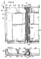
- the locking mechanism is further explained on the basis of the locking mechanism V1 shown in detail in FIGS. 2 to 4.
- the lock V2 on the opposite side is designed accordingly.
- recesses 1172 are provided in the wall of the shaft 117 forming a component of the corresponding box section 11, which, in the case of assembled box sections 11 and 11 ', start from those emanating from the box section 11' Hook 118 'can be reached.
- a slide 119 which can be displaced in the shaft 117 in the direction of the double arrow A in FIG. 2, has recesses 1191 (in particular FIG. 4) at corresponding intervals, into which the hooks 118 'penetrating the shaft wall when the box sections 11, 11' are joined together.
- the recesses 1191 in the slide 119 merge into a sack-like recess 1192 (in particular FIG. 4) into which the claw 1181 of the hook 118 ′ is inserted when the slide is raised (FIG. 2), as a result of which the box sections 11, 11 ′ are locked together becomes.
- the slider 119 is lifted and held in the locking position (FIG. 2) by the bracket 121 assigned to the section 11.
- the bracket 121 pivoted on the box section 11 at 1111 and 1131 in the sense of the double arrow B in FIG the articulation 1131 of the projecting leg 1211 has a recess 1173 (in particular FIG. 4) in the wall of the shaft 117 facing it, engages under a recess 1193 (in particular FIG. 4) in the slide 119 and transfers the slide 119 into the locking position when pivoting against the box section 11 ( Figure 2) in which he then holds it.
- bracket 121 For unlocking, the bracket 121 is raised (FIG. 4) and the slide 119 which runs smoothly in the shaft 117 slides down, thereby releasing the hooks 118 'forming part of the other box section 11', so that the box sections 11 and 11 'can be separated.
- the bracket 121 forming part of the box section 11 is then also available for transporting the box section 11, as is the component of the box section 11 'forming bracket 121' which unlocks the locking V2.
- the slide 119 which has an essentially pentagonal cross section, is provided with two longitudinal grooves 1194, 1194 ', into which guide strips 1174, 1174' projecting into the shaft 117 engage (FIG. 3).
- a lock 1176, 1196 prevents the slide 119 inserted into the shaft 117 from the bottom from slipping out of the shaft 117 (in particular FIG. 2).
- brackets 121, 121 'pivoted against the box sections 11, 11' fit flush in the corresponding recesses on the circumference of the box sections 11, 11 ', for example 122.
- Recesses 123, 123' on the bottom 114, 114 'of the box sections 11, 11' in conjunction with recesses 124, known per se, on the circumference of the box ensure the stable stackability of the box.
- the brackets 121, 121 ' with stud bolts molded onto them, for example 1212 in FIGS. 2 and 3, are pushed into elongated holes provided for this purpose, for example 1131 in FIG. 2. Stops, for example 1132 in FIG. 4, on the box sections 11, 11 'limit the pivoting range of the brackets 121, 121' in such a way that they can be pivoted at most into the vertical position shown in FIG. 4.
- brackets 121, 121' are fixed by cams 1213 which snap into corresponding recesses 1121 in the box wall 112 and are molded onto the brackets 121, 121 '.
Landscapes
- Engineering & Computer Science (AREA)
- Mechanical Engineering (AREA)
- Rigid Containers With Two Or More Constituent Elements (AREA)
- Stackable Containers (AREA)
- Details Of Rigid Or Semi-Rigid Containers (AREA)
Claims (8)
Priority Applications (1)
| Application Number | Priority Date | Filing Date | Title |
|---|---|---|---|
| AT81107210T ATE8233T1 (de) | 1980-09-13 | 1981-09-12 | Teilbarer flaschenkasten. |
Applications Claiming Priority (2)
| Application Number | Priority Date | Filing Date | Title |
|---|---|---|---|
| DE3034650 | 1980-09-13 | ||
| DE3034650A DE3034650C2 (de) | 1980-09-13 | 1980-09-13 | Teilbarer Flaschenkasten |
Publications (2)
| Publication Number | Publication Date |
|---|---|
| EP0048006A1 EP0048006A1 (fr) | 1982-03-24 |
| EP0048006B1 true EP0048006B1 (fr) | 1984-07-04 |
Family
ID=6111905
Family Applications (1)
| Application Number | Title | Priority Date | Filing Date |
|---|---|---|---|
| EP81107210A Expired EP0048006B1 (fr) | 1980-09-13 | 1981-09-12 | Casier divisible pour bouteilles |
Country Status (4)
| Country | Link |
|---|---|
| US (1) | US4387824A (fr) |
| EP (1) | EP0048006B1 (fr) |
| AT (1) | ATE8233T1 (fr) |
| DE (1) | DE3034650C2 (fr) |
Families Citing this family (34)
| Publication number | Priority date | Publication date | Assignee | Title |
|---|---|---|---|---|
| JPS60184816U (ja) * | 1984-05-17 | 1985-12-07 | 麒麟麦酒株式会社 | 連結可能な合成樹脂製壜箱 |
| JPS6114621U (ja) * | 1984-06-28 | 1986-01-28 | 麒麟麦酒株式会社 | 連結可能な合成樹脂製壜箱 |
| JPS6114620U (ja) * | 1984-06-28 | 1986-01-28 | 麒麟麦酒株式会社 | 連結可能な合成樹脂製壜箱 |
| JPS6114616U (ja) * | 1984-06-28 | 1986-01-28 | 麒麟麦酒株式会社 | 連結可能な合成樹脂製壜箱 |
| JPS6114645U (ja) * | 1984-06-28 | 1986-01-28 | 麒麟麦酒株式会社 | 連結可能な合成樹脂製壜箱 |
| JPS6114619U (ja) * | 1984-06-28 | 1986-01-28 | 麒麟麦酒株式会社 | 連結可能な合成樹脂製壜箱 |
| JPS6114623U (ja) * | 1984-06-28 | 1986-01-28 | 麒麟麦酒株式会社 | 連結可能な合成樹脂製壜箱 |
| JPS6114622U (ja) * | 1984-06-28 | 1986-01-28 | 麒麟麦酒株式会社 | 連結可能な合成樹脂製壜箱 |
| JPS6111350A (ja) * | 1984-06-28 | 1986-01-18 | 麒麟麦酒株式会社 | 連結可能な合成樹脂製壜箱 |
| JPH0228180Y2 (fr) * | 1985-02-19 | 1990-07-30 | ||
| JPH0228179Y2 (fr) * | 1985-02-19 | 1990-07-30 | ||
| JPH0231381Y2 (fr) * | 1985-04-05 | 1990-08-24 | ||
| DE3533114A1 (de) * | 1985-09-17 | 1987-03-26 | Berolina Kunststoff | Teilbarer flaschenkasten |
| US4793492A (en) * | 1986-11-14 | 1988-12-27 | Frank Halbich | Homecare pillbox |
| US4785604A (en) * | 1987-03-17 | 1988-11-22 | Johnson Jr Robert H | Collapsible gridworks for forming structures by confining fluent materials |
| US4945689A (en) * | 1987-03-17 | 1990-08-07 | Johnson Jr Robert H | Collapsible gridwork for forming structures by confining fluent materials |
| DE3912321A1 (de) * | 1989-04-14 | 1990-10-25 | Split Box Patentverwertung | Teilbarer kunststoff-flaschenkasten |
| DE3909352A1 (de) * | 1989-03-22 | 1990-09-27 | Wilhelm Goetz | Zweiteiliger kasten aus kunststoff od. dgl. |
| DE59002245D1 (de) * | 1989-03-30 | 1993-09-16 | Schoeller Plast Ag | Teilbarer behaelter, insbesondere flaschenkasten. |
| DE3910735A1 (de) * | 1989-04-03 | 1990-10-04 | Berolina Kunststoff | Teilbarer flaschenkasten |
| FR2674505A1 (fr) * | 1991-03-29 | 1992-10-02 | Allibert Sa | Casier en matiere plastique moulee a anses repliables. |
| US5267873A (en) * | 1991-11-12 | 1993-12-07 | Unisys Corporation | Inter-box coupling |
| US5273175A (en) * | 1993-01-28 | 1993-12-28 | Rehrig Pacific Company, Inc. | Split box case construction |
| US5344021A (en) * | 1993-09-21 | 1994-09-06 | Formall, Inc. | Molded crate with interlocking rim appliances |
| USD384230S (en) * | 1996-03-18 | 1997-09-30 | Hollanding Inc. | Top for a mobile storage unit |
| AU2002240570B2 (en) | 2001-02-28 | 2008-07-31 | Al M. Arellanes | Fluent material confinement system |
| US7591611B2 (en) | 2001-02-28 | 2009-09-22 | Geocell Systems, Inc. | Fluent material confinement system |
| ITMI20030163U1 (it) * | 2003-04-07 | 2004-10-08 | Whirlpool Co | Cassetto mobile ed asportabile per frigorifero con maniglia di presa |
| US9475602B2 (en) * | 2008-10-06 | 2016-10-25 | Rehrig Pacific Company | Stackable low depth tray |
| HUE032226T2 (en) | 2013-04-18 | 2017-09-28 | Ds Smith Plastics Karlovac D O O | Can be divided into a bottle holder |
| MX2015016756A (es) | 2014-12-04 | 2016-06-03 | Rehrig Pacific Co | Caja para bebidas. |
| CA2917506A1 (fr) | 2015-01-14 | 2016-07-14 | Rehrig Pacific Company | Caisse a claire-voie pour boissons dotee de poignees |
| CN107380732B (zh) * | 2017-08-28 | 2018-12-11 | 重庆洁邦电器有限公司 | 便于多种类储存的真空储粮装置 |
| USD831962S1 (en) | 2017-12-22 | 2018-10-30 | Rehrig Pacific Company | Beverage crate |
Family Cites Families (10)
| Publication number | Priority date | Publication date | Assignee | Title |
|---|---|---|---|---|
| US2732969A (en) * | 1956-01-31 | browne | ||
| US2311723A (en) * | 1941-08-23 | 1943-02-23 | Tillman R Anderson | Sectional case |
| US2610760A (en) * | 1948-08-30 | 1952-09-16 | Dexter D Ball | Sectional container |
| DE1171328B (de) * | 1962-01-10 | 1964-05-27 | Gunnar Lundstedt | Kiste |
| US3297196A (en) * | 1965-05-06 | 1967-01-10 | Cornelius Co | Bottle carrier |
| US3317081A (en) * | 1965-06-14 | 1967-05-02 | Cornelius Co | Bottle carrier |
| US3603475A (en) * | 1969-06-16 | 1971-09-07 | Gerald Erickson | Interlocking means for divisible container carrier |
| DE7518030U1 (de) * | 1975-06-06 | 1976-03-18 | Schoeller & Co Kg | Kunststoff-Flaschenkasten mit Verriegelungsvorrichtung |
| DE2525169C3 (de) * | 1975-06-06 | 1978-09-07 | Schoeller Gmbh & Co Kg, 3400 Goettingen | Kunststoff-Flaschenkasten mit Verriegelungsvorrichtung |
| DE7923328U1 (de) * | 1979-08-16 | 1979-11-29 | Wefers Werner | Flaschenkasten |
-
1980
- 1980-09-13 DE DE3034650A patent/DE3034650C2/de not_active Expired
-
1981
- 1981-09-12 EP EP81107210A patent/EP0048006B1/fr not_active Expired
- 1981-09-12 AT AT81107210T patent/ATE8233T1/de not_active IP Right Cessation
- 1981-10-07 US US06/309,176 patent/US4387824A/en not_active Expired - Lifetime
Also Published As
| Publication number | Publication date |
|---|---|
| ATE8233T1 (de) | 1984-07-15 |
| DE3034650A1 (de) | 1982-04-22 |
| DE3034650C2 (de) | 1983-04-07 |
| US4387824A (en) | 1983-06-14 |
| EP0048006A1 (fr) | 1982-03-24 |
Similar Documents
| Publication | Publication Date | Title |
|---|---|---|
| EP0048006B1 (fr) | Casier divisible pour bouteilles | |
| DE69321973T2 (de) | Transportbehälter mit selbstschliessendem oberrand | |
| DE60014368T2 (de) | Stapelbares Behältersystem | |
| DE9218977U9 (de) | Behälter aus Kunststoff, insbesondere Gemüsebehälter, mit klappbaren Seitenwänden | |
| DE9321234U1 (de) | Behälter aus Kunststoff, insbesondere Gemüsebehälter mit klappbaren Seitenwänden | |
| EP0253363B1 (fr) | Casiers à bouteilles empilables | |
| CH422633A (de) | Satz von Lager- und Transportbehältern | |
| DE102010037517B3 (de) | Lager- und Transportbehälter | |
| WO1998034838A2 (fr) | Recipient, notamment pour le transport de fruits et de legumes | |
| DE3044471A1 (de) | Bauteile aus kunststoff zur herstellung einer schublade | |
| EP0429015B1 (fr) | Récipient de stockage subdivisible pour petits objets ou similaires | |
| DE2729737A1 (de) | Dicht verschliessbarer, unterteilbarer behaelter | |
| EP0860366A1 (fr) | Conteneur pliable | |
| DE19948124B4 (de) | Zerlegbare Stapelkiste | |
| EP0091718B1 (fr) | Caisse de transport pliante | |
| DE102004006416A1 (de) | Mehrwegbehälter zum Transportieren von Stückgut | |
| DE3633348A1 (de) | Zusammenlegbarer transportbehaelter fuer stueckgueter | |
| DE102004006415B4 (de) | Behälter | |
| DE9415663U1 (de) | Sockel für Warenträger | |
| DE2902689C2 (de) | Behälter für den Transport gefährlicher Flüssigkeiten | |
| DE2200945A1 (de) | Stapel- und verschachtelbarer Behaelter | |
| DE4126749A1 (de) | Behaelter aus kunststoff zur aufnahme von gegenstaenden | |
| DE4333626C2 (de) | Transportkasten aus Kunststoff | |
| DE1536038C (de) | Stapelbare Gemusesteige aus Kunst stoff | |
| DE2954497C2 (de) | Stapelbarer Transport- und Lagersichtkasten aus Kunststoff |
Legal Events
| Date | Code | Title | Description |
|---|---|---|---|
| PUAI | Public reference made under article 153(3) epc to a published international application that has entered the european phase |
Free format text: ORIGINAL CODE: 0009012 |
|
| AK | Designated contracting states |
Designated state(s): AT BE CH FR GB IT LU NL SE |
|
| 17P | Request for examination filed |
Effective date: 19820212 |
|
| ITF | It: translation for a ep patent filed | ||
| GRAA | (expected) grant |
Free format text: ORIGINAL CODE: 0009210 |
|
| AK | Designated contracting states |
Designated state(s): AT BE CH FR GB IT LI LU NL SE |
|
| REF | Corresponds to: |
Ref document number: 8233 Country of ref document: AT Date of ref document: 19840715 Kind code of ref document: T |
|
| ET | Fr: translation filed | ||
| BECH | Be: change of holder |
Free format text: 840704 *SPLIT-BOX PATENTVERWERTUNG K.G. |
|
| PLBE | No opposition filed within time limit |
Free format text: ORIGINAL CODE: 0009261 |
|
| STAA | Information on the status of an ep patent application or granted ep patent |
Free format text: STATUS: NO OPPOSITION FILED WITHIN TIME LIMIT |
|
| 26N | No opposition filed | ||
| ITPR | It: changes in ownership of a european patent |
Owner name: CESSIONE;SPLIT - BOX PATENTVERWERTUNG KG |
|
| REG | Reference to a national code |
Ref country code: CH Ref legal event code: PUE Owner name: SPLIT-BOX PATENTVERWERTUNG KG |
|
| REG | Reference to a national code |
Ref country code: FR Ref legal event code: TP |
|
| NLS | Nl: assignments of ep-patents |
Owner name: SPLIT-BOX PATENTVERWERTUNG KG TE DORTMUND, BONDSRE |
|
| REG | Reference to a national code |
Ref country code: GB Ref legal event code: 732 |
|
| ITTA | It: last paid annual fee | ||
| EPTA | Lu: last paid annual fee | ||
| EAL | Se: european patent in force in sweden |
Ref document number: 81107210.7 |
|
| PGFP | Annual fee paid to national office [announced via postgrant information from national office to epo] |
Ref country code: SE Payment date: 19990914 Year of fee payment: 19 |
|
| PGFP | Annual fee paid to national office [announced via postgrant information from national office to epo] |
Ref country code: AT Payment date: 19990928 Year of fee payment: 19 |
|
| PGFP | Annual fee paid to national office [announced via postgrant information from national office to epo] |
Ref country code: NL Payment date: 19990930 Year of fee payment: 19 Ref country code: FR Payment date: 19990930 Year of fee payment: 19 |
|
| PGFP | Annual fee paid to national office [announced via postgrant information from national office to epo] |
Ref country code: GB Payment date: 19991007 Year of fee payment: 19 |
|
| PGFP | Annual fee paid to national office [announced via postgrant information from national office to epo] |
Ref country code: BE Payment date: 19991119 Year of fee payment: 19 |
|
| PGFP | Annual fee paid to national office [announced via postgrant information from national office to epo] |
Ref country code: CH Payment date: 19991129 Year of fee payment: 19 |
|
| PGFP | Annual fee paid to national office [announced via postgrant information from national office to epo] |
Ref country code: LU Payment date: 19991208 Year of fee payment: 19 |
|
| PG25 | Lapsed in a contracting state [announced via postgrant information from national office to epo] |
Ref country code: LU Free format text: LAPSE BECAUSE OF EXPIRATION OF PROTECTION Effective date: 20000912 Ref country code: GB Free format text: LAPSE BECAUSE OF NON-PAYMENT OF DUE FEES Effective date: 20000912 Ref country code: AT Free format text: LAPSE BECAUSE OF NON-PAYMENT OF DUE FEES Effective date: 20000912 |
|
| PG25 | Lapsed in a contracting state [announced via postgrant information from national office to epo] |
Ref country code: SE Free format text: THE PATENT HAS BEEN ANNULLED BY A DECISION OF A NATIONAL AUTHORITY Effective date: 20000929 |
|
| PG25 | Lapsed in a contracting state [announced via postgrant information from national office to epo] |
Ref country code: LI Free format text: LAPSE BECAUSE OF NON-PAYMENT OF DUE FEES Effective date: 20000930 Ref country code: CH Free format text: LAPSE BECAUSE OF NON-PAYMENT OF DUE FEES Effective date: 20000930 Ref country code: BE Free format text: LAPSE BECAUSE OF NON-PAYMENT OF DUE FEES Effective date: 20000930 |
|
| BERE | Be: lapsed |
Owner name: SPLIT-BOX PATENTVERWERTUNG K.G. Effective date: 20000930 |
|
| PG25 | Lapsed in a contracting state [announced via postgrant information from national office to epo] |
Ref country code: NL Free format text: LAPSE BECAUSE OF NON-PAYMENT OF DUE FEES Effective date: 20010401 |
|
| GBPC | Gb: european patent ceased through non-payment of renewal fee |
Effective date: 20000912 |
|
| REG | Reference to a national code |
Ref country code: CH Ref legal event code: PL |
|
| EUG | Se: european patent has lapsed |
Ref document number: 81107210.7 |
|
| PG25 | Lapsed in a contracting state [announced via postgrant information from national office to epo] |
Ref country code: FR Free format text: LAPSE BECAUSE OF NON-PAYMENT OF DUE FEES Effective date: 20010531 |
|
| NLV4 | Nl: lapsed or anulled due to non-payment of the annual fee |
Effective date: 20010401 |
|
| REG | Reference to a national code |
Ref country code: FR Ref legal event code: ST |