EP0049943B1 - Bewegliche Magnetkopfanordnung für einen flexiblen doppelseitigen Plattenspeicher - Google Patents
Bewegliche Magnetkopfanordnung für einen flexiblen doppelseitigen Plattenspeicher Download PDFInfo
- Publication number
- EP0049943B1 EP0049943B1 EP81303740A EP81303740A EP0049943B1 EP 0049943 B1 EP0049943 B1 EP 0049943B1 EP 81303740 A EP81303740 A EP 81303740A EP 81303740 A EP81303740 A EP 81303740A EP 0049943 B1 EP0049943 B1 EP 0049943B1
- Authority
- EP
- European Patent Office
- Prior art keywords
- support arm
- carriage
- disk
- assembly
- head
- Prior art date
- Legal status (The legal status is an assumption and is not a legal conclusion. Google has not performed a legal analysis and makes no representation as to the accuracy of the status listed.)
- Expired
Links
Images

Classifications
-
- G—PHYSICS
- G11—INFORMATION STORAGE
- G11B—INFORMATION STORAGE BASED ON RELATIVE MOVEMENT BETWEEN RECORD CARRIER AND TRANSDUCER
- G11B5/00—Recording by magnetisation or demagnetisation of a record carrier; Reproducing by magnetic means; Record carriers therefor
- G11B5/48—Disposition or mounting of heads or head supports relative to record carriers ; arrangements of heads, e.g. for scanning the record carrier to increase the relative speed
- G11B5/54—Disposition or mounting of heads or head supports relative to record carriers ; arrangements of heads, e.g. for scanning the record carrier to increase the relative speed with provision for moving the head into or out of its operative position or across tracks
- G11B5/55—Track change, selection or acquisition by displacement of the head
- G11B5/5521—Track change, selection or acquisition by displacement of the head across disk tracks
-
- G—PHYSICS
- G11—INFORMATION STORAGE
- G11B—INFORMATION STORAGE BASED ON RELATIVE MOVEMENT BETWEEN RECORD CARRIER AND TRANSDUCER
- G11B5/00—Recording by magnetisation or demagnetisation of a record carrier; Reproducing by magnetic means; Record carriers therefor
- G11B5/48—Disposition or mounting of heads or head supports relative to record carriers ; arrangements of heads, e.g. for scanning the record carrier to increase the relative speed
- G11B5/54—Disposition or mounting of heads or head supports relative to record carriers ; arrangements of heads, e.g. for scanning the record carrier to increase the relative speed with provision for moving the head into or out of its operative position or across tracks
-
- G—PHYSICS
- G11—INFORMATION STORAGE
- G11B—INFORMATION STORAGE BASED ON RELATIVE MOVEMENT BETWEEN RECORD CARRIER AND TRANSDUCER
- G11B5/00—Recording by magnetisation or demagnetisation of a record carrier; Reproducing by magnetic means; Record carriers therefor
- G11B5/48—Disposition or mounting of heads or head supports relative to record carriers ; arrangements of heads, e.g. for scanning the record carrier to increase the relative speed
- G11B5/56—Disposition or mounting of heads or head supports relative to record carriers ; arrangements of heads, e.g. for scanning the record carrier to increase the relative speed with provision for moving the head support for the purpose of adjusting the position of the head relative to the record carrier, e.g. manual adjustment for azimuth correction or track centering
-
- G—PHYSICS
- G11—INFORMATION STORAGE
- G11B—INFORMATION STORAGE BASED ON RELATIVE MOVEMENT BETWEEN RECORD CARRIER AND TRANSDUCER
- G11B5/00—Recording by magnetisation or demagnetisation of a record carrier; Reproducing by magnetic means; Record carriers therefor
- G11B5/48—Disposition or mounting of heads or head supports relative to record carriers ; arrangements of heads, e.g. for scanning the record carrier to increase the relative speed
- G11B5/58—Disposition or mounting of heads or head supports relative to record carriers ; arrangements of heads, e.g. for scanning the record carrier to increase the relative speed with provision for moving the head for the purpose of maintaining alignment of the head relative to the record carrier during transducing operation, e.g. to compensate for surface irregularities of the latter or for track following
Definitions
- This invention relates to the movable magnetic head block assemblies employed in double sided flexible magnetic disk storage devices.
- double sided flexible magnetic disk storage devices are widely used as the auxiliary or secondary storage equipment associated mainly with small scale computers.
- the storage medium, the double sided flexible magnetic disk can be removed and replaced, and accordingly to ensure uniformity and compatibility between magnetic disks recorded on the same or other machines, the positioning of the electromagnetic transducers-the heads-in relation to the rotation centre of the magnetic disk, along three axes, i.e. the radial direction of the disk, the direction tangential to the tracking circumference, and the azimuth, i.e. the angle of the head gap with relation to the recording track direction, must be executed with high accuracy, consistency, and reliability.
- Either or both these contacting surfaces may comprise a magnetic head, whereby either or both sides of the magnetic disk may be recorded on or read from, the arrangement with heads on both sides of the disk being particularly useful in that it allows both sides of the disk to be employed alternately or continuously without having to turn the disk over. Constructions employing heads on both sides of the disk are described in United States Patent No. 4,089,029 and 3,946,439, issued to Castrodale et al.
- the means for allowing the contacting surfaces to be retracted from the surface of the magnetic disk comprised mounting the contacting surfaces on support arms which were flexibly joined via thin cantilever springs to a carriage, such that the arms could be raised at one end, the contacting surface supporting end, either independently or, with two arms, cooperatively together, via a suitable means of mechanical interconnection, through an arc about a point of flexure in the cantilever springs and against the pressure of those cantilever springs and any auxiliary pressure spring.
- the thin leaf springs were secured to the carriage by means of screws which directly clamp down the thin springs against the carriage.
- the aforementioned position setting of the magnetic heads in this arrangement was carried out essentially in two stages, comprising a first stage, an approximate positioning stage, including the mounting of the magnetic heads to their respective arms, and a second stage of accurately positioning the magnetic heads in relation to the rotational center of the disk, comprising adjusting the position of the arms by loosening the screws fastening the carriage end of the cantilever springs to the support frame, adjusting the position of the arms, and hence the magnetic heads, in accordance with a test signal recorded on a setting-up magnetic disk, and then retightening the screws to secure the arms in the correct positions.
- the present invention seeks to mitigate at least some of the aforementioned drawbacks and in particular to provide a construction which allows easy, accurate and reliable position setting of the magnetic heads in relation to the rotational centre of the magnetic disk.
- a movable magnetic head block assembly for a double sided flexible magnetic disk storage device comprising:
- a floppy disk 1 comprising a jacket 3 housing a disk 2 coated on both sides with a magnetic material is inserted into a movable magnetic head block assembly 6 with slots 4 provided on each side of the jacket 3 to allow the magnetic heads 40 and 70 within the head assembly 6 to pass through to make intimate contact with the surfaces of the disk 2 to allow information to be recorded on or retrieved from either side of the disk 2 while it is rotated by any suitable known drive means, about its rotational centre 5.
- the movable magnetic head block assembly 6 includes a carriage 8 mounted in sliding relationship on a pair of parallel rails or rods 12, parallel to a radius of the floppy disk, the rods 12 passing through through-holes 10 provided in the lower portion of the carriage 8.
- the carriage 8 is arranged to be suitably driven by a suitable well-known drive means (not shown) in coordination with the rotation of the magnetic disk 2 to enable the whole of the usable surface of the disk 2 to be recorded on or read from.
- a support spar 13 Extending vertically and then horizontally towards the rotational centre 5 of the disk 2, from the end of the carriage 8 away from the rotational centre 5 of the disk 2 substantially in parallel to the lower portion of the carriage 8, is a support spar 13, to the upper and lower sides 14 and 15 of which are respectively mechanically rigidly fixed by mechanical fixing means such as screws 16, an upper support arm assembly 20 and a lower support arm assembly 50.
- the screws 16 in the illustrated embodiment pass through holes (not shown) provided in the anchor member portions 28 and 58 of arm assemblies 20 and 50 to engage with suitably threaded holes (not shown) provided in the support spar 13, and are arranged so that they may be slackened and then retightened to allow fine adjustment of the positions of the arm assemblies 20 and 50 with respect to the spar 13.
- Each support arm assembly 20 and 50 respectively comprises an anchor member 28 and 58, and a support arm,22 and 52 flexibly joined via cantilever type leaf springs 24 and 54, typically formed of stainless steel and about 0.1 mm thick by 20 mm wide, to opposite ends of which the support arm 22 or 52 and the anchor member 28 or 58 are respectively mechanically rigidly fixed, by means such as a firm press fit and screws 18 respectively.
- the anchor members 28 and 58 may optionally, as illustrated, be provided with raised rigid plinths 30 and 60 to which the cantilever springs 24 and 54 are respectively mechanically rigidly secured by screws 18 which pass through holes (not shown) in the cantilever springs 24 and 54 to engage with suitably threaded holes (not shown) provided in the plinth portions 30 and 60 of the anchor members 28 and 58.
- the flexible means employed, in this embodiment cantilever leaf springs 12 and 32, should be fundamentally of a nature that allows movement in one direction only, i.e. the direction of or against the arrows A and B in Figure 2, while providing resistance to lateral and longitudinal movement, to ensure accurate positioning of the heads in normal operation.
- a leaf spring is ideal as it allows flexing, or movement, only in the direction perpendicular to its surface of maximum area.
- a leaf spring as opposed to other suitable flexible means, such as hinges, allows the flexing means to supply at least a portion of the force required to urge the support arms 22 and 52 in the directions shown by the arrows A and B respectively, with sufficient force to prevent the support arms 22 and 52 from being disturbed by undulations or surface irregularities in the disk 2.
- auxiliary pressure leaf springs 38 and 68 which are positioned with their one ends placed on top of the fixed ends of the cantilever springs 24 and 54 respectively and secured by the screws, the aforementioned screws 18, that secure the cantilever springs 24 and 54, and with their other ends free, but arranged so as to physically contact the surfaces of the support arms 22 and 52 away from the disk 2 to apply additional pressure to the support arms 22 and 52 to urge them in the directions shown by the arrows A and B respectively, in cooperation with the cantilever springs 24 and 54.
- these stops 36 and 66 are provided by extending rigid longitudinal members 32 and 62 from the sides of the respective anchor members 28 and 58, to which they are mechanically rigidly joined, or with with they are rigidly integrally formed, and spanning cross members 34 and 64 between the longitudinal members 32, or 62, said cross members 34 and 64 being mechanically rigidly joined to or rigidly integrally formed with the longitudinal members 32 or 62, and having the stops 36 and 66 extending inwardly of the frames 26 and 56 respectively formed by the anchor members 28 and 58, the longitudinal members 32 and 62 and the cross members 34 and 64, to engage on the upper surface thereof with the disk side surfaces of the leading edges 23 and 53 of the support arms 22 and 52.
- an electromagnetic transducer head assembly comprising a mutually opposing pair of disk contacting surfaces, 39 and 59 which, in the present embodiment, respectively include an upper and a lower electromagnetic transducers, magnetic head groups 40 and 70, of any known suitable construction each including the necessary elements to perform the desired functions of erasure, recording and retrieval of information on the respective sides of the disk 2, each head group 40 and 70 being mounted respectively to the support arms 22 and 52 at positions on the mutually opposing surfaces thereof which are also substantially mutually opposed, at a point near to the ends of the arms 22 and 52 away from the ends to which the cantilever springs 24 and 54 are fixed.
- the magnetic head groups 40 and 70 are respectively resiliently mounted to the support arms 22 and 52 via flexible means such as leaf springs 42 and 72 by means of a pressure fit or adhesive bonding, and the springs 42 and 72 in this embodiment are pressure fit or adhesive bonded to projecting ridge-like portions 44 and 74 surrounding depressions 46 and 76, over which the magnetic heads 40 and 70 are mounted.
- the leaf springs 42 and 72 serve to press the magnetic head groups 40 and 70 against the surfaces of the disk 2 with a required force, while allowing a certain resilience to accommodate movement induced by undulations and surface irregularities in the surface of the disk 2 in use.
- these means comprise means for swinging each of the support arms 22 and 52 about a point of flexure in the cantilever springs 24 and 54, against the pressure of the cantilever springs 24 and 54 and the auxiliary springs 38 and 68, so that the magnetic head groups 40 and 70 carried thereon are separated by a distance at least greater than h, the thickness of the floppy disk 1.
- the mechanism by which the support arms 22 and 52 are retracted comprises a cross- piece 80 mechanically rigidly fixed to or formed integrally with the upper support arm 22, arranged to be physically engaged by hand or by any suitable mechanical or electromechanical arrangement capable of withdrawing the support arm 22 against the pressure of the leaf springs 24 and 38, in the direction opposite to the direction of arrow A.
- This arrangement may be duplicated for the lower support arm 52, or, for simplicity, the upper and lower support arms 22 and 52 may be mechanically interlinked so that a withdrawal of the upper support arm 22 creates a corresponding movement in the lower support arm 52.
- the portion of either of the contacting pegs 48 and 78 which is in contact with the surface of the other peg may be given a smooth rounded portion to provide a smoother "cam" interaction of the pegs.
- the floppy disk 1 To record or retrieve information in a floppy disk 1, firstly the floppy disk 1 must be inserted into the magnetic head block assembly, 6, which magnetic head block assembly 6 will then be suitably driven along the rails 12 in the radial direction of the disk 2 of the floppy disk 1 while the disk 2 is rotated about its central axis or rotational centre 5, by a suitable well known drive mechanism (not shown).
- This arrangement with magnetic head groups 40 and 70 positioned so that one magnetic head group faces each of the two faces of the disk 2, enables the entire useful surface of the disk 2 to be scanned for recording or retrieval, without having to remove or turn over the floppy disk 1.
- the magnetic head groups 40 and 70 must be in resilient intimate contact with the surfaces of the disk 2, for which purpose they are mounted on pressure springs 42 and 72 respectively, which urge them against the surfaces of the disk 2.
- the magnetic head group 40 and 70 in this . state, it is not possible to insert or remove floppy disks without damaging either the surfaces of the disk 2, the jacket 3 or the contacting surfaces of the magnetic head groups 40 and 70, so an arrangement is provided whereby the magnetic head groups 40 and 70 can be retracted away from the surface of the disk 2, so that a spacing arises between them which is at least sufficient to allow the floppy disk 1 to be passed therethrough without physically contacting either magnetic head group 40 or 70.
- the upper peg 48 when the upper support arm 22 swings upwards, swings forward also pressing forward the lower peg 78, thus causing the lower support arm 52 to be swung downwards, against the pressure of the leaf springs 54 and 68, through an angle similar to that adopted by the upper support arm 22.
- the support arms 22 and 52 are able to be suitably simultaneously and correspondingly retracted to allow easy floppy disk exchange. Once the floppy disk exchange is completed the support arms 22 and 52 can be returned to their normal operational positions by reversing the steps involved in the retraction operation.
- the support arms 22 and 52 will return under the pressure of the leaf springs 24 and 38, and 54 and 68.
- the actual position of the magnetic head groups in a head assembly for a floppy disk storage device will be determined by the agreed technical standards of the art, and is not specifically relevant to this invention which is concerned primarily with providing a head mechanism wherein whatever the desired position, it can be easily set, and reliably and accurately maintained.
- the first step is to position the magnetic head group 40 on the spring 42.
- the magnetic head group 40 is joined to the spring 42 by adhesive bonding, or a pressure fit, or the like.
- the second step, or stage is to position the spring 42 on which the magnetic head group 40 is mounted, in the support arm 22, and then to secure the spring 42 to the ridges 44 surrounding the depression 46 over which the magnetic head 40 is positioned, by means such as adhesive bonding, a press fit, or screws, or the like.
- the third step, or stage is to relatively finely position the support arm 22 in relation to the anchor member 28 by loosening the screws 18 holding the cantilever spring 24 to the plinth portion 30 of the anchor member 28, finding the right position, and then clamping the cantilever spring 24 in place by retightening the screws 18.
- This process may result in elastoplastic distortion in the cantilever spring 24, but any displacement that results may be ignored as the position setting accuracy in these steps is not critical, and need only be approximate.
- the only stipulation is the substantially obvious one that the support arm 22 should be substantially visually correctly positioned i.e. should not contact any part of the frame 26 apart from the stop 36, when it is moved in either the direction of the arrow A, or the opposite direction. This is to avoid obvious mechanical snarling of the mechanism in operation, and to prepare the mechanism for the final step in the positioning process, the fourth step, or stage, comprising temporarily lightly fixing the anchor member 28 to the fixing surface 14 of the support spar 13 of the carriage 8 by means of clamping screws 16 or the like.
- the double sided floppy disk mechanism is set to the read mode, and with a setting-up positional correction floppy disk, on which fine adjustment quantities for the accurate positional dimensions along the three axes with respect to the rotational centre of the disk are recorded in steps, is inserted in the floppy disk drive mechanism with the magnetic disk inserted between the magnetic head groups 40 and 70, the signal on the disk 2 is read by the head groups 40 and 70, to detect and quantify the degree of misalignment along the three axes, and feed these amounts back as control amounts to adjust the position of the head group 40 (and 70) by suitably adjusting the position of the anchor member 28 of the support arm assembly 20 to attain the correct position.
- the position of the support arm assembly 20 is maintained by hand or by placing the support arm assembly 20 in a simple support device, and the fixing screws 16 are firmly tightened, after which the support arm 22 within the support arm assembly 20 may be moved in or opposite to the direction of the arrow A about the point of flexure of the cantilever spring 24, with the positional relationship between the head group 40 and the rotational centre of the disk 2 accurately and reliably maintained, as the anchor member 28, which is the last item to have its position secured, is not subject to deviation-producing internal stresses and elastoplastic distortion.
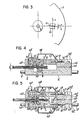
- each of the disk contacting surfaces 39 and 69 comprised head groups, 40 and 70, and each was mounted on a retractable support arm 22 or 52, via springs 42 or 72, but it is equally possible, as illustrated in cross-section in Figure 4, to have one of the disk contacting surfaces 69' comprising a non-active component 71' included simply to counteract the pressure of the opposing contacting surface 39' which comprises a head group 40' which is mounted in a support arm assembly 20' similar to either of those included in the above described embodiment, the non-active component 71' being mounted directly to the carriage 8' by adhesive bonding or a press fit, with only the head 40' retractably and adjustably mounted to a support arm 22' in a position adjustable support arm assembly 20', to provide a one side stationary- one side retractable magnetic head block assembly 6'.
- Parts in the figure which are similar to or correspond to those in Figures 1 and 2 are indicated by the same reference numerals, although these have been primed for clarity.
- a fixed contacting surface 69' is fitted by adhesive bounding or a press fit into a suitable receptacle 82' provided in the carriage 8'.
- a retractable magnetic head group 40' is adhesive bonded or press fit onto a support spring 42' which is bonded to or press fit into ridge portions 44' surrounding a depression 46', over which the head group 40' is fitted, in a support arm 22'.
- the support arm 22' is mounted via a cantilever spring 24' to an anchor member 28' to which the cantilever spring 24' is clamped by means of screws 18'.
- auxiliary pressure spring 38' which exerts additional pressure against the support arm 22' to normally urge it against the limiting stop or lip 36' provided on the frame 26' provided in cooperation with the anchor member 28'.
- a cross-piece 80' Integrally formed with or mechanically rigidly secured to the support arm 22' is a cross-piece 80' which can be suitably engaged to retract the support arm 22' and the head group 40' to allow the unobstructed insertion and removal of a floppy disk 1'.
- the support arm assembly 20' comprising the support arm 22' the cantilever and auxiliary springs 24' and 38', and the anchor member 28' and frame 26', is secured to the carriage 8' on a mounting surface 84' thereof, by means of screws 16' which can be loosened and retightened to adjust the position of the head group 40' by a method substantially the same as that described with regard to the preceding embodiment except that with this embodiment the position of the lower contacting surface 69' is not adjusted.
- FIG. 5 A third embodiment of a movable magnetic head block assembly for a floppy disck storage device according to this invention is illustrated in Figure 5.
- similar or corresponding parts to those in Figure 1 and 2 are denoted by the same reference numbers, but these have been double primed for clarity.
- the contacting surfaces 39" and 69" are each mounted on retractable support arms 22" and 52" mounted via cantilever springs 24" and 54" to anchor members 28" and 58" in support arm assemblies 20" and 50" which are largely similar to those employed in the first above described embodiment, illustrated in Figures 1 and 2.
- the anchor member 58" and associated frame 56" of the lower support arm assembly 50" is integral with the carriage portion which was separate in the embodiment illustrated in Figures 1 and 2, and it is provided with through holes 10" through which are passed rails on rods 12" over which the head assembly 6" slides in the radial direction of the floppy disk 1". Since the lower frame 56" is thus integral with the carriage, it is not possible to adjust the relative positions thereof.
- the relative position of the upper contact surface 39" is set according to the method described with respect to the first above described embodiment, the position of the lower contact surface 69" being adjusted approximately according to the same steps up to the step of tightening the cantilever and auxiliary spring securing screws 18".
- Other details and operations of this embodiment are the same as or similar to those described in relation to the first above mentioned embodiment.
- screws 16, 16' and 16" have been employed to secure the respective position adjustable support arm assemblies 20, 50, 20' and 20" to the respective surfaces 14, 15, 84', and 86" of the members 13, 8' and 58" to which they are fixed, with a view to enabling disassembly and readjustment at a later date.
- this facility may equally be considered to mechanically rigidly secure the respective members, once they have been set in their correct positions, by other means, such as adhesive bonding.
- this invention provides a construction wherein a head assembly including a pair of mutually opposed disk contacting surfaces, at least one of which comprises a magnetic head disposed to make resilient intimate contact with the surface of a magnetic disk while the opposite contacting surfaces applies a balancing tracking force to the directly opposite portion of the opposite side of the magnetic disk, the contacting surface comprising a magnetic head is fitted in a support arm assembly wherein the head is fixed via a resilient leaf spring to a retractable support arm, the support arm being provided at its one end with a flexible mounting means such as a cantilever leaf spring by which it is fixed to a rigid position adjustable anchor member, whereby the position of the magnetic head group supported therein can be suitably adjusted and set by a suitable known method, in relation to the rotational centre of the disk, and that position can be easily and accurately maintained, without requiring any special skill.
- a head assembly including a pair of mutually opposed disk contacting surfaces, at least one of which comprises a magnetic head disposed to make resilient intimate contact with the surface of a magnetic disk while the
Landscapes
- Supporting Of Heads In Record-Carrier Devices (AREA)
- Moving Of Heads (AREA)
Claims (6)
Applications Claiming Priority (2)
| Application Number | Priority Date | Filing Date | Title |
|---|---|---|---|
| JP55141548A JPS5766572A (en) | 1980-10-09 | 1980-10-09 | Magnetic head moving device of both-sided flexible disk storage device |
| JP141548/80 | 1980-10-09 |
Publications (2)
| Publication Number | Publication Date |
|---|---|
| EP0049943A1 EP0049943A1 (de) | 1982-04-21 |
| EP0049943B1 true EP0049943B1 (de) | 1984-06-06 |
Family
ID=15294521
Family Applications (1)
| Application Number | Title | Priority Date | Filing Date |
|---|---|---|---|
| EP81303740A Expired EP0049943B1 (de) | 1980-10-09 | 1981-08-17 | Bewegliche Magnetkopfanordnung für einen flexiblen doppelseitigen Plattenspeicher |
Country Status (4)
| Country | Link |
|---|---|
| US (1) | US4423449A (de) |
| EP (1) | EP0049943B1 (de) |
| JP (1) | JPS5766572A (de) |
| DE (1) | DE3163987D1 (de) |
Families Citing this family (27)
| Publication number | Priority date | Publication date | Assignee | Title |
|---|---|---|---|---|
| JPS58161177A (ja) * | 1982-03-19 | 1983-09-24 | Hitachi Ltd | 磁気ディスク装置 |
| JPS58224481A (ja) * | 1982-06-22 | 1983-12-26 | インタ−ナショナル ビジネス マシ−ンズ コ−ポレ−ション | デイスク装置の製造方法 |
| JPS5936371A (ja) * | 1982-08-23 | 1984-02-28 | Mitsubishi Electric Corp | フレキシブルデイスク記憶装置の磁気ヘツド移動装置 |
| DE8231126U1 (de) * | 1982-11-06 | 1983-04-07 | Robert Bosch Gmbh, 7000 Stuttgart | Magnetbandgeraet |
| NL8300133A (nl) * | 1983-01-14 | 1984-08-01 | Philips Nv | Inrichting voor het met behulp van een stralingsbundel inschrijven en/of uitlezen van informatie. |
| JPS6083255A (ja) * | 1983-10-12 | 1985-05-11 | Hitachi Ltd | 磁気記録装置の磁気ヘツド取付機構 |
| JPS60113360A (ja) * | 1983-11-24 | 1985-06-19 | Mitsubishi Electric Corp | 磁気デイスク装置 |
| US4599667A (en) * | 1984-03-12 | 1986-07-08 | Verbatim Corporation | Automatic azimuth angle adjustment head mounting structure |
| US4605979A (en) * | 1984-03-22 | 1986-08-12 | Hitachi, Ltd. | Load/unload suspension device for a magnetic disc apparatus |
| JPS60224110A (ja) * | 1984-04-20 | 1985-11-08 | Alps Electric Co Ltd | 磁気記録用装置 |
| JPS6177173A (ja) * | 1984-09-21 | 1986-04-19 | Canon Inc | 記録又は再生装置 |
| US4679105A (en) * | 1985-01-25 | 1987-07-07 | Maryatt Christopher J | Head positioning assembly for a disk drive |
| US4831615A (en) * | 1985-01-30 | 1989-05-16 | Nippon Columbia Co., Ltd. | Dual differential optical system moving apparatus |
| JPS61198479A (ja) * | 1985-02-27 | 1986-09-02 | Mitsubishi Electric Corp | 磁気ヘツド移動装置 |
| JPS6222267A (ja) * | 1985-07-23 | 1987-01-30 | Mitsubishi Electric Corp | 両面型フレキシブルデイスクのヘツド支持装置 |
| JPS6286591A (ja) * | 1985-10-14 | 1987-04-21 | Hitachi Ltd | 磁気ヘツドアツセンブリ− |
| US4731685A (en) * | 1985-10-16 | 1988-03-15 | Ampex Corporation | Transducing head mounting on an unsupported length of spring |
| US4703375A (en) * | 1985-11-22 | 1987-10-27 | Chan Industries, Inc. | Low mass tricomplaint recording device for double sided floppy disk media |
| US4740851A (en) * | 1986-04-21 | 1988-04-26 | Iomega Corporation | Disk drive with spicule member |
| US4794480A (en) * | 1986-04-21 | 1988-12-27 | Iomega Corporation | Bernoulli plate in cartridge |
| JP2572390B2 (ja) * | 1987-05-28 | 1997-01-16 | キヤノン電子株式会社 | デイスク装置 |
| US6600631B1 (en) * | 1989-11-27 | 2003-07-29 | Censtor Corp. | Transducer/flexure/conductor structure for electromagnetic read/write system |
| US20020176210A1 (en) * | 1989-11-27 | 2002-11-28 | Hamilton Harold J. | Durable, low-vibration, dynamic-contact hard disk drive system |
| US5041932A (en) * | 1989-11-27 | 1991-08-20 | Censtor Corp. | Integrated magnetic read/write head/flexure/conductor structure |
| US5111351A (en) * | 1989-11-27 | 1992-05-05 | Censtor Corp. | Integrated magnetic read/write head/flexure/conductor structure |
| JP2508955B2 (ja) * | 1992-04-20 | 1996-06-19 | ソニー株式会社 | 光磁気記録用摺動型磁気ヘッド |
| US5771139A (en) * | 1995-08-03 | 1998-06-23 | Phase Metrics | Integrated spring head/gimbal assembly holder |
Family Cites Families (17)
| Publication number | Priority date | Publication date | Assignee | Title |
|---|---|---|---|---|
| US3787644A (en) * | 1972-07-12 | 1974-01-22 | Digital Equipment Corp | Magnetic head adjustment assembly |
| JPS50123417A (de) * | 1974-03-18 | 1975-09-27 | ||
| US3975774A (en) * | 1974-12-04 | 1976-08-17 | Sycor, Inc. | Method and apparatus for loading flexible magnetic recording discs to transducing heads |
| US3946439A (en) * | 1975-01-31 | 1976-03-23 | International Business Machines Corporation | Recording apparatus for magnetic disks using both sides of the disk |
| USRE29380E (en) | 1975-01-31 | 1977-08-30 | International Business Machines Corporation | Recording apparatus for magnetic disks using both sides of the disk |
| JPS51102614A (ja) * | 1975-03-07 | 1976-09-10 | Hitachi Ltd | Fudogatajikihetsudokumitatetai |
| FR2309012A1 (fr) * | 1975-04-21 | 1976-11-19 | Ibm | Memoire a disque magnetique flexible |
| JPS5282321A (en) * | 1975-12-29 | 1977-07-09 | Kondo Masaki | Floating head unit |
| US4151573A (en) * | 1977-06-13 | 1979-04-24 | Tandon Magnetics Corp. | Magnetic recording device for double sided media |
| JPS5935112B2 (ja) * | 1977-10-19 | 1984-08-27 | 株式会社東芝 | 可撓性デスク駆動装置 |
| US4167766A (en) * | 1978-06-05 | 1979-09-11 | Ex-Cell-O Corporation | Flexible disk transducer loading and unloading system |
| US4306258A (en) * | 1978-06-26 | 1981-12-15 | Mitsubishi Denki Kabushiki Kaisha | Magnetic head supporting mechanism of double side type flexible disc drive apparatus |
| US4291350A (en) * | 1978-12-29 | 1981-09-22 | International Business Machines Corporation | Spring suspension for magnetic transducer |
| JPS5593564A (en) * | 1978-12-29 | 1980-07-16 | Ibm | Converter carriage assembly |
| JPS5857829B2 (ja) * | 1978-12-29 | 1983-12-22 | インタ−ナショナル ビジネス マシ−ンズ コ−ポレ−ション | 変換器支持装置 |
| US4253125A (en) * | 1979-03-19 | 1981-02-24 | Sperry Corporation | Head loading and unloading mechanism for magnetic flexible disk |
| US4328521A (en) * | 1980-04-07 | 1982-05-04 | Magnetic Peripherals Inc. | Gimbal spring retainer |
-
1980
- 1980-10-09 JP JP55141548A patent/JPS5766572A/ja active Pending
-
1981
- 1981-08-12 US US06/292,182 patent/US4423449A/en not_active Expired - Lifetime
- 1981-08-17 DE DE8181303740T patent/DE3163987D1/de not_active Expired
- 1981-08-17 EP EP81303740A patent/EP0049943B1/de not_active Expired
Also Published As
| Publication number | Publication date |
|---|---|
| JPS5766572A (en) | 1982-04-22 |
| EP0049943A1 (de) | 1982-04-21 |
| DE3163987D1 (en) | 1984-07-12 |
| US4423449A (en) | 1983-12-27 |
Similar Documents
| Publication | Publication Date | Title |
|---|---|---|
| US4423449A (en) | Movable magnetic head block assembly for a double sided flexible disk storage device | |
| JP4115526B2 (ja) | テープドライブにおけるアジマス記録のためのヘッド傾斜機構 | |
| US5162955A (en) | Apparatus for writing servo information onto a magnetic disk | |
| EP0381368B1 (de) | Festplattenlaufwerk mit Sicherheitswelle | |
| US4893205A (en) | Flexure mount for disc drives | |
| CN1177173A (zh) | 光盘机光学头调整装置 | |
| US4809106A (en) | Lead screw/transducer aligning mechanism for disk drive apparatus | |
| KR890004239B1 (ko) | 자기 디스크장치 | |
| KR900007479B1 (ko) | 기록 재생 장치의 헤드지지기구 | |
| US5146377A (en) | Adjustable magnetic head mounting system | |
| US4587587A (en) | Dual transducer assembly with linear adjustment | |
| US3825950A (en) | Magnetic card reader-recorder | |
| JPS58122674A (ja) | デイスク駆動装置におけるヘツドア−ムのためのピボツト支持構造 | |
| US4719692A (en) | Method of manufacturing a magnetic head assembly | |
| US5023735A (en) | Magnetic head support device with double gimbal structure | |
| EP0143443A2 (de) | Magnetplattenkopfgerät | |
| JPS60195718A (ja) | 磁気ヘツド装置 | |
| US4562501A (en) | Transducer support apparatus | |
| KR900007174B1 (ko) | 자기헤드 어셈블리 | |
| EP0160793A1 (de) | Optische Vorrichtung zur Ausrichtung von Wandlerköpfen | |
| TW408322B (en) | Disc reproduction apparatus | |
| EP0093886A2 (de) | Herstellungsverfahren und Gerät für die Justierung der Kopfposition in einem Gerät mit flexibler Platte | |
| KR19980068474U (ko) | 플로피디스크드라이브의 헤드 조정장치 | |
| GB2148409A (en) | Apparatus for positioning objects of low mass, in particular magnetic heads | |
| JPH0127130Y2 (de) |
Legal Events
| Date | Code | Title | Description |
|---|---|---|---|
| PUAI | Public reference made under article 153(3) epc to a published international application that has entered the european phase |
Free format text: ORIGINAL CODE: 0009012 |
|
| AK | Designated contracting states |
Designated state(s): DE FR GB |
|
| 17P | Request for examination filed |
Effective date: 19820329 |
|
| GRAA | (expected) grant |
Free format text: ORIGINAL CODE: 0009210 |
|
| AK | Designated contracting states |
Designated state(s): DE FR GB |
|
| REF | Corresponds to: |
Ref document number: 3163987 Country of ref document: DE Date of ref document: 19840712 |
|
| ET | Fr: translation filed | ||
| PLBE | No opposition filed within time limit |
Free format text: ORIGINAL CODE: 0009261 |
|
| STAA | Information on the status of an ep patent application or granted ep patent |
Free format text: STATUS: NO OPPOSITION FILED WITHIN TIME LIMIT |
|
| 26N | No opposition filed | ||
| PGFP | Annual fee paid to national office [announced via postgrant information from national office to epo] |
Ref country code: GB Payment date: 19920807 Year of fee payment: 12 Ref country code: FR Payment date: 19920807 Year of fee payment: 12 |
|
| PGFP | Annual fee paid to national office [announced via postgrant information from national office to epo] |
Ref country code: DE Payment date: 19920824 Year of fee payment: 12 |
|
| PG25 | Lapsed in a contracting state [announced via postgrant information from national office to epo] |
Ref country code: GB Effective date: 19930817 |
|
| GBPC | Gb: european patent ceased through non-payment of renewal fee |
Effective date: 19930817 |
|
| PG25 | Lapsed in a contracting state [announced via postgrant information from national office to epo] |
Ref country code: FR Effective date: 19940429 |
|
| PG25 | Lapsed in a contracting state [announced via postgrant information from national office to epo] |
Ref country code: DE Effective date: 19940503 |
|
| REG | Reference to a national code |
Ref country code: FR Ref legal event code: ST |