EP0049948B1 - Système de contrôle d'un moteur pour le positionnement d'un transducteur - Google Patents
Système de contrôle d'un moteur pour le positionnement d'un transducteur Download PDFInfo
- Publication number
- EP0049948B1 EP0049948B1 EP81304127A EP81304127A EP0049948B1 EP 0049948 B1 EP0049948 B1 EP 0049948B1 EP 81304127 A EP81304127 A EP 81304127A EP 81304127 A EP81304127 A EP 81304127A EP 0049948 B1 EP0049948 B1 EP 0049948B1
- Authority
- EP
- European Patent Office
- Prior art keywords
- stepper motor
- voltage
- current
- control system
- coupled
- Prior art date
- Legal status (The legal status is an assumption and is not a legal conclusion. Google has not performed a legal analysis and makes no representation as to the accuracy of the status listed.)
- Expired
Links
- 238000004804 winding Methods 0.000 claims description 54
- 239000003990 capacitor Substances 0.000 claims description 8
- 230000010355 oscillation Effects 0.000 description 17
- 230000007246 mechanism Effects 0.000 description 6
- 238000010586 diagram Methods 0.000 description 5
- 238000013016 damping Methods 0.000 description 3
- 230000009977 dual effect Effects 0.000 description 3
- 230000008901 benefit Effects 0.000 description 2
- 238000000034 method Methods 0.000 description 2
- 230000004044 response Effects 0.000 description 2
- 230000001133 acceleration Effects 0.000 description 1
- 230000003466 anti-cipated effect Effects 0.000 description 1
- 238000013459 approach Methods 0.000 description 1
- 230000008859 change Effects 0.000 description 1
- 238000010276 construction Methods 0.000 description 1
- 238000001816 cooling Methods 0.000 description 1
- 230000008878 coupling Effects 0.000 description 1
- 238000010168 coupling process Methods 0.000 description 1
- 238000005859 coupling reaction Methods 0.000 description 1
- 230000006872 improvement Effects 0.000 description 1
- 230000001939 inductive effect Effects 0.000 description 1
Images


Classifications
-
- G—PHYSICS
- G11—INFORMATION STORAGE
- G11B—INFORMATION STORAGE BASED ON RELATIVE MOVEMENT BETWEEN RECORD CARRIER AND TRANSDUCER
- G11B21/00—Head arrangements not specific to the method of recording or reproducing
- G11B21/02—Driving or moving of heads
- G11B21/08—Track changing or selecting during transducing operation
- G11B21/081—Access to indexed tracks or parts of continuous track
Definitions
- the present invention relates generally to open loop control systems for motors, particularly stepper motors, and more particularly to open loop control systems for stepper motors used in disk files and particularly where the stepper motor is utilized to position a transducer with respect to a record media.
- Disk files are in wide use for the storage and reproduction of signals on magnetic disk media. Such disk media have multiple parallel circular tracks.
- a movable transducer is mounted on a control arm and is capable of servicing a plurality of record tracks.
- a particular disk file may have a plurality of disk platters with each disk platter having two surfaces, both of which may be utilized.
- a particular disk file may even have multiple transducers per disk platter surface.
- the transducer movement with respect to the parallel circular tracks on a particular disk platter surface may be controlled by the use of a stepper motor. Upon command from a control unit, the stepper motor will move the transducer from one selected record track to another selected record track. This movement, consisting of acceleration and deceleration, is controlled by a system controller which knows which record track it is servicing and to which selected record track it is to be moved.
- power to the stepper motor may come from a programmed current high impedance source (sometimes called a "constant current” source), from a programmed voltage low impedance source (sometimes called a “constant voltage” source), or from a source with intermediate impedance characteristics.
- the programmed current source and the intermediate impedance source may be achieved in a variety of ways and are well known in the art.
- the programmed voltage source is not commonly used.
- One text which is especially helpful in explaining such drive systems is entitled Incremental Motion Control-Step Motors and Control Systems, edited by Benjamin C. Kuo, copyright 1979, published by S.R.L. Publishing Company, P. O. Box 2277, Station A, Champaigne, Illinois 61820. Of particular interest in this text is Chapter 4 relating to drive circuitry for stepper motors.
- Stepper motor control systems utilizing a programmed current source are advantageous because the rate at which the stepper motor current can be changed is very fast. This means that the rate at which the sequence of current values through which a stepper motor must be sequenced, during seek mode, can be made quite rapid. The rate is limited mainly by the voltage at which the programmed current source saturates since it is this voltage which sets the rate of charge and discharge of the stepper motor winding inductance.
- the stepper motor is controlled by a programmed current control source, a substantial time is required to damp these oscillations because no electronic damping is available.
- the time to damp this oscillation has been shown to be approximately 30 cycles of the basic motor/load resonant frequency.
- Some open loop control systems utilized for stepper motors used for positioning transducers use techniques to damp these inherent oscillations of the stepper motor. Techniques commonly used to damp stepper motors which are well known in the art are enumerated in Chapter 8 of Kuo's book.
- the mechanical dampers have the advantage of being insensitive to the phase of the oscillations occurring as the stepper motor reaches its last step, target record track, but suffer the disadvantage of high inertia, high cost, large size and poor reliability.
- the open loop electronic dampers suffer from the disadvantage of requiring timing which must be related to the phase of the oscillations occurring as the stepper motor reaches its last step. In fact, in random access positioning systems, considerable oscillations are present as the stepper reaches its last step. Furthermore, the phase of these oscillations depend on the number of steps, the prior speed profile, humidity and other factors making successful timing of the electronic dampers very difficult to achieve.
- the present invention concerns apparatus for positioning a transducer in relationship to a plurality of parallel tracks where the transducer is moveable between successive ones of the parallel tracks and where the position of the transducer is controlled by a motor.
- the motor is a stepper motor.
- a control system for a stepper motor having at least one phase winding for controlling the movement of said stepper motor in which said control system has a pulse width modulation control circuit operatively coupled to said phase winding and receiving as an input an error signal indicative of the positional error of said stepper motor; a current sensor coupled to said phase winding for producing a current feedback signal indicative of the current in said phase winding of said stepper motor; a voltage sensor coupled to said phase winding for producing a voltage feedback signal indicative of the voltage across said phase winding of said stepper motor; and a mode switch receiving said current feedback signal and said voltage feedback signal as inputs and having an output coupled to said error signal of said pulse width modulation control circuit, said mode switch operable to select between said current feedback signal and said voltage feedback signal; whereby said stepper motor may be operated in either current control mode utilizing said current sensor and said current error signal or in voltage control mode utilizing said voltage sensor and said voltage error signal.
- a current control system having a high output impedance for controlling the motor by supplying to the motor a programmable current relatively independent of instantaneous inductively and motionally induced emf (back emf) in the motor.
- a voltage control system is also utilized having a low output impedance for controlling the motor by supplying a programmable voltage relatively independent of instantaneous current in the motor.
- a switching system is also utilized for selecting the current control system when the transducer is making coarse adjustments in position relative to a selected one of the parallel tracks, and for selecting the voltage control system when the transducer is making fine adjustments in position relative to the selected one of the parallel tracks.
- the source presents a substantially zero impedance to the stepper motor, thereby allowing the motor to act as a generator with its own internal impedance as a load.
- the power developed by the generator causes the oscillations of the stepper motor to damp rapidly and independently of the phase of the oscillations at the last step. In one exemplary system, this dampening has occurred in approximately five to ten cycles.
- the programmed voltage source is inadequate to increment the stepper motor at high speeds because the rate of charge of current in the stepper motor is not fast.
- Both control modes (current and voltage) use a pulse width modulated power driver to increase efficiency and to minimize the total power variations as the motor operates in seek mode. The relatively small power variations minimize the variations in temperature occurring in the disk drive thereby improving the positioning accuracy of the transducer.
- the system is particularly useful where there is seamless switchover between the current control system and the voltage control system. This is achieved where the voltage control system has a characteristic time constant consisting substantially of a resistance R v times a capacitance C, where the motor has a characteristic time constant consisting substantially of an inductance L divided by a resistance R m , and where the value of R v C is substantially equal to the value of UR m thereby achieving the seamless switchover.
- the voltage control system looks to the stepper motor as an approximate zero impedance.
- the limitation then on time to dissipate the back emf induced in the phase windings of the stepper motor is the internal resistance of the stepper motor itself, generally comprising the resistance of the stator windings.
- an impedance canceling system also may be coupled into the voltage control system feedback loop to provide a driving impedance to the stepper motor of a magnitude which is exactly equal to and has a phase which is exactly opposite to the magnitude and phase of the internal stalled impedance of the phase windings of the stepper motor itself.
- the damping time for the back emf created the stepper motor windings is made even shorter.
- An exemplary system damps the oscillations within three to four cycles, independent of the phase of the oscillations at the last step.
- the response time of a disk file utilizing the transducer is made faster.
- the response time of the disk file is shortened as the time in which a predetermined degree of positioning accuracy in the transducer with respect to the target record track is achieved is made shorter.
- Figure 1 illustrates a magnetic disk platter 10 being rotated around a spindle 12 and having a plurality of circular parallel record tracks.
- Two exemplary record tracks (14 and 16) are shown in Figure 1 for descriptive purposes.
- a transducer 18 is shown positioned properly with respect to track 14 and is mounted on a transducer positioning mechanism 20.
- the transducer positioning mechanism 20 is driven by a stepper motor (not shown).
- the stepper motor is sequenced so that the transducer 18 is accelerated inward from track 14 and then decelerated to the dotted 18A position at track 16 supported by transducer positioning mechanism 20A.
- Track 16 in this example, would be the target track.
- the transducer 18 would be moving in seek mode from its position represented by reference numeral 18 on track 14 to a position near that position represented by reference numeral 18A aligned with track 16. As the transducer 18 is damped and holds track 16, detent mode is achieved. When the transducer 18 is seeking and accelerating from track 14 toward track 16 it is making a coarse position adjustment. As transducer 18 approaches track 16 and decelerates and is damped to be positioned on track 16, it is making fine adjustments in position.
- Figure 2 represents a block diagram of the dual mode control for the phase windings of the stepper motor. Only one phase winding 22 is illustrated in Figure 1. While it is anticipated that a given stepper motor will have a plurality of windings, and in a preferred embodiment it has two phase windings, the control system for each phase winding is identical. Therefore, the control system for controlling one phase winding 22 will be described in detail with the understanding that it is equally applicable to all other phase windings.
- a programmed current signal on line 24 is supplied from an external source (a system controller, not shown) to represent the particular current program to be supplied to this particular phase winding 22 in order to move the stepper motor or to sequence the stepper motor the proper step or number of steps to reach the selected target track.
- a closed loop feedback system in the prior art may include either a current sensor or a voltage sensor coupled from the phase winding 22 back to input line 24 providing an input to the pulse width modulation circuit 26.
- a current sensor 28 is provided to sense the current present in phase winding 22 and to feedback that indication through mode switch 30 to input 24 to pulse width modulation circuit 26.
- the system in Figure 2 also includes a voltage sensor 32 coupled across phase winding 22 to supply feedback from phase winding 22 to the pulse width modulation circuit 26. Mode switch 30 may then select from either the current sensor 28 or the voltage sensor 32 to supply either constant current feedback or constant voltage feedback respectively.
- the particular current supplied on input line 24 and the mode of feedback control is under the control of a system controller (not shown) which is outside the scope of the present invention.
- the system controller knows where the stepper motor is located and through what steps the stepper motor needs to sequence in order for the transducer to reach the- selected target track and it knows when the stepper motor is making coarse adjustments in position and when it is making fine adjustments in position. It is within the scope of the present invention to provide the capability to the system controller for having both modes of operation and the ability to switch between them.
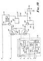
- FIGS 3a and 3b provide a schematic diagram of the feedback control loop.
- FIGs 3a and 3b provide a schematic diagram of the feedback control loop.
- These figures illustrate the phase winding 22 shown at the center right of Figure 3a, the current sensor 28 shown in the dashed box in the lower left of Figure 3a, the voltage sensor shown in the dashed box at the lower left of Figure 3b and the mode switch shown at center left of Figure 3a. All of the remaining circuitry in both figures 3a and 3b represent the pulse width modulation circuit 26.
- the pulse width modulation circuit shown is exemplary of those well known in the art.
- Control circuit 100 operates through transistors 102, 104, 106, 108 and switching transistors 110, 112, 114, 116, to provide pulse width modulation switching to the phase winding 22 of the stepper motor. Miscellaneous components 118 through 138 and 142 through 196 complete the-circuit of this well-known pulse width modulation control circuit.
- Current sensor 28 in Figure 3a operates as a difference amplifier by taking the difference in the current present through the collector of transistor 112 and the collector of transistor 116 with these points measuring the current through the phase winding 22.
- the difference between the currents present in the collector of transistor 112 and the collector of transistor 116 quite accurately represents the current in the motor.
- the signals are then supplied through resistors 202, 204, 206 and 208 and capacitors 210 and 212 to operational amplifier 214 operating as a difference amplifier with resistors 216, 218 and capacitor 220.
- the output of the current sensor is then supplied through feedthrough resistor 222 to input 224 of mode switch 30.
- the system controller selects terminal 224 of mode switch 30, or in other words selects current sensor 28, the resulting signal supplied to pulse width modulation control circuit 100 through line 24, resistors 226, 228 and capacitor 230 represents a signal indicative of the current flowing through the phase winding 22.
- voltage sensor 32 When terminal 232 of mode switch 30 is selected, voltage sensor 32 is coupled in the feedback loop to the pulse width modulation control circuit 100. Voltage sensor 32 is coupled directly across phase winding 22 through resistors 234, 236, 238, 240, and 241 and capacitors 242 and 244. Operational amplifier 246 operates as a subtractor in conjunction with resistors 248 and 250. The resulting output of operational amplifier 246 then is a signal directly indicative of the voltage across the phase winding 22. When terminal 232 of the mode switch 30 is selected, the voltage sensor 32 is coupled in the feedback loop. Because of the heavy voltage feedback the output impedance is relatively small.
- This low output impedance then enables the back emf generated by the oscillations of the stepper motor to be dissipated through a low impedance resulting in a small mechanical time constant due to the low output resistance. This results in a short decay time of the oscillations.
- an impedance cancelling circuit to the output of the current sensor 28 and the voltage sensor 32.
- an operational amplifier 252 is coupled to the output of the operational amplifier 214 through resistor 254.
- the positive input to operational amplifier 252 is coupled to ground.
- Operational amplifier 252 with resistor 256 and capacitor 258 acts as a phase inverter with a gain of minus one.
- the output of operational amplifier 252 is coupled through capacitor 260 to block DC and through feedthrough resistor 262 to the output of voltage sensor 32.
- This network operates as an impedance canceling circuit by providing a positive current feedback via a generalized impedance which blocks direct current but otherwise matches the impedance (both resistance and inductive reactance) of the phase winding 22.
- the operational amplifier 252 has a gain of minus one. This provides, at a relatively low operating frequency, in a preferred embodiment approximately 200 hertz corresponding to the stepper motor and load resonant frequency, a positive feedback path which in conjunction with the negative voltage feedback creates a driving impedance exactly opposite that of the impedance of the phase winding 22.
- this impedance canceling circuit when this impedance canceling circuit is coupled in the feedback loop of the pulse width modula-' tion control circuit 100, its impedance matches and cancels the impedance of phase winding 22.
- any back emf motionally induced in phase winding 22 may be quickly clamped through an essentially net zero impedance. This is because the impedance canceling circuit effectively compensates for the internal impedance of the phase winding 22 with the result of a net zero impedance. This results in an extremely short mechanical time constant and a very short decay time for such back emf.
Landscapes
- Control Of Stepping Motors (AREA)
Claims (9)
Applications Claiming Priority (2)
| Application Number | Priority Date | Filing Date | Title |
|---|---|---|---|
| US197184 | 1980-10-15 | ||
| US06/197,184 US4383209A (en) | 1980-10-15 | 1980-10-15 | Control system for transducer positioning motor |
Publications (3)
| Publication Number | Publication Date |
|---|---|
| EP0049948A2 EP0049948A2 (fr) | 1982-04-21 |
| EP0049948A3 EP0049948A3 (en) | 1982-12-01 |
| EP0049948B1 true EP0049948B1 (fr) | 1986-05-28 |
Family
ID=22728385
Family Applications (1)
| Application Number | Title | Priority Date | Filing Date |
|---|---|---|---|
| EP81304127A Expired EP0049948B1 (fr) | 1980-10-15 | 1981-09-09 | Système de contrôle d'un moteur pour le positionnement d'un transducteur |
Country Status (8)
| Country | Link |
|---|---|
| US (1) | US4383209A (fr) |
| EP (1) | EP0049948B1 (fr) |
| JP (1) | JPS5795199A (fr) |
| AU (1) | AU7632381A (fr) |
| BR (1) | BR8106632A (fr) |
| CA (1) | CA1171524A (fr) |
| DE (1) | DE3174716D1 (fr) |
| ZA (1) | ZA817116B (fr) |
Cited By (1)
| Publication number | Priority date | Publication date | Assignee | Title |
|---|---|---|---|---|
| CN103605399A (zh) * | 2013-11-21 | 2014-02-26 | 张辉兵 | 一种双控开关及其控制方法 |
Families Citing this family (22)
| Publication number | Priority date | Publication date | Assignee | Title |
|---|---|---|---|---|
| US4600868A (en) * | 1983-05-09 | 1986-07-15 | Bryant Lawrence M | Open loop acceleration/deceleration control for disk drive stepper motors |
| JPS60127576A (ja) * | 1983-12-15 | 1985-07-08 | Mitsubishi Electric Corp | 磁気デイスク装置 |
| JPS60170078A (ja) * | 1984-02-10 | 1985-09-03 | Teac Co | デイスク装置 |
| JPH063994B2 (ja) * | 1984-10-05 | 1994-01-12 | 株式会社日立製作所 | 複数台デイジタルサーボの制御方法 |
| JPS6198186A (ja) * | 1984-10-17 | 1986-05-16 | Mitsubishi Electric Corp | インバ−タ装置の位置決め割り出し制御方式 |
| US4602197A (en) * | 1985-01-14 | 1986-07-22 | Xebec | Stepping motor control system |
| IT1182420B (it) * | 1985-02-08 | 1987-10-05 | Olivetti & Co Spa | Apparecchiatura per registrare e leggere informazioni su un disco magnetico |
| US4751441A (en) * | 1985-05-31 | 1988-06-14 | Cambrian Consultants, Inc. | Transducer position control system for disk storage equipment |
| GB2188720B (en) * | 1986-04-04 | 1990-12-19 | Data Recording Instr Co | Improved position control system |
| JPS6426390A (en) * | 1987-07-20 | 1989-01-27 | Shinko Electric Co Ltd | Operating method for pulse motor |
| CH672043B5 (fr) * | 1988-02-12 | 1990-04-30 | Ebauchesfabrik Eta Ag | |
| JPH08251992A (ja) * | 1995-03-15 | 1996-09-27 | Alps Electric Co Ltd | ステッピングモータ駆動装置 |
| BR9713800A (pt) | 1996-12-31 | 2000-02-01 | Reckitt & Colmann Prod Ltd | Composição de limpeza abrasiva aquosa antibacteriana. |
| US5986426A (en) * | 1997-08-05 | 1999-11-16 | International Business Machines Corporation | Adaptive pulse width modulated motor control |
| DE19928356C1 (de) * | 1999-06-21 | 2000-12-07 | Sig Positec Bergerlahr Gmbh & | Verfahren zum Positionieren eines Schrittmotors und elektrischen Antriebs |
| JP3524848B2 (ja) * | 2000-07-14 | 2004-05-10 | ローム株式会社 | モータ駆動装置及びこれを用いたディスク装置 |
| DK1454609T3 (da) * | 2003-03-05 | 2013-02-11 | Csl Behring Gmbh | Overføringsindretning |
| DE10314724A1 (de) * | 2003-03-31 | 2004-11-04 | Demag Cranes & Components Gmbh | Verfahren zum Vermindern des Polygoneffekts bei einem Kettentrieb, insbesondere bei einem Kettenzug, und Kettentrieb hierfür |
| US7112937B1 (en) * | 2005-10-31 | 2006-09-26 | Hewlett-Packard Development Company, Lp. | Device and method for driving a motor |
| CN101411053B (zh) * | 2006-03-31 | 2011-09-28 | Thk株式会社 | 交流电动机驱动装置以及控制方法 |
| CN111026029B (zh) * | 2019-12-25 | 2023-07-07 | 深圳市恒控科技有限公司 | 一种校准数控设备电机轴的装置、方法及系统 |
| US12143056B2 (en) * | 2021-08-31 | 2024-11-12 | Texas Instruments Incorporated | Current regulation for stepper motors using dual loop control through voltage mode and current mode |
Family Cites Families (21)
| Publication number | Priority date | Publication date | Assignee | Title |
|---|---|---|---|---|
| US3706857A (en) * | 1971-01-05 | 1972-12-19 | Ibm | Disk cartridge with rotatably adjustable head |
| US3860861A (en) * | 1971-12-27 | 1975-01-14 | Potter Instrument Co Inc | Disk drive head positioning servo including temperature responsive safety means |
| DE2258382A1 (de) | 1972-11-29 | 1974-06-06 | Ibm Deutschland | Regeleinrichtung zur steuerung der bewegung eines einstellelementes |
| JPS5033410A (fr) * | 1973-08-03 | 1975-03-31 | ||
| US3974434A (en) * | 1974-03-08 | 1976-08-10 | Electronic Engineering Company Of California | Stepping motor signal circuit |
| US3994016A (en) * | 1975-03-31 | 1976-11-23 | Honeywell Information Systems, Inc. | Head positioning servo system for disk drives |
| GB1503972A (en) * | 1975-07-24 | 1978-03-15 | Ibm | Data storage apparatus |
| DE2558359A1 (de) * | 1975-12-23 | 1977-07-07 | Ibm Deutschland | Einstellvorrichtung fuer den zugriffsarm des magnetkopfes eines magnetplattenspeichers |
| US4092682A (en) * | 1976-08-10 | 1978-05-30 | Sperry Rand Corporation | Cross coupled demodulator for generating a servo head position error signal |
| US4101942A (en) * | 1976-10-15 | 1978-07-18 | Xerox Corporation | Track following servo system and track following code |
| US4130844A (en) * | 1976-10-26 | 1978-12-19 | Xerox Corporation | Method and means for tracking magnetic tracks |
| US4135217A (en) * | 1976-11-02 | 1979-01-16 | Xerox Corporation | Utilization of stored run-out information in a track following servo system |
| GB1516239A (en) * | 1976-12-09 | 1978-06-28 | Burroughs Corp | Positioning system and method particularly useful for magnetic disc drives |
| GB1520350A (en) * | 1976-12-22 | 1978-08-09 | Ibm | Data storage apparatus |
| US4096534A (en) * | 1977-04-12 | 1978-06-20 | International Business Machines Corporation | Track accessing circuitry for a disk file with switchable filter |
| US4096533A (en) * | 1977-04-28 | 1978-06-20 | International Tapetronics Corporation | Cartridge tape transport which accommodates single or dual capstan cartridges |
| US4125882A (en) * | 1977-06-23 | 1978-11-14 | Persci, Inc. | Disc file system with improved seek control |
| GB2023893B (en) | 1978-06-21 | 1982-12-22 | Data General Corp | Stepping motor excitation circuitry |
| JPS584362B2 (ja) * | 1979-01-19 | 1983-01-26 | 富士通株式会社 | 位置決め方式 |
| DD142777B1 (de) * | 1979-04-03 | 1984-12-05 | Riessland Eberhard Dipl Ing | Schaltungsanordnung zur verlustarmen ansteuerung von elektromagnetischen schrittantriebssystemen |
| US4277732A (en) * | 1979-08-03 | 1981-07-07 | Graphtek, Inc. | Low power stepping motor driver circuit and method |
-
1980
- 1980-10-15 US US06/197,184 patent/US4383209A/en not_active Expired - Lifetime
-
1981
- 1981-09-03 CA CA000385152A patent/CA1171524A/fr not_active Expired
- 1981-09-09 EP EP81304127A patent/EP0049948B1/fr not_active Expired
- 1981-09-09 DE DE8181304127T patent/DE3174716D1/de not_active Expired
- 1981-10-14 JP JP56164041A patent/JPS5795199A/ja active Pending
- 1981-10-14 AU AU76323/81A patent/AU7632381A/en not_active Abandoned
- 1981-10-14 ZA ZA817116A patent/ZA817116B/xx unknown
- 1981-10-14 BR BR8106632A patent/BR8106632A/pt unknown
Cited By (1)
| Publication number | Priority date | Publication date | Assignee | Title |
|---|---|---|---|---|
| CN103605399A (zh) * | 2013-11-21 | 2014-02-26 | 张辉兵 | 一种双控开关及其控制方法 |
Also Published As
| Publication number | Publication date |
|---|---|
| DE3174716D1 (en) | 1986-07-03 |
| BR8106632A (pt) | 1982-06-29 |
| ZA817116B (en) | 1982-11-24 |
| AU7632381A (en) | 1982-04-22 |
| EP0049948A3 (en) | 1982-12-01 |
| CA1171524A (fr) | 1984-07-24 |
| EP0049948A2 (fr) | 1982-04-21 |
| US4383209A (en) | 1983-05-10 |
| JPS5795199A (en) | 1982-06-12 |
Similar Documents
| Publication | Publication Date | Title |
|---|---|---|
| EP0049948B1 (fr) | Système de contrôle d'un moteur pour le positionnement d'un transducteur | |
| US4030132A (en) | Dual mode velocity servo control for a linear actuator motor | |
| JP3089709B2 (ja) | 磁気ディスク装置のアクセスサーボ機構 | |
| Yi et al. | Two-degree-of-freedom control with robust feedback control for hard disk servo systems | |
| US6014285A (en) | Positioning control system | |
| KR930009998B1 (ko) | 변환기의 위치 결정 제어방식 | |
| CA1219070A (fr) | Dispositif et methode de positionnement a asservissement | |
| US6493177B1 (en) | Microactuator assisted seek and hysteresis correction method and apparatus for a disk drive | |
| IE52943B1 (en) | Method and apparatus for controlling a stepper motor | |
| US4796112A (en) | Actuator access control system for a magnetic head using trapezoidal drive current | |
| US5062023A (en) | Disk file servo loop with improved track settling | |
| US5781362A (en) | Servo control system for driving a voice coil motor with pulse width and gain control | |
| KR20010111510A (ko) | 디스크 드라이브에 있어서 자체 튜닝 모델 참조 컨트롤러 | |
| US5258966A (en) | Positioner seek control system of a disk apparatus and method for scanning a beam across a medium | |
| US4616277A (en) | Disk drive storage system having means for compensating for seek driving forces coupled between head actuators | |
| JPS5947985A (ja) | サ−ボモ−タの速度制御方式 | |
| US4566046A (en) | Positioning apparatus for a magnetic head of a magnetic disk drive apparatus | |
| JPH01253881A (ja) | 磁気ヘッド位置決め速度制御方式 | |
| JP2770729B2 (ja) | ヘッドアクセス制御方法 | |
| JPH01171173A (ja) | 位置決め制御方式 | |
| JPS6166267A (ja) | トラツクアクセス装置 | |
| JPH0243271B2 (fr) | ||
| Hu | On high-performance servo control algorithms for hard disk drive | |
| JP2616415B2 (ja) | 磁気ディスク装置 | |
| JPH02304782A (ja) | 磁気デイスク装置の制御方法 |
Legal Events
| Date | Code | Title | Description |
|---|---|---|---|
| PUAI | Public reference made under article 153(3) epc to a published international application that has entered the european phase |
Free format text: ORIGINAL CODE: 0009012 |
|
| AK | Designated contracting states |
Designated state(s): DE FR GB IT |
|
| PUAL | Search report despatched |
Free format text: ORIGINAL CODE: 0009013 |
|
| AK | Designated contracting states |
Designated state(s): DE FR GB IT |
|
| RHK1 | Main classification (correction) |
Ipc: G11B 5/55 |
|
| 17P | Request for examination filed |
Effective date: 19830506 |
|
| GRAA | (expected) grant |
Free format text: ORIGINAL CODE: 0009210 |
|
| AK | Designated contracting states |
Kind code of ref document: B1 Designated state(s): DE FR GB IT |
|
| ITF | It: translation for a ep patent filed | ||
| REF | Corresponds to: |
Ref document number: 3174716 Country of ref document: DE Date of ref document: 19860703 |
|
| ET | Fr: translation filed | ||
| PLBE | No opposition filed within time limit |
Free format text: ORIGINAL CODE: 0009261 |
|
| STAA | Information on the status of an ep patent application or granted ep patent |
Free format text: STATUS: NO OPPOSITION FILED WITHIN TIME LIMIT |
|
| 26N | No opposition filed | ||
| REG | Reference to a national code |
Ref country code: GB Ref legal event code: 732 |
|
| PGFP | Annual fee paid to national office [announced via postgrant information from national office to epo] |
Ref country code: FR Payment date: 19890823 Year of fee payment: 9 |
|
| PGFP | Annual fee paid to national office [announced via postgrant information from national office to epo] |
Ref country code: DE Payment date: 19890828 Year of fee payment: 9 |
|
| PGFP | Annual fee paid to national office [announced via postgrant information from national office to epo] |
Ref country code: GB Payment date: 19890831 Year of fee payment: 9 |
|
| ITTA | It: last paid annual fee | ||
| PG25 | Lapsed in a contracting state [announced via postgrant information from national office to epo] |
Ref country code: GB Effective date: 19900909 |
|
| GBPC | Gb: european patent ceased through non-payment of renewal fee | ||
| PG25 | Lapsed in a contracting state [announced via postgrant information from national office to epo] |
Ref country code: FR Effective date: 19910530 |
|
| PG25 | Lapsed in a contracting state [announced via postgrant information from national office to epo] |
Ref country code: DE Effective date: 19910601 |
|
| REG | Reference to a national code |
Ref country code: FR Ref legal event code: ST |