EP0051282B1 - Objektiv grosser Apertur - Google Patents
Objektiv grosser Apertur Download PDFInfo
- Publication number
- EP0051282B1 EP0051282B1 EP81109246A EP81109246A EP0051282B1 EP 0051282 B1 EP0051282 B1 EP 0051282B1 EP 81109246 A EP81109246 A EP 81109246A EP 81109246 A EP81109246 A EP 81109246A EP 0051282 B1 EP0051282 B1 EP 0051282B1
- Authority
- EP
- European Patent Office
- Prior art keywords
- lens
- objective lens
- disc
- recording
- laser beam
- Prior art date
- Legal status (The legal status is an assumption and is not a legal conclusion. Google has not performed a legal analysis and makes no representation as to the accuracy of the status listed.)
- Expired
Links
- 230000003287 optical effect Effects 0.000 claims abstract description 10
- 239000011521 glass Substances 0.000 claims description 3
- 230000003595 spectral effect Effects 0.000 abstract description 2
- 239000002131 composite material Substances 0.000 description 5
- 230000004075 alteration Effects 0.000 description 2
- 230000001427 coherent effect Effects 0.000 description 2
- 238000000034 method Methods 0.000 description 2
- 238000002485 combustion reaction Methods 0.000 description 1
- 230000000694 effects Effects 0.000 description 1
- 238000010309 melting process Methods 0.000 description 1
- 239000006223 plastic coating Substances 0.000 description 1
- 238000011084 recovery Methods 0.000 description 1
- 238000002310 reflectometry Methods 0.000 description 1
Images


Classifications
-
- G—PHYSICS
- G02—OPTICS
- G02B—OPTICAL ELEMENTS, SYSTEMS OR APPARATUS
- G02B9/00—Optical objectives characterised both by the number of the components and their arrangements according to their sign, i.e. + or -
- G02B9/34—Optical objectives characterised both by the number of the components and their arrangements according to their sign, i.e. + or - having four components only
-
- G—PHYSICS
- G02—OPTICS
- G02B—OPTICAL ELEMENTS, SYSTEMS OR APPARATUS
- G02B13/00—Optical objectives specially designed for the purposes specified below
- G02B13/24—Optical objectives specially designed for the purposes specified below for reproducing or copying at short object distances
Definitions
- This invention relates generally to objective lenses, and, more particularly. to objective lenses used in the recording and playback of signals recorded optically on rotatable discs.
- information may be recorded on an information track on a disc by means of a modulated laser beam.
- the information track takes the form of a series of pits in the disc surface.
- a playback laser beam is directed onto the surface, the information is retrieved from the information track, since the playback beam is selectively reflected by the presence or absence of pits in the surface.
- This technique is generally well known in the video recording field, and may also be used for the storage and retrieval of digital information, such as may be used in conjunction with a computer system.
- the information is recorded on the disc either in a spiral track or in a plurality of concentric circular tracks on the disc surface.
- means must be provided for focussing the laser beam onto the disc surface in a spot size of the order of one micron in diameter.
- the focused laser beam must have sufficient power to effect the necessary deformation of the surface, typically by means of a controlled combustion or melting process. Accordingly, a relatively high numerical aperture objective lens is desirable for this application.
- the working distance or clearance between the lens and the recording surface needs to be great enough to minimize the possibility of inadvertent contact with the disc surface.
- an objective lens with the desirable characteristics of high numerical aperture and relatively large working distance, such a lens would typically be bulky and massive.
- another requirement for an objective lens used in the recording of information on a disc is that the total mass of the lens be minimized, to facilitate rapid movement of the lens both in a radial direction, to move from one information track to another and to automatically align with a given information track, and in a direction perpendicular to the disc surface, to ensure automatic focusing of the beam.
- lasers typically used for recording in such systems such as argon-ion lasers
- the laser beam could be filtered to provide a monochromatic source, this would substantially reduce the total power of the beam and would therefore necessitate a laser of substantially higher power for recording purposes.
- the objective lens used to focus the beam on the disc surface should ideally be color corrected to provide a properly focussed beam over a range of frequencies including those generated by the laser.
- a read and write objective lens for recovery and encoding of information upon a storage member is known by EP-B-17466.
- the working distance of this objective lens is considered too short. Besides of that the overall length and the total mass is considered too large to accomplish automatic focussing efficiently.
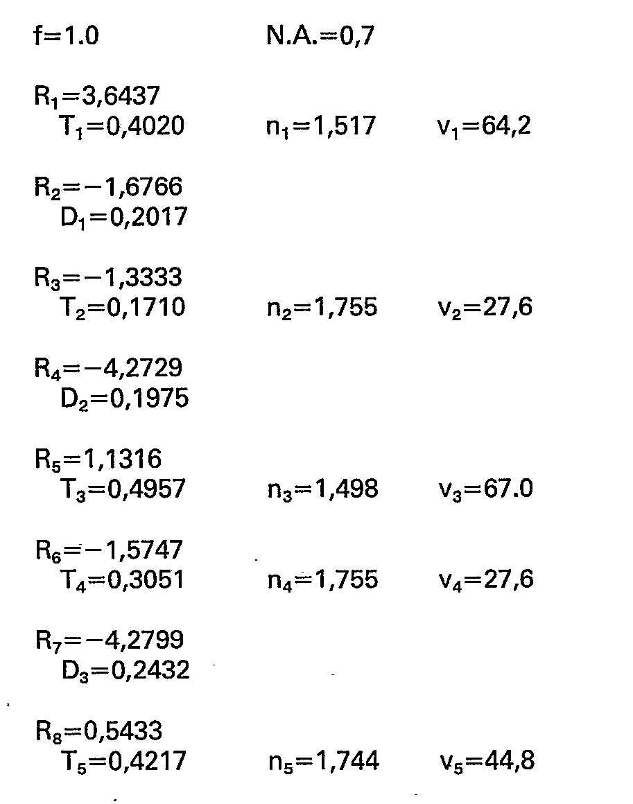
- the present invention resides in an objective lens having five elements which have the numerical data as recited in claim 1 or 3.
- This fifth elements of the objective lenses according to the invention cooperate with a sixth element having optically flat parallel surfaces and thickness of approximately 1.2 millimeters.
- This sixth element is a plastic coating formed over a disc on which information is to be recorded.
- the focal point at which the laser beam converges is located at the plane of contact between this sixth optical element and the recording surface of the disc.
- the weight of the composite lens is approximately four grams.
- the lens is color corrected to provide a desirably small composite aberration characteristic for wavelengths of 476.5 nanometers (nm), 488.0 nm, and 496.5 nm.
- the present invention provides an ideal objective lens for use in recording of information on a disc.
- it combines a high numerical aperture, low total mass, shorter overall length, relatively large working distance, and displays minimal optical aberration, as measured by the optical path difference, over a range of wavelengths.
- the present invention relates to an objective lens intended for use in an optical recording system in which a light beam from a laser is focused onto a recording track surface and is modulated in such a manner as to cause selective deformation of the surface.
- the resulting deformations in the recording surface are representative of the information signal, which may be later reproduced from the disc by means of another laser beam.
- the information signal is recreated as a result of the variations in reflectivity of the disc surface along the recording track.
- Recording systems of this general type may be used to store digital information as part of a large and infrequently changed data base.
- the recording beam in such a system is focused onto the recording track through an objective lens, which must have certain ideal properties if the recording process is to be carried out in an efficient manner.
- the lens must be capable of focusing a relatively large diameter coherent light beam into a small point of light of approximately one micron in diameter. Coupled with this, the total lens mass must be low, to allow for rapid movements of the lens to make automatic focus adjustments, and the working distance or clearance between the lens and the disc must be large enough to minimize the risk of contact between the two.
- the lens should be color corrected to accommodate the range of spectral frequencies contained within the laser beam, so that maximum power may be provided in the focused recording beam.
- the composite objective lens indicated generally by reference numeral 10 in Fig. 1 comprises five lens elements 11-15, respectively, where lens element 11 is located at the ray entrance side of the lens (the left side as viewed in Fig. 1), and is the element through which light from a laser light source (not shown) first enters.
- the first element 11 is of positive power and has convex outer surfaces of radius R 1 and R 2 , respectively, as indicated in the drawings, and has a thickness T 1 measured at the central axis of the lens.
- the second lens element 12 Spaced from the first lens element 11 by a distance D 1 is the second lens element 12, of thickness T 2 , the left-hand radius of which is R 3 and the right-hand radius of which is R 4 , the first radius R 3 providing a concave surface and the second radius R 4 providing convex surface.
- the third lens element 13 is spaced by a distance D 2 from the second lens element 12 and has a thickness T 3 , a left-hand convex radius R s and a right-hand convex radius R 6 , the latter defining a convex surface in contact with a corresponding concave surface of the fourth lens element 14.
- Element 14 has a thickness T 4 and a right-hand radius R 7 defining a slightly convex surface.
- the fifth lens element 15 is spaced by a distance D 3 from lens element 14, and has a thickness T s , a left-hand radius R 8 defining a convex surface on the right-hand side of the lens element.
- the fifth lens element 15 is spaced by a distance d 4 from a sixth element 16 having parallel sides of infinite radius and representing a clear plastic layer over the recording surface of a recording disc (not shown). As shown by the outer light rays in the figure, the light beam is focussed on the inner surface 20 of the plastic layer 16.
- the composite objective lens system shown in Fig. 1 has a desirably high numerical aperture of 0.7, a working distance of approximately two millimeters, this being the distance D 4 , and a relatively low mass of only approximately four grams. Moreover, as shown in Figs. 2-7, the optical path difference never exceeds approximately one half of a wavelength for any of the three wavelengths for which the aberrational characteristics were recorded.
- Figs. 2-4 show in conventional form the variation in the path length difference, measured in wavelengths along the Y axis, with respect to various locations in the tangential plane.
- Fig. 2 gives the aberrational curves for a relative field height of 1.00 (or 0.23° half-angle)
- Fig. 3 provides the corresponding information for a relative field height of 0.71 (0.16° half-angle)
- Fig. 4 provides the corresponding information for a relative field height of zero.
- Figs. 5-7 show the corresponding path length differences in the sagittal plane, for field heights of 1.0, 0.71 and zero, respectively.
- Figs. 2-7 and 9-14 the broken line plots the path length difference for a wavelength of 476.5 nm, the solid line corresponds to a wavelength of 488.0 nm, and the dotted line corresponds to a wavelength of 496.5 nm.
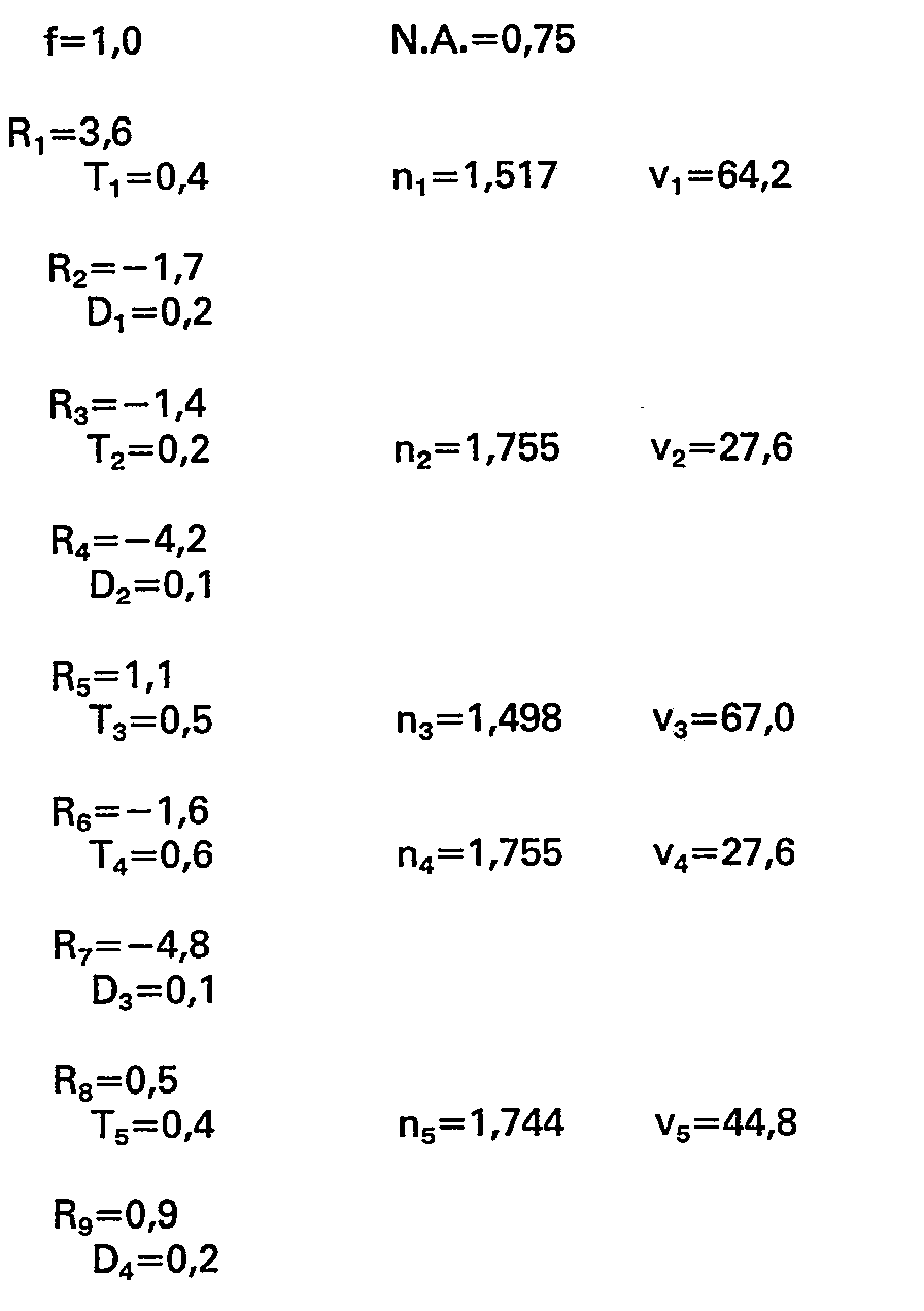
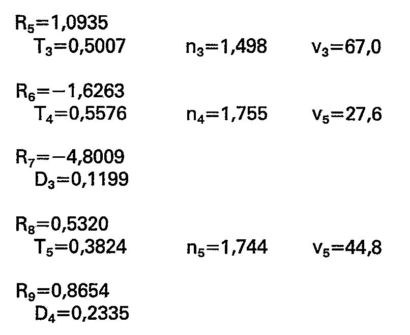
- Fig. 8 shows a second embodiment of the invention, in which the lens elements have been designated 11'-15' to distinguish them from the elements shown n Fig. 1. The data are as follows:
- the composite lens has a numerical aperture of 0.75 and a working distance of approximately two millimeters.
- the aberrational data given in Figs. 9-14 showthatthe path length difference never exceeds approximately one-sixth of a wavelength for the three wavelengths under consideration.
- the arrangement of Figs. 9-14 corresponds to that of Figs. 2-7.
- Figs. 9-11 show the path length differences in the tangential plane for relative field heights of 1.0, 0.71 and zero, respectively, and Figs. 12-14 give the corresponding sagittal plane information.
- the plastic layer 16 with which the lens of the invention cooperates has refractive indices of 1.4985, 1.4977 and 1.4971 wavelengths of 476.5 nm, 488.0 nm and 496.5 nm, respectively. It will be appreciated, of course, that the lens may be appropriately modified to accommodate other optical or dimensional properties of the layer 16.
Landscapes
- Physics & Mathematics (AREA)
- General Physics & Mathematics (AREA)
- Optics & Photonics (AREA)
- Lenses (AREA)
- Optical Head (AREA)
- Input Circuits Of Receivers And Coupling Of Receivers And Audio Equipment (AREA)
Claims (7)


Priority Applications (1)
| Application Number | Priority Date | Filing Date | Title |
|---|---|---|---|
| AT81109246T ATE15110T1 (de) | 1980-10-31 | 1981-10-29 | Objektiv grosser apertur. |
Applications Claiming Priority (2)
| Application Number | Priority Date | Filing Date | Title |
|---|---|---|---|
| US06/202,841 US4368957A (en) | 1980-10-31 | 1980-10-31 | Wide aperture objective lens |
| US202841 | 1980-10-31 |
Publications (3)
| Publication Number | Publication Date |
|---|---|
| EP0051282A2 EP0051282A2 (de) | 1982-05-12 |
| EP0051282A3 EP0051282A3 (en) | 1982-12-01 |
| EP0051282B1 true EP0051282B1 (de) | 1985-08-21 |
Family
ID=22751479
Family Applications (1)
| Application Number | Title | Priority Date | Filing Date |
|---|---|---|---|
| EP81109246A Expired EP0051282B1 (de) | 1980-10-31 | 1981-10-29 | Objektiv grosser Apertur |
Country Status (8)
| Country | Link |
|---|---|
| US (1) | US4368957A (de) |
| EP (1) | EP0051282B1 (de) |
| JP (1) | JPS57104914A (de) |
| KR (1) | KR830008187A (de) |
| AT (1) | ATE15110T1 (de) |
| AU (1) | AU540865B2 (de) |
| CA (1) | CA1142005A (de) |
| DE (1) | DE3171937D1 (de) |
Families Citing this family (11)
| Publication number | Priority date | Publication date | Assignee | Title |
|---|---|---|---|---|
| DE3148704C2 (de) * | 1981-12-09 | 1985-03-28 | Dieter Gräßlin Feinwerktechnik, 7742 St Georgen | Mehrbereichsschalteinrichtung |
| US5274503A (en) * | 1991-08-23 | 1993-12-28 | Eastman Kodak Company | High aperture finite conjugate lens system suitable for use as a micro relay lens |
| US5258777A (en) * | 1991-08-23 | 1993-11-02 | Eastman Kodak Company | Thermal printer system with a high aperture micro relay lens system |
| US5272568A (en) * | 1991-12-11 | 1993-12-21 | Eastman Kodak Company | High aperture finite conjugate lens system |
| US5257136A (en) * | 1991-12-23 | 1993-10-26 | International Business Machines Corporation | Reverse telephoto agron objective lens |
| US5311496A (en) * | 1992-11-13 | 1994-05-10 | Hyundai Electronics America | Achromatic expansion prism for magneto-optical drive |
| TW239211B (en) * | 1993-04-02 | 1995-01-21 | Hyundai Electronics America | Electromagnetic lens actuator for optical disk drive |
| US5662591A (en) * | 1995-05-26 | 1997-09-02 | The Johns Hopkins University | Apparatus for exercising and measuring strength of a patient's limb and an adjustable pivot clamp |
| WO2009061153A2 (en) * | 2007-11-08 | 2009-05-14 | Microptics Co., Ltd. | 5 pieces camera lens |
| US20110028948A1 (en) * | 2009-07-29 | 2011-02-03 | Lensx Lasers, Inc. | Optical System for Ophthalmic Surgical Laser |
| KR20240032536A (ko) * | 2022-09-02 | 2024-03-12 | 현대모비스 주식회사 | 렌즈 광학계 |
Family Cites Families (5)
| Publication number | Priority date | Publication date | Assignee | Title |
|---|---|---|---|---|
| JPS6049287B2 (ja) * | 1977-09-13 | 1985-11-01 | オリンパス光学工業株式会社 | ビデオデイスク用再生レンズ |
| JPS5476170A (en) * | 1977-11-29 | 1979-06-18 | Olympus Optical Co Ltd | Lens for video disc |
| JPS54127339A (en) * | 1978-03-27 | 1979-10-03 | Olympus Optical Co Ltd | Condensing lens for video discs |
| JPS5526545A (en) * | 1978-08-17 | 1980-02-26 | Olympus Optical Co Ltd | Reproducing lens for video disc |
| US4256374A (en) * | 1979-04-02 | 1981-03-17 | Mca Discovision, Inc. | Write and read objective lens for high density storage |
-
1980
- 1980-10-31 US US06/202,841 patent/US4368957A/en not_active Expired - Lifetime
-
1981
- 1981-09-29 CA CA000386892A patent/CA1142005A/en not_active Expired
- 1981-10-19 AU AU76593/81A patent/AU540865B2/en not_active Ceased
- 1981-10-29 EP EP81109246A patent/EP0051282B1/de not_active Expired
- 1981-10-29 DE DE8181109246T patent/DE3171937D1/de not_active Expired
- 1981-10-29 AT AT81109246T patent/ATE15110T1/de not_active IP Right Cessation
- 1981-10-30 KR KR1019810004151A patent/KR830008187A/ko not_active Ceased
- 1981-10-30 JP JP56173156A patent/JPS57104914A/ja active Pending
Also Published As
| Publication number | Publication date |
|---|---|
| DE3171937D1 (en) | 1985-09-26 |
| EP0051282A3 (en) | 1982-12-01 |
| AU7659381A (en) | 1982-05-06 |
| JPS57104914A (en) | 1982-06-30 |
| EP0051282A2 (de) | 1982-05-12 |
| KR830008187A (ko) | 1983-11-16 |
| CA1142005A (en) | 1983-03-01 |
| ATE15110T1 (de) | 1985-09-15 |
| US4368957A (en) | 1983-01-18 |
| AU540865B2 (en) | 1984-12-06 |
Similar Documents
| Publication | Publication Date | Title |
|---|---|---|
| EP0179531B1 (de) | Biaspherische Einzellinse | |
| US4909616A (en) | Optical system for recording and reproducing an optical information medium | |
| PL185067B1 (pl) | Soczewka obiektywowa | |
| US6545821B2 (en) | Diffraction type lens and optical pickup apparatus using the same | |
| EP0051282B1 (de) | Objektiv grosser Apertur | |
| US5467225A (en) | Objective lens for an optical disk drive | |
| KR100658200B1 (ko) | 광학 주사장치 및 이 장치를 구비한 정보 평면에 정보를판독 및/또는 기록하는 광학장치 | |
| JP3345097B2 (ja) | 色収差補正素子及び光情報記録再生装置 | |
| US6192022B1 (en) | Focusing a light beam more than thirty focal depths from the aplanatic point with a plano-convex lens | |
| EP0017466B1 (de) | Schreib- und Leseobjektiv | |
| US4556296A (en) | Objective lens for use with information storage disks | |
| US6970412B2 (en) | Diffraction type lens which converges two wavelengths of light | |
| EP0932899B1 (de) | Optische abtastanordnung für aufzeichnungsträger | |
| EP1168311A2 (de) | Objektivlinse, optische Abtastvorrichtung und optisches Aufnahme/Wiedergabegerät | |
| GB2304971A (en) | Multiple focus optical pickup system | |
| JP2005535063A (ja) | 2種類の材料で形成された対物レンズを含むスキャン装置 | |
| US20040047049A1 (en) | Objective light-converging means and optical pickup device equipped therewith | |
| US4447138A (en) | Objective system for video disc | |
| US5889749A (en) | Optical pickup apparatus | |
| EP0276896B1 (de) | Optisches Informations-Aufnahme/-Wiedergabegerät | |
| JP2002532816A (ja) | 記録担体を光学的に走査する装置 | |
| KR100644580B1 (ko) | 광픽업장치 | |
| EP0014549B1 (de) | Objektiv zur Wiedergabe von Video-Platten | |
| US7009744B1 (en) | Scanning device including an objective system formed of a single material | |
| JPH05241069A (ja) | 対物レンズとそれを用いた光ヘッド |
Legal Events
| Date | Code | Title | Description |
|---|---|---|---|
| PUAI | Public reference made under article 153(3) epc to a published international application that has entered the european phase |
Free format text: ORIGINAL CODE: 0009012 |
|
| AK | Designated contracting states |
Designated state(s): AT BE CH DE FR GB IT LU NL SE |
|
| PUAL | Search report despatched |
Free format text: ORIGINAL CODE: 0009013 |
|
| AK | Designated contracting states |
Designated state(s): AT BE CH DE FR GB IT LU NL SE |
|
| 17P | Request for examination filed |
Effective date: 19830420 |
|
| ITF | It: translation for a ep patent filed | ||
| GRAA | (expected) grant |
Free format text: ORIGINAL CODE: 0009210 |
|
| AK | Designated contracting states |
Designated state(s): AT BE CH DE FR GB IT LI LU NL SE |
|
| REF | Corresponds to: |
Ref document number: 15110 Country of ref document: AT Date of ref document: 19850915 Kind code of ref document: T |
|
| REF | Corresponds to: |
Ref document number: 3171937 Country of ref document: DE Date of ref document: 19850926 |
|
| PG25 | Lapsed in a contracting state [announced via postgrant information from national office to epo] |
Ref country code: LU Free format text: LAPSE BECAUSE OF NON-PAYMENT OF DUE FEES Effective date: 19851031 |
|
| ET | Fr: translation filed | ||
| PLBE | No opposition filed within time limit |
Free format text: ORIGINAL CODE: 0009261 |
|
| STAA | Information on the status of an ep patent application or granted ep patent |
Free format text: STATUS: NO OPPOSITION FILED WITHIN TIME LIMIT |
|
| 26N | No opposition filed | ||
| PGFP | Annual fee paid to national office [announced via postgrant information from national office to epo] |
Ref country code: AT Payment date: 19860919 Year of fee payment: 6 |
|
| PGFP | Annual fee paid to national office [announced via postgrant information from national office to epo] |
Ref country code: NL Payment date: 19871031 Year of fee payment: 7 |
|
| PG25 | Lapsed in a contracting state [announced via postgrant information from national office to epo] |
Ref country code: GB Effective date: 19881029 Ref country code: AT Effective date: 19881029 |
|
| PG25 | Lapsed in a contracting state [announced via postgrant information from national office to epo] |
Ref country code: SE Effective date: 19881030 |
|
| PG25 | Lapsed in a contracting state [announced via postgrant information from national office to epo] |
Ref country code: LI Effective date: 19881031 Ref country code: CH Effective date: 19881031 Ref country code: BE Effective date: 19881031 |
|
| BERE | Be: lapsed |
Owner name: DISCOVISION ASSOCIATES Effective date: 19881031 |
|
| PG25 | Lapsed in a contracting state [announced via postgrant information from national office to epo] |
Ref country code: NL Effective date: 19890501 |
|
| NLV4 | Nl: lapsed or anulled due to non-payment of the annual fee | ||
| PG25 | Lapsed in a contracting state [announced via postgrant information from national office to epo] |
Ref country code: FR Free format text: LAPSE BECAUSE OF NON-PAYMENT OF DUE FEES Effective date: 19890630 |
|
| REG | Reference to a national code |
Ref country code: CH Ref legal event code: PL |
|
| PG25 | Lapsed in a contracting state [announced via postgrant information from national office to epo] |
Ref country code: DE Effective date: 19890701 |
|
| GBPC | Gb: european patent ceased through non-payment of renewal fee | ||
| REG | Reference to a national code |
Ref country code: FR Ref legal event code: ST |
|
| EUG | Se: european patent has lapsed |
Ref document number: 81109246.9 Effective date: 19890614 |